6
ENGLISHENGLISH
T21IF). The motor lock unit acts directly on the motor by locking it
mechanically.
Motor lock control
This controls if the motor lock operating efficiently and checks if the
door has actually closed. If necessary, the system is designed for
remote activation of an indicator-light or buzzer.
Emergencybatteries(fig. 1ref.)
In the event of a mains power cut, on-battery operation provides a
range of 30 minutes at 100% use frequency.
The battery charge status test is automatic and indicated by a LED.
The charge control board is designed for remote activation of a
'batteryoperating' signal.
Pair of side fixing brackets (fig. 9)
3.2 Supplementaryaccessories
These are the peripheral accessories for completing the automated
system.
-Miniswitch photocells
-T20E : outdoor key-operated selector switch
-T20I : flush-fitting key-operated selector switch
-T21EF : Outdoor key-operated selector switch designed for motor
release
-T21IF : Flush-fitting key-operated selector switch designed for
motorrelease
-Detection sensors.
-SD Keeper
3.3 Doorframeaccessories
To facilitate adapting the door frame profile to the carriages and to
enablecorrectfinishingof theinstallation,FAACoffers thefollowing
seriesofarticles:
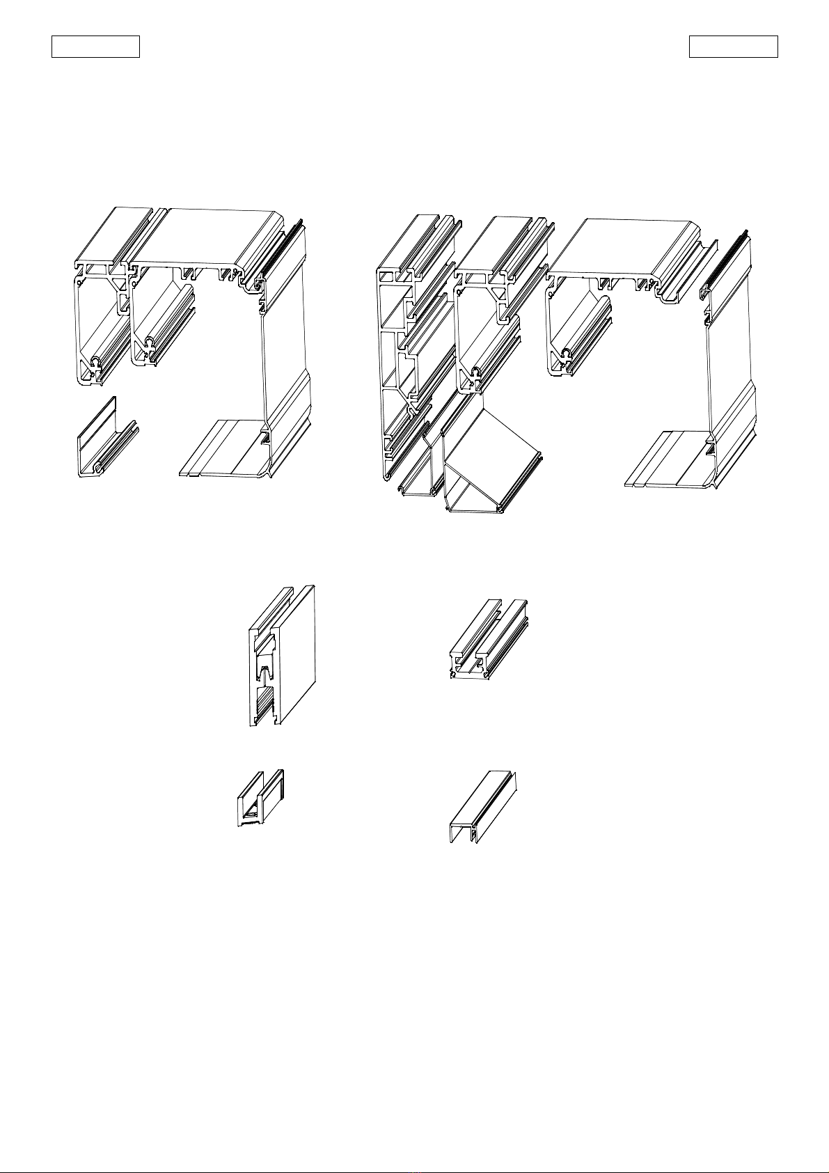
Closing profile (fig. 2 ref. )
Available in natural and anodised aluminium versions, the profile is
used for closing the space between the mobile leaf and the wall on
which the head profile is secured.
Closing profile for free-standing facility (fig.3 ref. )
Available in anodised aluminium versions, the profile is used for
closing the space between the mobile leaf and the wall on which
the head profile is secured.
Brush for closing profiles (fig. 2 ref. and fig. 3 ref. )
Prevents dust reaching inside the head profile.
Pair of sliding blocks (fig.14 ref.)
Supplied as a pair, they can be secured to the wall (or on the
stationary leaf) or directly on the floor.
Bottom track profile (fig. 14 ref. )
Allows the bottom leaf profile to adapt to the sliding block
mentionedabove.
Brushforbottom track profile (fig. 14 ref. )
This completes the on-ground track system.
Leafattachmentprofile(fig. 17ref.)
Allows the top leaf profile to adapt to the carriage attachments.
Pair of bottom sliding blocks for glass leaf
They enable the glass leaves to slide.
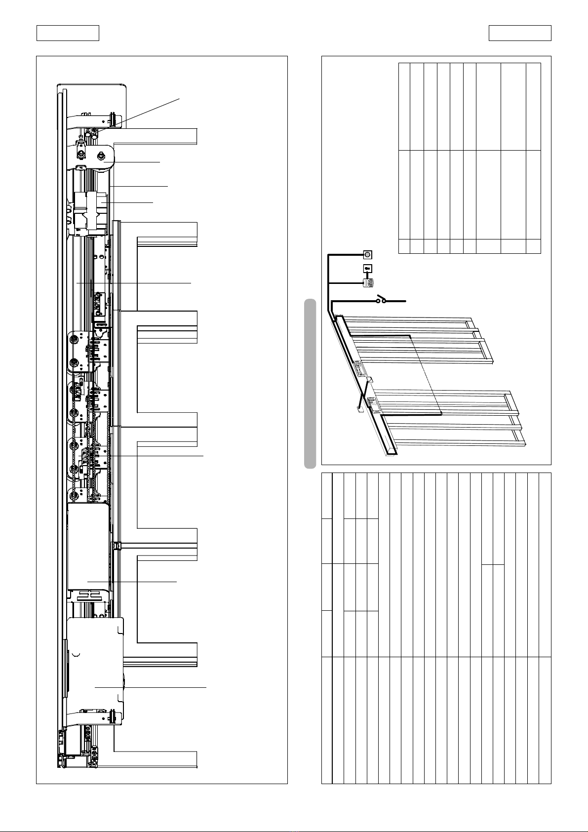
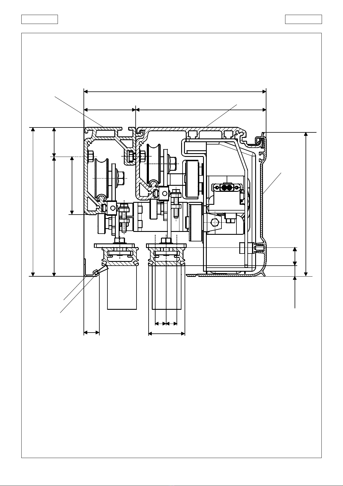
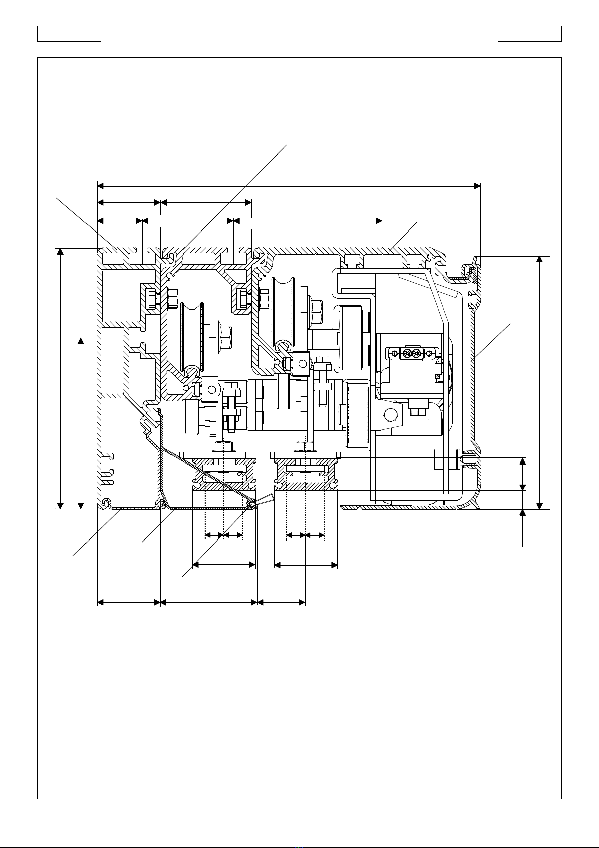
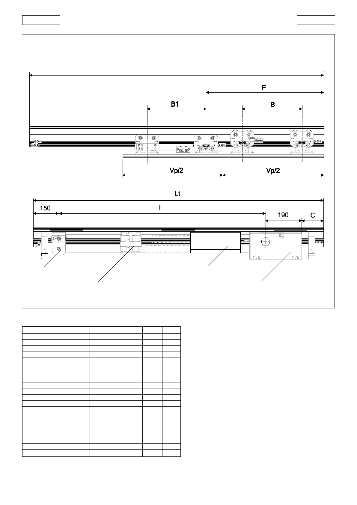
4. HEAD PROFILE CONFIGURATION
To correctly position the head profile parts, refer to the dimensions of
thefollowingfigures:
Fig. 4 right opening, Fig. 5 left opening and Fig. 6 double-leaf.
With the FAAC series 940 SMT systems, two- or four-leaf sliding doors
can be automatically activated, managed and controlled.
The FAAC series 940 SMT automated systems are supplied fully
assembled, wired and tested in the configuration requested by the
customer on the order form, or supplied as a kit.
An automation head profile (fig.1 ) consists of the following parts:
Headprofile (fig.1ref. )
The profiles in extruded aluminium, used for the different head profile
models(tab.1) comein twoversions:
Profile SM (fig.2 and 3 ref. )
This is the support profile which is used when the head profile can be
entirely fitted on a bearing structure. The profile's sliding track is
coated with a special plastic material which, in addition to
protectingthe aluminium profileagainst wear, ensuressilent
operationwith avery low frictioncoefficient.
Telescopic profile (fig.2 and 3 ref. )
This is the support profile for the telescopic leaves.
Profile SMA (fig.3 ref. )
This consists of a support profile (SM) and another profile (A)
providingthefree-standingcharacteristic.
The head profile can be secured at the two ends, using the "Side
fixingbracketskit".
The free-standing profile secured at the ends is guaranteed up to a
maximum length of 3,000 mm - for greater lengths, the head profile
must be secured at its intermediate points too, using the
appropriateslots.
Leafsupportcarriages (fig.1ref.)
The carriages are provided with two wheels on ball bearings, a
counter wheel on the lower part, and a screw system for adjusting
leafheight.
Motor/transformer unit (fig. 1 ref.)
The DC motor is supplied with an encoder and a leaf locking system
(accessory).
Control unit (fig. 1 ref. )
When the microprocessor control unit is powered up, it executes an
initialisationprocessof thedoor's functionalparameters.
Opening mechanical stop (fig. 1 ref. )
Transmission pulley unit (fig. 1 ref. )
Drive chain (fig. 1 ref. )
3. ACCESSORIES
FAAC has three groups of articles complementing the installation of
the automatic door.
3.1 Supplied accessories for the head profile
These are the articles which, following a request on the order form,
are assembled on the head profile directly by FAAC. These
accessories, which can be, if necessary, installed later on, are as
follows:
Front housing (fig.2 ref. and fig. 3 ref. )
The front housing is available in natural or anodised aluminium.The
side panels fully enclose the system.
Motor lock unit
The motor lock unit guarantees mechanical locking of the door in
any position. A single type of motor lock is used for either single- or
double-leafapplications.
The motor lock is supplied with an internal release device enabling
emergencyopening if necessary; itis also designed forinstallation of
the external release (paragraph 3.2 key push-buttons T20EF and
940SMT2/SMT4 SERIES AUTOMATIC DOORS
2. DESCRIPTION AND TECHNICAL SPECIFICATIONS