DEUTSCHTEC PRIMEDRIVE User manual

Installation manual
Deutschtec GmbH
Am Fuchsbau 13
15345 Petershagen/
Eggersdorf Deutschland
Phone: +49 (0)3341 30 22 4 - 0
Fax: +49 (0)3341 30 22 4 - 25
www.deutschtec.de
PRIMEDRIVE

Contents
1EN.22.04032019
4.1
Check leaves and opening dimentions
9
4.3 Use laser level to specify second point-corridor mounting 10
4.2 Install bracket on both side walls - corridor mounting 10
9
Installation steps
4.
Safety Instructions
1. 3
Initial Assembly
1.1 3
Maintenance
1.2 3
Explanation of Symbols
1.4 3
Operation
1.3 3
Contents of Delivery
2. 5
Commencing Assembly
3.
8
Technical Data
3.1 8
Required Tools
3.2 8
Hang on back profile on bracket-corridor mounting 11
4.4
4.5 Fix back profile-corridor mounting 12
4.7 Fix the rail - on facade 13
4.6 Adjust rail horizontally - on facade 12
Insert nuts and screws in rail groove 13
4.8
4.9 Install rail profile and track profile 14
4.11 Install hangers through the rail 15
4.10 Install stoppers 15
Fix the counter rollers and mind the 0.5 mm gap 16
4.12
4.13 Install components 17
4.15 Check components‘ layout 19
4.14 Install lock (optional) 18
Hang on the rail on back profile-corridor mounting 20
4.16
4.17
Fix the rail-corridor mounting 20
4.19 Install filler for each fixed leaf-corridor mounting 21
4.18 Install notch on side walls-corridor mounting 21
Install joiner plate on each fixed leaf-corridor mounting 22
4.20
4.21 Slide side leaves 22
4.23 Turn the screw until it touches the back profile-corridor mounting 23
4.22 Fix side leaves-corridor mounting 23
Drill a hole for sensor through the rail and back profile 24
4.24
4.25 Cleaning 24
4.27 Hang on moveable leaves 25
4.26 Install floor guides 25
Adjust leaves‘ clearance 26
4.28
Declaration of Incorporation
1.5 4

2EN.22.04032019
4.30 Close moveable leaves and adjust lock in correct position 27
4.29 Adjust moveable leaves‘ height clearance 26
Install the timing belt 27
4.31
4.32 Adjust belt tension 28
4.34 Install emergency button 29
4.33 Install mechanical key switch 28
35
Wiring Diagrams
8.
Install outside sensor
4.36 30
Install operator cover
4.37 30
Install inside sensor
4.38 32
Starting up the Operator
5. 32
Modifying the Parameters
6.
33
Wiring Diagram Optex OA-Flex Sensor
8.1 35
Wiring Diagram BEA ZEN/ZENSAFE Sensor
8.2 36
Wiring Diagram BEA IXIO-DT3 Sensor
8.3 37
Mechanical Key Switch
10.
39
40
11.
Troubleshooting
12. 41
LED Status - Error Codes
Wiring Diagram BEA VIO Sensor
8.4 38
Block Diagram
9. 39
Sensors’ Setup Table
7.
34
Install wall flush mounting 29
4.35

3
1. Safety Instructions
We recommend that you follow the instructions described below in
order to avoid material damage and personal injuries. All of the
instructions that need to be followed with a special degree of diligence
have been marked with a symbol. If you have any questions, we
recommend that you contact your supplier. Although we have exercised
a great degree of diligence in creating these instructions, they do not
absolve you of your own responsibility. All the tasks should be carried
out by professionals or by trained personnel. Deviations can result in
faulty functioning and voiding the warranty. Use protective equipment,
gloves and goggles.
1.1 Initial Assembly
Secure your installation site against unlawful entry by unauthorized individuals. Ensure that the location in
question is well-lit and that the floor is secure. Use appropriate measures to protect the site from
contaminants. Check the stability of the structure. Work on electrical systems must be performed by
authorized staff. Deutschtec GmbH shall not be liable for accidents caused by improper assembly,
maintenance and operation.
1.2 Maintenance
Before work, examine the status of the door, particularly the safety elements, and the general condition.
Damage to the glass, the electrical feed and the mechanical function (e.g. stiffness and wedging) must
be repaired prior to maintenance. Secure your installation site against unlawful entry by unauthorized
individuals.
1.3 Operation
Check the operational status of the door on a daily basis. In case of operational irregularities,
decommission the door and notify your service partner. When the system is locked, the escape function
is disabled!
1.4 Explanation of Symbols
Warning: Risk of Injury
Wa r n i n g: Electri c Shock P o s s i ble
(risk of injury or death) Repairs should be
carried out by an electrician.
EN.22.04032019

EN.22.04032019
1.5 Decleration of Incorporation
Sliding Door Operator Type:
Serial Number:
Year of Manufacture:
17.01.2017
4

5
Art.-No. Description
1000000057 PR Control Unit - Steel Case
1000000640 PR240 Assembled Motor100 W-24V
1000000799 PR239 Assembled Motor 50 W-24V
1000000076 PR Power Pack Steel Case
This kit/set incl.
2 Pcs.
PrimeDrive/FR
PrimeDrive240
PrimeDrive239
1 Pcs.
PrimeDrive/FR
PrimeDrive240
1 Pcs. PrimeDrive239
1 Pcs. PrimeDrive/FR
PrimeDrive240
PrimeDrive239
1000000641 Prime Assembled Idler Pulley
1000000978 Prime Stopper Set
1 Pcs. PrimeDrive240
PrimeDrive239
1 Pack. PrimeDrive/FR
PrimeDrive240
PrimeDrive239
1000000966 Prime Belt Clamp Set PrimeDrive/FR
PrimeDrive240
PrimeDrive239
1000000646 Prime Hanger & Roller 36mm 4 Pcs. PrimeDrive/FR
PrimeDrive240
PrimeDrive239
1000000987 Prime Side Cover PrimeDrive/FR
PrimeDrive240
PrimeDrive239
1000000981 Prime Cover Clip Set PrimeDrive/FR
PrimeDrive240
PrimeDrive239
1 Pack.
1 Pack.
1 Pack.
1 Pcs.
1 Pcs.
1 Pcs.
1 Pcs.
1 Pcs.
1 Pack.
1 Pack.
1 Pack.
1 Pack.
4 Pcs.
4 Pcs.
1 Pack.
1 Pack.
1 Pack.
1 Pack.
2 Pcs.
2. Contents of Delivery- PrimeDrive Operator Kit
EN.22.04032019

EN.22.04032019
6
Art.-No. Description
1000000532 Prime Screw Pack
1000000119 Prime Standard Cable Pack
1000000116 GN Cable Clip
1000000124 Battery pack - GN
This kit/set incl.
1 Set
PrimeDrive/FR
PrimeDrive240
PrimeDrive239
PrimeDrive/FR
PrimeDrive/FR
PrimeDrive240
PrimeDrive239
PrimeDrive240
PrimeDrive239
2 Pack.
1 Pack.
1 Pack.
1 Pack.
1 Pack.
1 Set
1 Pack.
1 Pack.
Prime FRW Cable Pack
PrimeDrive/FR
1 Set
1000001810
PrimeDrive Standard Profile Set
Art.-No. Description
1000000934 4m Prime Cover profile , AL
1000000933 4m Prime Rail Profile , AL
1000000004 4m General Track Profile, AL
This kit/set incl.
1 Pcs. Stainless steel set
Aluminium set
1 Pcs.
1 Pcs. Aluminium set
Stainless steel set
Aluminium set
1000000005 General Rubber Profile, for AL Aluminium set
1 Pcs.

1000000975 4m PrimeDrive-Back Profile 1 Pcs. optional
1000000024 General Rubber Profile, for SS Stainless steel set
1000000023 4m General Track Profile, SS 1 Pcs. Stainless steel set
1 Pcs.
7
Art.-No. Description
1000000147 Mechanical Key Switch (Deutschtec logo)
1000000166 Digital Programme Switch (Deutschtec logo)
1000000174
Accessories
optional
optional
optional
1000000124 Battery Pack - GN optional
1000000392 Battery Set - GN optional
1000000980 HSML_Complete Lock for Prime optional
1000000198 Frameless Glass Clamp Set - IR optional
1000000195 Timing Belt HTD 8M, 12mm, 4.5 meter * optional
Electromechanical Lock-GN
PrimeDrive240
PrimeDrive239
PrimeDrive240
PrimeDrive239
* Other lengths are available.
MADE IN GERMANY
EN.22.04032019

EN.22.04032019
8
3. Commencing assembly
3.1 Technical Data
Power Supply:
Frequency:
Power Consumption:
Power Consumption in Idle State:
Protection Class:
Type of Protection:
Temperature Range:
Max. Weight of Leaf:
Passage Width:
Max. Passage Height:
Opening Speeds:
Closing Speeds:
Hold-open Time:
Sound Emission:
230 V AC
50 Hz
max. 160 W
5 W
1
IP20
-15 to +50°C
PrimeDrive239: 2 x 100 Kg
800 - 3000 mm
3000 mm
100-550 mm/s
100-500 mm/s
1-30 s
< 70 dBA
Max. Weight of Leaf: PrimeDrive240: 2 x 150 Kg
3.2 Required Tools
Ring spanner
10 & 13 mm
Monkey
wrench
Side cutters
Drill (+ masonry drill)
6, 8 und 10 mm
Cordless
screwdriver
+ bit set
Water level
Tape measure
Combination
pliers
Screwdrivers in ( - / +)
various sizes
Ladder
Drive screw
borer
Socket wrench
4 & 5 & 6
Metal drill
6 & 8 mm

9
4. Installation Steps
4.1 Check leaves & opening dimensions:
Note : This installation manual is based on combination of PrimeDrive-series ‘ operator
with back profile and THB frame.
EN.22.04032019

EN.22.04032019
10
4.3 Use laser level to specify second point - corridor mounting:
4.2 Install bracket on both side walls - corridor mounting:
*Installation material based on requirement
Laser level

11
4.4 Hang on the back profile on bracket - corridor mounting:
EN.22.04032019

EN.22.04032019
12
4.5 Fix the back profile - corridor mounting:
4.6 Adjust the rail horizontally – on facade:
13
4.7 Fix the rail – on facade:
4.8 Insert nuts & screws in rail groove:
EN.22.04032019

EN.22.04032019
14
PrimeDrive/FR:
4.9 Install rail profile and track profile:

15
4.10 Install stoppers:
4.11 Install hangers through the rail:
EN.22.04032019

16
4.12 Fix the counter rollers and mind the 0.5mm gap:
EN.22.04032019

17
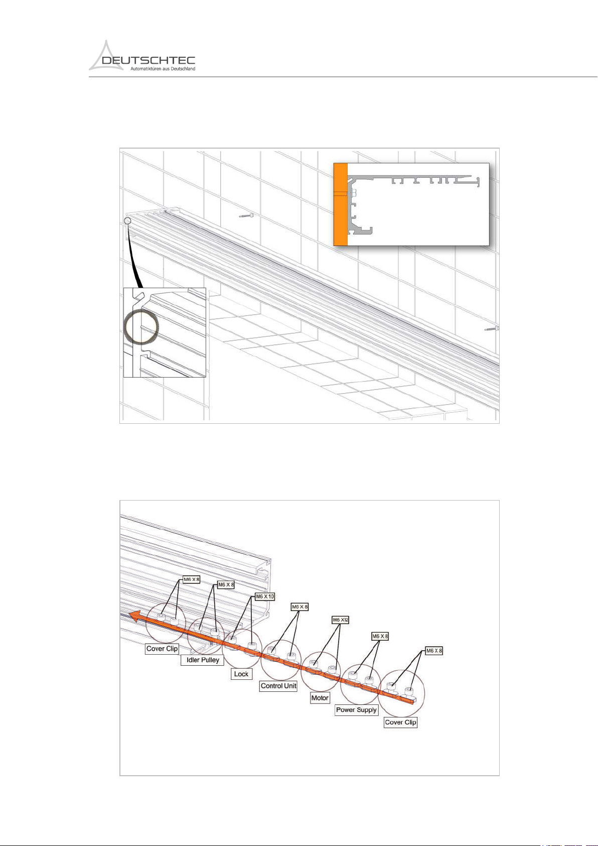
4.13 Install components:
EN.22.04032019

18
PrimeDrive/FR:
4.14 Install lock (optional):
EN.22.04032019

19
Idler
Battery
Lock
Control Unit Power Supply
Motor
4.15 Check components‘ layout:
PrimeDrive/FR:
Motor
Lock
Motor
Battery Power Supply
Control Unit
Control Unit
EN.22.04032019
Table of contents
Other DEUTSCHTEC Door Opening System manuals


Popular Door Opening System manuals by other brands


PDQ
PDQ 6EWS STS Installation instruction

RADEMACHER
RADEMACHER RolloPort S2 Translation of the Original Operating and Assembly Manual

DITEC
DITEC DAS107PLUS user manual

Assa Abloy
Assa Abloy Corbin Russwin ED8200A Series installation instructions

CAMDEN
CAMDEN CM-550SK-V2 installation instructions

Assa Abloy
Assa Abloy Yale 1105 installation instructions

Assa Abloy
Assa Abloy SARGENT 8800 Series Instructions for installing

Overhead door
Overhead door RMX DRAWBAR manual

Dorma
Dorma RTS Series quick start guide

WITTUR
WITTUR Hydra PLUS manual

TOPP
TOPP S200 Instructions for installation and use

Hafele
Hafele 940.41.043 Installation instructions operating instructions