Important
Note
·The
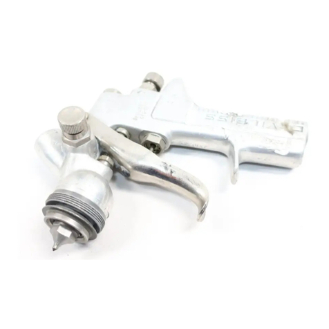
SGA570
spny
~JUn
rs
a precisron tool, desrgned and
manufactured
to
render
high qualrty
trr.istl€<>
·In
order
to marntarn
rts
pertormance
characterrsrrcs it
rs
important
that
you
carefully
follow the mstructrons here:n
Application
WARNING'
CHLORINATED
SOLVENTES
SUCH
AS
111-TRJCHLOROETHANE
AND
METHYLENE
IN THIS
CHEMICALLY
REACT
WITH
THE
ALUMINUM
USED
IN
THIS
GUN.
THE
RESULT
OF
THIS
REACTION
CAN
RANGE
FROM
DESTRUCTIVE
CORROSION
TO
A
HAZARDOUS
EXPLOSION.
00
NOT
USE
THESE
SOLVENTS
WITH
THIS
SPRAY
GUN.
•The
SGA
spray
gun
was
developed
fo~
use
in
automobile
reparr
sr-.ops
and
general
maintenance
work
·It
rs
adequate
fm applyrng all
common
coating and frnishing materials,
excepting
ccmosrve.
abrasive
products anzi
those
With
very
high
viscosity.
How
it
Works
• The
SGA-570
DeVilbiSS
spray
gun
works
through suction it
draws
the
material
from the cup through a
suction
tube
• The pattern
1s
adjusted
by
the
top
knob
•
Flwd
flow
IS
adjusted
by
the
lower
one
Installation
For
better
performance
of
the
DeVilbiss
SGA-570
we
recommend
that
• The
DeVilbiss
air filter
regulator
be installed as close as
possible
to
the
spray
gun
•
The
mternal
diameter
of
the
DeVi/t)iss air
hose
should
not
be
less
than
5116", for a
maximum
length
of
50
feet (15 meters)
Operation
fhe
air
valve
assembly
(6)
is
under
pressure
whenever
the
gun
ts tnggered. If this
valve
is
turned
out
too far, it
may
!eave the
gun
forcefully
when
rhe
gun
is
triggered
Also,
the
"0"
ring (5)
may
be
dammaged
rf
the valve
is
turned
out
past
the
first
thread
[)o
not
turn the valve past
the
first thread
-there
will be no
effect
on
the
spray
pattern
after
that
positton.
•
Prepare
the
mate
nat
wt>ich is to be
sprayed
according
to
the
manufacturer's
n:structions and filter it
ttlrough
a
sueeen
of
at
least
60
mesh,
or
equivalent.
• Set
the
atr pressure
at
the
DeVilbiss
filter
regulator
to
about
35
p.s.i. to start.
•
Effect
a
spray
test
•
Spray
a test pattern.
Regulate
the fan by opemng
or
closing its
adjusting
knob
•
Spray
a
small
area
in
order
to
achieve
the
desired
job
speed
and
finish.
•
If
the ftnish
appears
to be
dry
or
rough, the
quanttty
of
material
is
small
in relation to
the air
pressure
Open the fluid regulating knob,
or
decrease
the air
presure
in
the
DeVilbiss
filter
regulator
until
you
achieve
a
wet
and full coattng.
•
Keep
the
spray
gun
always
perpendicular
to the surface
which
is to
be
painted
·Do
not
arc
the
gun
as thts
produces
an
uneven
coat
of
paint
·We
recommend
the spray
gun
be
kept
at
a
distance
of
6 to 8 inches from
the
''urface
• The positton
of
the air cap
determines
the
position
of
the
pattern
Twist
the
cap
;Jccording to
spraying
requenments
Cleaning
We
recommend
that the
spray
gun
be
cleaned daily,
or
after
each
time
the
equipment
is
used
Procedure
•
Remove
the
cup
Empty
the
remaining
matenal
from
the
cup
and
refill it with
about
c:ne
inch
of
suitable solvent.
•
Put
cup
back
on
gun
and
shake
same
• Pull
the
trigger
for
a while
•
loosen
the
cup
again and
clean
1!
Inside
w1th
a cloth
using
the
remaining
solvent.
Clean
also
the
lid and
suction
tube
•
Repeat
the flushing
procedure
at
least
once
aga1n.
•
W1pe
the
extenor
of
the
gun
with
a
solvent
dampened
cloth
•
If
necessary
,
remove
tne
air
cap
and
clean
1t
by
1mmers1ng
same
in
solvent
If
the
holes
have
clogged
use
a
toothpick
to
remove
the obstruction_
Never
use
wires
or
nails, as this could ruin the air
cap
•
Never
immerse
the
spray
gun
m
solvent
since
this
destroys
the
lubricants
and
packmgs
Lubrication
·Lubricate
.daily
w1th
thin oil
the
tngger
bear1ng stud (17), the fluid
needle
(10),
close
to the
packtng
(14),
the
threads
of
the
valve
assembly
(6) and
the
exposed
part
of
the
wr
valve
(8)
•
Periodically
cover
the
springs
of
the
needle
(1
1)
and
of
the
air
valve
(9) with
vaseline
or
thm grease
When
to
change
the
tip
and needle
The tip
and
netedle should he replau::d
when
·There
occurs
wea1
of
the
11p,
ol
the
needle
or
th'~
sent
d the t!p
• There are
SIQrls
of
wear
on
the needle
at
the pornt
of
contact
W!th
1t1e
packmg
•
NE'·ver
replace on!y
th('
fluid tip (3)
or
the need!e (10)
Al>w1ys
chanQe both
of
t~em
·The
t1p
should
be
screwed
on
carefully
1n
order
not to
hurt
tile
(hre:vJ
of
the
gun
body.
Thtghten
1!
tor a good sealing. but
never
over-ltghten
it Always
use
ttle
DeV1Ibiss
BSGA-29
wrench
Always
ttghten the fluid ttp before assernlJhng the
neediH rnto the
gun
body
• The t:p
should
be
screwed
on
carefully
1rl
order
not
to
hurt
the
thread
of
th•:
gun
body
Tighten
1\
lor a
good
sealmg. but
new:r
ove~-trghlH\
rt
Always
t/>e tr;e
DeVilbiss
BSGA-29
wrench_
Always
t1ghtr::m
the
Hu:d
tip with a
torque
of
15
to
17
Ft Lbs.
before
assembling
the
needle into
the
gun
body
• Always
replace
the packrng (14)
whHl
you assernbie a
new
set of
t1p
and
needle
Lubrtcate the
new
p8.cking oefore asse-mbly
·The
packing
nut
(15)
should
be
just
t1ght
enough
and
not
hmder
the free
movement
of the
needle
REPAIR KITS
K-5001
K-5004
~-
··r
QTY
: DeV.
DESCRIP_!"!_?.N.
QTY.
DeV. DESCRIPTION
'
~-~~-~
j
BSGA-32
F!Uid
tip
j
BSGB-15
Packtng
j I
BSGA-404
Fluid
needle
3
BSS-601011
"0"
Ring
2
'BSGS-15
Packmg
BSS-601109
"O"
R1ng
BSGB·5
Baffle 1
BSGA-49
Sprmg
I j
CGA-40
Spring
i j
BSGA-16
Tngger
pin
2
SST-8416
Snap
nng
HOW TO REQUEST REPLACEMENT PARTS
When
requestmg
replacement
parts always
g1ve
the ·1. Kit
or
Part
Code-2
Description
of
same
-3 Type
ol
spray
gun
SERVICE CHECKS
'
'
) (
•
:
Condition
Top/or
bottom
heavy
pattern
Heavy
right
or
left
s1de
pattern
Heavy
center
pattern
Spilt
spray
pattern.
Jerky
or
fluttering
spray
Cause
1
Matenal
build
up
on
atr cap
2 Partially
plugged
horn
holes,
center
hole or
jets
'3.
Matenal
partially
i
plugged
flwd
tip
!4
Dammaged
fluid tip.
1.
Too
much
material
2 Material
too
thick
I'
Pressure
is
too
high
2.
Not
enough
material
1 InsuffiCient flwd
in
cup.
2
Gun
and
cup
tipped
at
excessive
angle
3 OtstniCted
fluid
passage
4
loose
or
cracked
fluid tube in
cup
i 5.
loose
fluid
tip
or
I cracked fluid tip
seat
6. Too
heavy
fluid for
suction feed
i
7.
Dry
or
worn
packing
I (14)
or
loose
packing
nut
(15)
________
i
Will
not
spray
1
1
Low
air
pressure
1
at
gun
l2
Closed
fluid
adjusting
! knob
1
3
Too
.heavy fluid
tor
suctton feed
, 4
loose
a1r
cap
I
Correction
--r-
'1.
Remove
cap and
soak
it
in
suitable sotvent
and
wipe
clean (See Cleaning)
2
Same
as
above
3.
Remove
ffuid
tip
and
clean same with soivent.
4.
Replace
t1p
and
needle
set
(See
When
toChan_;je
~~.Pard
Need~)
1
Reduce
flUid
flow
by
turning needle adjusting
knob clockwise or increase
air
pressure
in
th'2
DeVilbls.s
filter regulator.
2
Thin
matenal
1.
Reduce
a11
pressure
of
the DeVilb1ss filter
regulator.
2.
Ir.crease fluid flow
by
turning fluid
needle
adjusting
knob
counterclockwise
1
F1ll
cup
2
Do
not
tip
excessively
or rotate fluid
tubE:>
in
cup.
3.
Clean
same
4
Tighten
or
rep!ace
same
5 T1ghten
or
replace
the
lip
and needle
set
6 Thtn
matenal
7.
lubncate
or
replace
packing
or tighten
packing
nut
Ched< air lines or 1mease
pressure
at
OeVrlbiss
air
filter regulator.
2.
Open
same
..
(See
Operal!On)
j 3
Thin
material
4 Tighten
same
Dripping
from
_____
ft~,uid
tip.
--[1.-
Worn
or
damaged
-;rp
_i~~.
need
I~-
---·-
....
-
..
Replace
ttp
and
needle
set
(See
When
to
C~an_g_e
Tip
an_d_
Needle)-~
~
DEVILBISS
~
RAMSBURG
DeVilbiss
Ransburg
Industrial
Coating
Equipment
17241ndian
Wood
Circle
INDUSTRIAL
COATING
EQUIPMENT
Mawmee,
OH
43537
SB2A95C
06/91
