Devolo Giga Bridge User manual

Manual
devolo Giga Bridge

devolo Giga Bridge

© 2021 devolo AG Aachen (Germany)
The reproduction and distribution of the documentation and software supplied with this product and the use of its contents is
subject to written authorization from devolo. We reserve the right to make any alterations that arise as the result of technical de-
velopment.
Trademarks
devolo and the devolo logo are registered trademarks of devolo AG.
The firmware package from devolo contains files which are covered by different licenses, in particular under devolo proprietary
license and under open source license (GNU General Public License, GNU Lesser General Public License or FreeBSD License). The
source code which is available for Open Source distribution can be requested in writing from [email protected].
All other names mentioned may be trademarks or registered trademarks of their respective owners. Subject to change without
notice. No liability for technical errors or omissions.
devolo AG
Charlottenburger Allee 67
52068 Aachen
Germany
www.devolo.global
Version 1.0_5/21

devolo Giga Bridge
Contents
1 Preface . . . . . . . . . . . . . . . . . . . . . . . . . . . . . . . . . . . . . . . . . . . . . . . . . . . . . . . . . . . . . . . . . . . . . . . . . . . . . . . . . . . . . 6
1.1 About this manual . . . . . . . . . . . . . . . . . . . . . . . . . . . . . . . . . . . . . . . . . . . . . . . . . . . . . . . . . . . . . . . . . . . . . 6
1.2 Intended use . . . . . . . . . . . . . . . . . . . . . . . . . . . . . . . . . . . . . . . . . . . . . . . . . . . . . . . . . . . . . . . . . . . . . . . . . . 8
1.3 CE conformity . . . . . . . . . . . . . . . . . . . . . . . . . . . . . . . . . . . . . . . . . . . . . . . . . . . . . . . . . . . . . . . . . . . . . . . . . 9
1.4 Safety notes . . . . . . . . . . . . . . . . . . . . . . . . . . . . . . . . . . . . . . . . . . . . . . . . . . . . . . . . . . . . . . . . . . . . . . . . . . . 9
1.5 devolo on the Internet . . . . . . . . . . . . . . . . . . . . . . . . . . . . . . . . . . . . . . . . . . . . . . . . . . . . . . . . . . . . . . . . 10
2 Introduction . . . . . . . . . . . . . . . . . . . . . . . . . . . . . . . . . . . . . . . . . . . . . . . . . . . . . . . . . . . . . . . . . . . . . . . . . . . . . . . 11
2.1 Connection problems . . . . . . . . . . . . . . . . . . . . . . . . . . . . . . . . . . . . . . . . . . . . . . . . . . . . . . . . . . . . . . . . . 11
2.2 The solution: devolo Giga Bridge . . . . . . . . . . . . . . . . . . . . . . . . . . . . . . . . . . . . . . . . . . . . . . . . . . . . . . 12
2.3 Possible applications of the devolo Giga Bridge . . . . . . . . . . . . . . . . . . . . . . . . . . . . . . . . . . . . . . . . . 12
2.4 Introducing the devolo Giga Bridge . . . . . . . . . . . . . . . . . . . . . . . . . . . . . . . . . . . . . . . . . . . . . . . . . . . . 16
2.4.1 Reading the indicator light . . . . . . . . . . . . . . . . . . . . . . . . . . . . . . . . . . . . . . . . . . . . . . . . . . . . . 18
2.4.2 Connections . . . . . . . . . . . . . . . . . . . . . . . . . . . . . . . . . . . . . . . . . . . . . . . . . . . . . . . . . . . . . . . . . . 21
2.4.3 Integrated electrical socket . . . . . . . . . . . . . . . . . . . . . . . . . . . . . . . . . . . . . . . . . . . . . . . . . . . . 21
3 Initial use . . . . . . . . . . . . . . . . . . . . . . . . . . . . . . . . . . . . . . . . . . . . . . . . . . . . . . . . . . . . . . . . . . . . . . . . . . . . . . . . . . 22
3.1 Package contents . . . . . . . . . . . . . . . . . . . . . . . . . . . . . . . . . . . . . . . . . . . . . . . . . . . . . . . . . . . . . . . . . . . . . 22
3.2 Connecting the devolo Giga Bridge . . . . . . . . . . . . . . . . . . . . . . . . . . . . . . . . . . . . . . . . . . . . . . . . . . . . 22
3.3 Pairing – Establishing a G.hn connection . . . . . . . . . . . . . . . . . . . . . . . . . . . . . . . . . . . . . . . . . . . . . . . 23
3.3.1 Manual triggering the pairing of a devolo Giga Bridge adapter . . . . . . . . . . . . . . . . . . . 25
3.4 Connecting the NT/ONT and devolo Giga Bridge . . . . . . . . . . . . . . . . . . . . . . . . . . . . . . . . . . . . . . . 25
3.4.1 Wiring the devolo Giga Bridge to the router . . . . . . . . . . . . . . . . . . . . . . . . . . . . . . . . . . . . 27
3.4.2 Expanding your in-home LAN coverage . . . . . . . . . . . . . . . . . . . . . . . . . . . . . . . . . . . . . . . . . 30
4 Configuration . . . . . . . . . . . . . . . . . . . . . . . . . . . . . . . . . . . . . . . . . . . . . . . . . . . . . . . . . . . . . . . . . . . . . . . . . . . . . 31
4.1 Calling up the built-in web interface . . . . . . . . . . . . . . . . . . . . . . . . . . . . . . . . . . . . . . . . . . . . . . . . . . . 31
4.2 Menu description . . . . . . . . . . . . . . . . . . . . . . . . . . . . . . . . . . . . . . . . . . . . . . . . . . . . . . . . . . . . . . . . . . . . . 32
4.3 Overview . . . . . . . . . . . . . . . . . . . . . . . . . . . . . . . . . . . . . . . . . . . . . . . . . . . . . . . . . . . . . . . . . . . . . . . . . . . . 35
4.3.1 G.hn . . . . . . . . . . . . . . . . . . . . . . . . . . . . . . . . . . . . . . . . . . . . . . . . . . . . . . . . . . . . . . . . . . . . . . . . . . 37
4.3.2 LAN . . . . . . . . . . . . . . . . . . . . . . . . . . . . . . . . . . . . . . . . . . . . . . . . . . . . . . . . . . . . . . . . . . . . . . . . . . 40

devolo Giga Bridge
4.3.3 System . . . . . . . . . . . . . . . . . . . . . . . . . . . . . . . . . . . . . . . . . . . . . . . . . . . . . . . . . . . . . . . . . . . . . . . 41
4.3.4 Configuration . . . . . . . . . . . . . . . . . . . . . . . . . . . . . . . . . . . . . . . . . . . . . . . . . . . . . . . . . . . . . . . . . 44
4.3.5 Wizard . . . . . . . . . . . . . . . . . . . . . . . . . . . . . . . . . . . . . . . . . . . . . . . . . . . . . . . . . . . . . . . . . . . . . . . 45
4.3.6 Firmware . . . . . . . . . . . . . . . . . . . . . . . . . . . . . . . . . . . . . . . . . . . . . . . . . . . . . . . . . . . . . . . . . . . . . 45
5 Appendix . . . . . . . . . . . . . . . . . . . . . . . . . . . . . . . . . . . . . . . . . . . . . . . . . . . . . . . . . . . . . . . . . . . . . . . . . . . . . . . . . . 47
5.1 Technical data . . . . . . . . . . . . . . . . . . . . . . . . . . . . . . . . . . . . . . . . . . . . . . . . . . . . . . . . . . . . . . . . . . . . . . . . 47
5.2 Disposal of old devices . . . . . . . . . . . . . . . . . . . . . . . . . . . . . . . . . . . . . . . . . . . . . . . . . . . . . . . . . . . . . . . . 47
5.3 Warranty conditions . . . . . . . . . . . . . . . . . . . . . . . . . . . . . . . . . . . . . . . . . . . . . . . . . . . . . . . . . . . . . . . . . . 48

Preface 6
devolo Giga Bridge
1Preface
Get fibre-optic Internet into your home living
room using a coaxial or telephone line!
The devolo Giga Bridge gives you a fibre-optic In-
ternet connection quickly and without any incon-
venient routing of new network cables to your
living room. Bridge the distance from the active or
passive NT (Network Termination)/ONT (Optical
Network Termination) to the router quickly and
easily using an existing coaxial (SAT/TV) or tele-
phone line that is no longer in use. The
devolo Giga Bridge uses this wiring to build a high-
speed point-to-point connection with a PHY rate
of up to 2 Gbps, allowing the full potential of the fi-
bre-optic connection to be used without the bur-
den of installing new cables. The PHY rate refers to
the speed of the physical layer. This is the maxi-
mum possible speed at which data can be trans-
mitted.
1.1 About this manual
Carefully read all instructions before setting up the
device and store the manual and/or installation
guide for later reference.
After the introduction of devolo Giga Bridge in
Chapter 2 and the different possible applications,
learn how you can successfully start up the
devolo Giga Bridge in Chapter 3. Chapter 4
describes the configuration of your
devolo Giga Bridge.
Tips and information about product safety and
environmental compatibility of the device, as well
as our warranty conditions, can be found in
Chapter 5 at the end of the manual.
Description of the icons
This section contains a brief description of the
icons used in this manual and/or on the rating
plate, the device connector, as well as the icons
used on the package:
Icon Description
Very important safety symbol that
warns you of hazardous electrical
voltage which if not avoided can re-
sult in serious injury or death.
Very important safety symbol that
warns you of a potentially danger-
ous situation which if not avoided
can result in serious injury or death.

7 Preface
devolo Giga Bridge
An important safety symbol that
warns you of a potentially burn
hazard which if not avoided can re-
sult in minor injuries or damage to
property.
An important safety symbol that
warns you of a potentially danger-
ous situation involving a tripping
hazard which can result in injuries.
An important note that should be
observed which can potentially
lead to material damages.
The device may only be used in-
doors in dry conditions.
The device is a Class I product. All
electrically conductive (made of
metal) housing parts where a volt-
age can be applied during opera-
tion or maintenance in the event of
an error must be continuously con-
nected to the earth wire.
Icon Description
The manufacturer/distributing
company uses the CE marking to
declare that the product meets all
applicable European regulations
and has been subjected to the pre-
scribed conformity assessment pro-
cedures.
It is used to prevent the occurrence
of waste electrical and electronic
equipment and to reduce this type
of waste through reuse, recycling
and other forms of utilisation. The
European Community WEEE Direc-
tive establishes minimum standards
for handling waste electrical and
electronic equipment in the EU.
Additional information,
background material and
configuration tips for your device.
Indicates a completed course of ac-
tion
Icon Description

Preface 8
devolo Giga Bridge
1.2 Intended use
Use devolo devices, devolo software and the pro-
vided accessories as described to prevent damage
and injury.
Products
devolo devices are communication devices de-
signed for indoors.* Depending on the product,
they are equipped with a PLC - (PowerLine Com-
munication) and/or a Wi-Fi module and/or a
broadband module. The devices communicate
with each other by means of, depending on the
product, PLC, data and telephone line (e.g. coaxial
or twisted pair) and/or Wi-Fi.
The devolo Giga Bridge is only intended to be used
on cleared—exclusively available—telephone or
coaxial cables. Free line availability without third-
party devices must be determined before connect-
ing the devolo Giga Bridge.
No liability is assumed for any damage to third-
party devices.
The devolo Giga Bridge is only suitable to be used
with telephone and coaxial lines inside buildings.
The use of telephone and coaxial lines outside of
buildings may negatively affect conformity and
cause the warranty claims to become void.
devolo devices do not replace the existing router.
They enable transmission of the existing Internet/
data signal over the in-house wiring and via Wi-Fi
and integrate Internet-compatible terminal devic-
es into the home network.
Under no circumstances may devolo devices be
used outdoors, because large temperature fluctua-
tions and moisture can damage both the device
and the power line*. devolo devices may not be in-
stalled at a height above two metres unless an ad-
ditional fastening mechanism is available. The
products are intended for operation in the EU,
Switzerland and Norway.
* This does not include devolo outdoor devices, which are suit-
able for outdoor applications based on their IP classification.
Software
devolo devices can be used only with the free,
downloadable programs approved and available
on devolo AG's website (www.devolo.global) and
in app stores (iOS and Google Play). Any modifica-
tions to the product-specific firmware or software
could damage the products and, in the worst-case
scenario, render them unusable, negatively affect
conformity and cause the warranty claims to be-
come void.
9 Preface
devolo Giga Bridge
Always use the most up-to-date software version
to make sure you have the latest security functions
and device updates. The installed devolo software
notifies you automatically if a new software ver-
sion is available.
Accessories
Use only the provided accessories.
1.3 CE conformity
The product corresponds to the basic re-
quirements of the Directives 2014/35/EU,
2014/30/EU, 2011/65/EU and 2009/
125/EC.
The product is intended for operation in the EU,
Switzerland and Norway.
A printout of a simplified CE declaration is included
with the product. You can also find it online at
www.devolo.global/support/ce.
1.4 Safety notes
It is essential to have read and understood all safe-
ty and operating instructions before the devolo de-
vice is used for the first time; keep them safe for
future reference.
DANGER! Electrical shock caused by elec-
tricity
Do not reach into the electrical socket.
Do not open the device.
Do not insert any objects into the electrical
socket or into the ventilation openings
DANGER! Electric shock caused by elec-
tricity
Device must be plugged into a power sock-
et with a connected earth wire
devolo devices may be operated only on a mains
power supply as described on the rating plate.
CAUTION! Tripping hazard
Lay the network cable in a barrier-free
manner;
ensure that the electrical socket and the
connected network devices are easily ac-
cessible
To disconnect devolo devices from the mains sup-
ply, unplug the device from the electrical socket.
CAUTION! Damage to the device caused
by ambient conditions
Only use device indoors in dry conditions

Preface 10
devolo Giga Bridge
CAUTION! Heat development during op-
eration
Certain housing components can become
very hot in certain situations. Attach device
so that it is touch-proof, observing optimal
positioning
devolo devices should only be installed at locations
that guarantee adequate ventilation. Slots and
openings on the housing are used for ventilation:
bDo not cover devolo devices during operation.
bDo not place any objects on devolo devices.
bDo not insert any objects into the openings of
devolo devices.
bdevolo devices must not be placed directly
next to a naked flame (such as fire or candles).
bdevolo devices must not be exposed to direct
heat radiation (e.g. radiator, direct sunlight).
Users do not need to carry out any maintenance
on devolo devices. In the event of damage, discon-
nect the devolo device from the mains supply by
pulling it or its plug out of the electrical socket.
Then contact qualified specialist personnel (after-
sales service) exclusively. Damage is deemed to
have occurred, for example,
bif a button is damaged.
bif the power plug is damaged.
bif the devolo device has been showered with
liquid (such as rain or other water).
bif the devolo device is inoperable.
bif the housing of the devolo device is damaged.
CAUTION! Damage to telephone, DSL
and/or TV services when connected to
non-cleared lines
Only use the device on cleared—exclusively
available—telephone or coaxial cables
CAUTION! Damage to housing from
cleaning agents containing solvents
Clean only electroless and with dry cloth
1.5 devolo on the Internet
For detailed information on our products, visit
www.devolo.global.
There you will find product descriptions and docu-
mentation, and also updates of devolo software
and your device's firmware.
If you have any further ideas or suggestions related
to our products, please don't hesitate to contact us

11 Introduction
devolo Giga Bridge
2 Introduction
2.1 Connection problems
For many fibre-optic providers, the connection
ends at the subscriber delivery point, which is the
termination point of the provider's Internet access.
This is often located in a basement, service en-
trance room or garage. From this point, the fibre-
optic connection is available for the NT/ONT.
Once the fibre-optic connection has been success-
fully connected to the subscriber delivery point,
the next step is to find the optimal place for the ac-
tive NT/ONT and router. Often the NT/ONT is
placed right next to the subscriber delivery point,
so the two devices can be easily connected to each
other. It is significantly more difficult to make the
following connection between the NT/ONT and
router, because it often requires recabling. After
all, the new high-speed Internet is supposed to
reach the terminal devices (e.g. smartphone, tab-
let, smart TV, laptop and game console) at full
speed. This is why most households have the rout-
er located in either the living room or a hallway.
Connecting the NT/ONT and router
The NT/ONT and router are connected exclusively
by network cables with an RJ45 connector; often
large distances need to be bridged for this pur-
pose. So, when providing cabling, customers have
to pay attention to the technical conditions of the
available network cables. Depending on the dis-
tance that needs to be covered from the NT/ONT
to the router or a corresponding terminal device,
there are a few pitfalls. Fixed network cables,
which lead to mains sockets, for example, are al-
lowed to have a maximum distance of 100 metres.
If the distance is expanded beyond that, it is not
compliant with Ethernet connection standards and
will lead to high attenuation of the cable as well as
latency (delay from the transmitter to receiver),
which has a significant effect on the data transmis-
sion and cancels out the advantage of gigabit In-
ternet. If it is still necessary to cover long distances
in the house, then customers have to use interme-
diate repeaters. Here, however, it must be ob-
served that, depending on the circuit, five to ten
metres have to be subtracted from the maximum
cable length. So having clean, optimal cabling for a
new fibre-optic connection is not exactly trivial and
requires good preparation.

Introduction 12
devolo Giga Bridge
2.2 The solution:
devolo Giga Bridge
The problems mentioned here mean additional ef-
fort and costs, but the devolo Giga Bridge provides
a solution. It uses the G.hn standard to bridge the
gap between the NT/ONT and router or terminal
device by using the home's existing coaxial line
(SAT/TV) or telephone line.
The devolo Giga Bridge can also be used to expand
the internal home network in order to connect de-
vices with an Ethernet port, e.g. computers, note-
books, televisions, game consoles, etc., to the
Internet.
This also achieves the best performance and stabil-
ity in places where network lines are not possible
or not wanted, and/or where Wi-Fi frequently
drops out due to ceilings and walls.
And the best part is that the devolo Giga Bridge is
connected easily by plug and play.
G.hn technology explained
The devolo Giga Bridge uses G.hn technology for
the transmission of the Internet signal over coaxial
(TV/SAT) or telephone lines. G.hn was developed
by the International Telecommunication Union
(ITU) with ongoing development provided primar-
ily by the HomeGrid Forum industry association.
2.3 Possible applications of the
devolo Giga Bridge
Difference between SISO and MIMO mode
bSISO: Single Input Single Output:
a Telephone line: Two telephone lines are
used here. The speed between the ONT and
router can reach up to 1 Gbps and the
range can be up to 100 metres.
a Coaxial line: Coaxial cables have very high
amount of insulation and high RF perfor-
mance (radio frequency). The speed
between the ONT and router can reach up
to 1 Gbps and the range can be several hun-
dreds of metres.
SISO mode is set to 200 MHz.

13 Introduction
devolo Giga Bridge
bMIMO: Multiple Input Multiple Output:
a Telephone line: Here, all four telephone
lines are used as pairs. The speed between
the router and another LAN device with an
Ethernet port can reach up to 1 Gbps and
the range can be more than 100 metres.
Expansion of the Ethernet WAN connection
using a telephone line
In this scenario, the G.hn signal is transmitted over
two or four telephone lines between the ONT and
router at a data rate of up to 1 Gbps. In the case of
two telephone lines, SISO mode is used. In MIMO
mode, all four lines are used as two pairs. MIMO
mode is recommended only for large distances ex-
ceeding 100 metres. For shorter distances, MIMO
transmission does not provide any higher data
rates.
Expansion of the Ethernet WAN connection
using a coaxial line
In this scenario, the G.hn signal is transmitted over
a standard coaxial cable between the ONT and the
router at a data rate of up to 1Gbps. Only SISO
mode can be used. Due to the high RF perfor-
mance of coaxial cables and the very high amount
of insulation, long distances of several hundred
metres can be bridged at data rates of up to 1 Gbps

Introduction 14
devolo Giga Bridge
Fig. 1 Expansion of the Ethernet WAN connection
using a telephone or coaxial line

15 Introduction
devolo Giga Bridge
Expansion of the internal home network using
a telephone line
In this scenario, the G.hn signal is transmitted over
two or four telephone lines between the router
and another LAN device with an Ethernet port at a
data rate of up to 1 Gbps. In the case of two tele-
phone lines, SISO mode is used. In MIMO mode, all
four lines are used as two pairs. MIMO mode is rec-
ommended only for large distances exceeding
100 metres. For shorter distances, MIMO transmis-
sion does not provide any higher data rates.
Expansion of the internal home network using
a coaxial line
In this scenario, the G.hn signal is transmitted over
a standard coaxial cable between the router and
another LAN device with an Ethernet port at a data
rate of up to 1 Gbps. Only SISO mode can be used.
Due to the high RF performance of coaxial cables
and the very high amount of insulation, long dis-
tances of several hundred metres can be bridged at
data rates of up to 1 Gbps.
Fig. 2 Expansion of the internal home network
using a telephone or coaxial line

Introduction 16
devolo Giga Bridge
2.4 Introducing the
devolo Giga Bridge
Unpack – plug in – get started and harness the full
speed of your fibre-optic Internet connection:
bSpeed and stability – thanks to a consistent
transmission speed with up to one Gigabit/s
and over distances of up to 500 metres, the
devolo Giga Bridge promises the highest level
of fibre-optic Internet experience.
bThe integrated electrical socket can be used
(like a normal power socket) to supply power
to an additional network device or a power
strip.
bFor expanding your internal home network:
The Gigabit LAN port on the
devolo Giga Bridge lets you connect a station-
ary network device – such as a game console,
television or media receiver – to your Internet
access point (e.g. Internet router) over the
coaxial (TV/SAT) or telephone line.
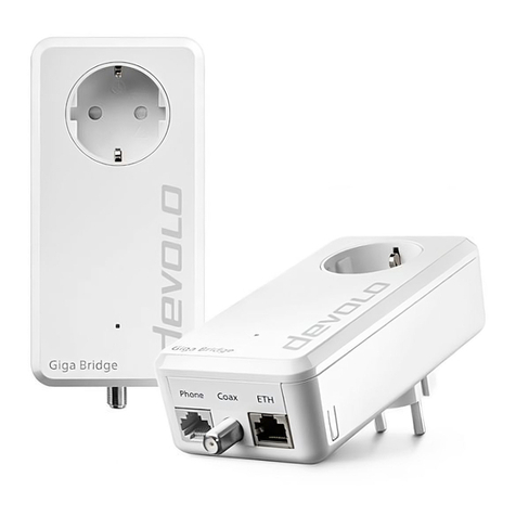
The devolo Giga Bridge features
bone gigabit network connection (ETH)
a for connecting the NT/ONT to the
devolo Giga Bridge adapter or the
devolo Giga Bridge adapter to the router
(expansion of the Ethernet WAN connec-
tion)
or
a for connecting the router to the
devolo Giga Bridge adapter or the
devolo Giga Bridge adapter to a device with
an Ethernet port in order to establish a con-
nection to the router (expansion of the
internal home network)
ba G.hn phone line socket for connection to the
telephone line (phone),
bone F-connector for connection to the coaxial
line (75 ohm)
bone LED indicator light
The LED status display can be disabled. For
more information, refer to Chapter 4 Con-
figuration.
bone reset button with combined G.hn function
which can also be used for manual pairing (in
addition to the network jack),

Introduction 18
devolo Giga Bridge
2.4.1Reading the indicator light
The integrated LED indicates the status of the
devolo Giga Bridge with flashing and lighting be-
haviour:
G.hn
LED
Flashing behav-
iour
Meaning LED status display
(web interface*)
1 Red LED Lights up for up to
5 seconds.
Start-up process Cannot be disabled
2 Red LED Flashes at inter-
vals of
0.5 seconds. (On/
off)
Status 1:
The adapter reset was successful. The
reset button has been pressed and held
for 10 seconds.
Status 2:
The adapter is (back) in factory default
condition. Since the last reset, no pairing
with another devolo Giga Bridge adapt-
er has taken place.
Connect the adapter to a different
devolo Giga Bridge adapter as a full-
fledged G.hn network, as described in
Chapter 3.3 Pairing – Establishing a
G.hn connection.
Cannot be disabled

19 Introduction
devolo Giga Bridge
3RedLEDLightsupsteady Status 1:
The other network nodes are in standby
mode and cannot currently be accessed
over the mains supply. The LEDs of the
other devolo Giga Bridge adapters flash
white only for a short time.
Status 2:
The connection to the other network
nodes has been interrupted. The remote
station may have been removed or
there is a malfunction in the connection.
Can be disabled
4White
LED
Status 1:
Flashes at inter-
vals of 0.5 second
(On/off)
Status 2:
Flashes at inter-
vals of 1second
(on/off)
Status 1:
This devolo Giga Bridge adapter is in
pairing mode and the system is search-
ing for new devolo Giga Bridge adapt-
ers.
Status 2:
Someone triggered the "Identify device"
function on the web interface. This func-
tion identifies the devolo Giga Bridge
adapter being sought.
Cannot be disabled
G.hn
LED
Flashing behav-
iour
Meaning LED status display
(web interface*)

Introduction 20
devolo Giga Bridge
* Information about the web interface can be
found in Chapter 4 Configuration.
**Depending on the configuration, a
devolo Giga Bridge adapter switches to standby
mode after approximately 10 minutes if no active
network device (e.g. computer) is connected to the
network interface. As soon as the network device
(e.g. computer) connected to the network inter-
face is switched on again, your devolo Giga Bridge
adapter can also be accessed again.
Check whether the adapter is connected to
the mains supply correctly and whether the
pairing operation has been carried out suc-
cessfully. For more information about this,
refer to 3.3 Pairing – Establishing a G.hn
connection.
5White
LED
Lights up steady The connection does not have any issues
and the devolo Giga Bridge adapters
are ready to operate.
Can be disabled
6White
LED
Flashes at inter-
vals of 0.1 sec.
on/ 3secoff
The devolo Giga Bridge adapter is in
standby mode.**
Can be disabled
7Redand
white
LED
Flashes at inter-
vals of 0.1 sec.
on/2sec.off
The data transmission rate is not in the
optimal range (PHY rate below 1Gbps)
Cannot be disabled
8Redand
white
LED
Flashes at inter-
vals of 0.5 sec.
red/0.5 sec.
white
The devolo Giga Bridge adapter is carry-
ing out a firmware update.
Cannot be disabled
G.hn
LED
Flashing behav-
iour
Meaning LED status display
(web interface*)
Other manuals for Giga Bridge
3
Table of contents
Other Devolo Network Hardware manuals

Devolo
Devolo dLAN 200 User manual

Devolo
Devolo Magic WiFi 2-1-1 User manual

Devolo
Devolo dLAN 200 AVpro User manual

Devolo
Devolo Kurulum User manual

Devolo
Devolo Magic Wi-Fi User manual

Devolo
Devolo Giga Bridge User manual

Devolo
Devolo Magic WiFi mini Multiroom Kiti User manual

Devolo
Devolo dLAN 1200+ WiFi ac User manual

Devolo
Devolo dLAN pro 1200 DINrail User manual

Devolo
Devolo Magic WiFi mini Ek User manual