DeWalt DW746 User manual

INSTRUCTION MANUAL
GUIDE D'UTILISATION
MANUAL DE INSTRUCCIONES
DW746, DW746X
Woodworker’s Table Saw
Scies circulaires à table d’entrepreneur
Sierra de banco para madera
INSTRUCTIVO DE OPERACIÓN, CENTROS DE
SERVICIO Y PÓLIZA DE GARANTIA. ADVERTENCIA:
LEASE ESTE INSTRUCTIVO ANTES DE USAR EL
PRODUCTO. SI TIENE DUDAS, POR FAVOR LLAME.
Before returning this
product call
1-800-4-DEWALT
IF YOU SHOULD EXPERIENCE A PROBLEM WITH
YOUR DEWALT PURCHASE,
CALL 1-800-4 DEWALT
IN MOST CASES, A DEWALT REPRESENTATIVE CAN RESOLVEYOUR
PROBLEM OVERTHE PHONE.
IFYOU HAVE A SUGGESTION OR COMMENT, GIVE US A CALL.
YOUR FEEDBACK ISVITALTOTHE SUCCESS OF DEWALT'S QUALITY
IMPROVEMENT PROGRAM.
See our catalog on the World Wide Web at www.dewalt.com


1
English
GROUNDED, CORD-CONNECTED MACHINES INTENDED FOR USE ON A SUPPLY
CIRCUIT HAVING A NOMINAL RATING LESS THAN 150 VOLTS
If the machine is intended for use on a circuit that has an outlet that looks like the one
illustrated in Fig. A, the machine will have a grounding plug that looks like the plug illus-
trated in Fig. A. A temporary adapter, which looks like the adapter illustrated in Fig. B,
may be used to connect this plug to a matching two-conductor receptacle as shown in
Fig. B if a properly grounded outlet is not available. The temporary adapter should be
used only until a properly grounded outlet can be installed by a qualified electrician. The
green-colored rigid ear, lug, and the like, extending from the adapter must be connected
to a permanent ground such as a properly grounded outlet box. Whenever the adapter
is used, it must be held in place with a metal screw.
GROUNDED
OUTLET
BOX
GROUNDING PIN
GROUNDING
MEANS
ADAPTER
GROUNDING PIN
ABC D
NOTE: In Canada, the use of a temporary adapter is not permitted by the Canadian
Electric Code.
DANGER: IN ALL CASES, MAKE CERTAINTHATTHE RECEPTACLE IN QUESTION IS
PROPERLY GROUNDED. IF YOU ARE NOT SURE, HAVE A QUALIFIED ELECTRICIAN
CHECK THE RECEPTACLE.
240 Volt, Single-Phase Operation
The motor supplied with your machine is a dual voltage, 120/240 volt motor. It is shipped
ready-to-run for 120 volt operation. However, it can be converted for 240 volt operation. A
qualified electrician should perform the conversion or take the machine to an authorized
DEWALT service center. When conversion is complete, the machine must conform to the
National Electric Code and all local codes and ordinances.
The machine is converted by rewiring the motor for 240 volts, installing a
240-volt plug on the power supply cord and replacing the switch (if neces-
sary) with one that is rated for 240-volt operation.
The saw with the 240-volt plug should ONLY be connected to an outlet
having the same configuration as the plug illustrated. No adapter is avail-
able or should be used with the 240-volt plug.
DANGER: IN ALL CASES, MAKE CERTAIN THAT THE RECEPTACLE
IN QUESTION IS PROPERLY GROUNDED. IFYOU ARE NOT SURE, HAVE A QUALIFIED
ELECTRICIAN CHECK THE RECEPTACLE.
Double Insulation
If saw is of double-insulated construction, read the following instructions.
Double insulated tools are constructed throughout with two separate layers of electrical
insulation or one double thickness of insulation between you and the tool’s electrical system.
Tools built with this insulation system are not intended to be grounded. As a result, your tool
is equipped with a two prong plug which permits you to use extension cords without concern
for maintaining a ground connection.
NOTE: Double insulation does not take the place of normal safety precautions when oper-
ating this tool. The insulation system is for added protection against injury resulting from a
possible electrical insulation failure within the tool.
Definitions: Safety Guidelines
The definitions below describe the level of severity for each signal word. Please read
the manual and pay attention to these symbols.
DANGER: Indicates an imminently hazardous situation which, if not avoided, will
result in death or serious injury.
WARNING: Indicates a potentially hazardous situation which, if not avoided, could
result in death or serious injury.
CAUTION: Indicates a potentially hazardous situation which, if not avoided, may
result in minor or moderate injury.
CAUTION: Used without the safety alert symbol indicates a potentially hazardous
situation which, if not avoided, may result in property damage.
IF YOU HAVE ANY QUESTIONS OR COMMENTS ABOUT THIS OR ANY DEWALT
TOOL, CALL US TOLL FREE AT: 1-800-4-DEWALT (1-800-433-9258)
General Safety Rules
WARNING: Read all instructions before operating product. Failure to follow all
instructions listed below may result in electric shock, fire and/or serious injury.
SAVE THESE INSTRUCTIONS
WARNING: FOLLOW ALL WIRING CODES and recommended electrical connections to
prevent shock or electrocution.
Grounding Instructions
If saw is of grounded construction, read the following instructions.
DANGER: SHOCK HAZARD. THIS MACHINE MUST BE GROUNDED WHILE IN USE.
SERIOUS INJURY COULD RESULT.
ALL GROUNDED, CORD-CONNECTED MACHINES
In the event of a malfunction or breakdown, grounding provides a path of least resis-
tance for electric current to reduce the risk of electric shock. This machine is equipped
with an electric cord having an equipment-grounding conductor and a grounding plug.
The plug must be plugged into a matching outlet that is properly installed and grounded
in accordance with all local codes and ordinances. Do not modify the plug provided - if it
will not fit the outlet, have the proper outlet installed by a qualified electrician. Improper
connection of the equipment-grounding conductor can result in risk of electric shock.
The conductor with insulation having an outer surface that is green with or without yel-
low stripes is the equipment-grounding conductor. If repair or replacement of the electric
cord or plug is necessary, do not connect the equipment-grounding conductor to a live
terminal. Check with a qualified electrician or service personnel if the grounding instruc-
tions are not completely understood, or if in doubt as to whether the machine is properly
grounded. Use only three-wire extension cords that have three-prong grounding type
plugs and matching three-conductor receptacles that accept the machine’s plug, as
shown in Fig. A. Repair or replace damaged or worn cord immediately.

2
English
• ANSI Z87.1 eye protection (CAN/CSA Z94.3)
• ANSI S12.6 (S3.19) hearing protection
• NIOSH/OSHA respiratory protection.
• DO NOT OVERREACH. Keep proper footing and balance at all times. Loss of balance
may cause personal injury.
• MAINTAIN TOOLS WITH CARE. Keep blades sharp and clean for best and safest
performance. Follow instructions for lubricating and changing accessories. Poorly main-
tained blades and machines can further damage the blade or machine and/or cause
injury.
• TURN THE MACHINE “OFF”, AND DISCONNECT THE MACHINE FROM THE
POWER SOURCE before installing or removing accessories, before adjusting or
changing set-ups, when making repairs or changing locations. Do not touch the plug’s
metal prongs when unplugging or plugging in the cord. An accidental start-up can cause
injury.
• REDUCE THE RISK OF UNINTENTIONAL STARTING. Make sure that the switch is
in the “OFF” position before plugging in the power cord. In the event of a power failure,
move the switch to the “OFF” position. An accidental start-up can cause injury.
• USE RECOMMENDED ACCESSORIES. Use only accessories that are recommended
by the manufacturer for your model. Accessories that may be suitable for one tool may
be hazardous when used on another tool. Consult the instruction manual for recom-
mended accessories. The use of improper accessories may cause risk of injury to
persons.
• NEVER STAND ONTOOL. Serious injury could occur if the tool is tipped or if the cutting
tool is unintentionally contacted.
• CHECK FOR DAMAGED PARTS. Before further use of the tool, a guard or other part
that is damaged should be carefully checked to determine that it will operate properly
and perform its intended function—check for alignment of moving parts, binding of
moving parts, breakage of parts, mounting and any other conditions that may affect
its operation. A guard or other part that is damaged should be properly repaired or
replaced. Do not use tool if switch does not turn it on and off. Damaged parts can cause
further damage to the machine and/or personal injury.
• DIRECTION OF FEED. Feed work into a blade or cutter against the direction of rotation
of the blade or cutter only.
• NEVER LEAVE TOOL RUNNING UNATTENDED. TURN POWER OFF. Don’t leave
tool until it comes to a complete stop. Serious injury can result.
• DO NOT OPERATE ELECTRIC TOOLS NEAR FLAMMABLE LIQUIDS OR IN
GASEOUS OR EXPLOSIVE ATMOSPHERES. Motors and switches in these tools may
spark and ignite fumes.
• STAY ALERT, WATCH WHAT YOU ARE DOING AND USE COMMON SENSE. DO
NOT USE THE MACHINE WHEN YOU ARE TIRED OR UNDER THE INFLUENCE OF
DRUGS, ALCOHOL OR MEDICATION. A moment of inattention while operating power
tools may result in serious injury.
• DO NOT ALLOW FAMILIARITY (gained from frequent use of your saw) TO
REPLACE SAFETY RULES. Always remember that a careless fraction of a second is
sufficient to inflict severe injury.
Additional Safety Rules for Table Saws
• AVOID AWKWARD POSITIONS, where a sudden slip could cause a hand to move into
a saw blade or other cutting tool.
• NEVER REACH IN BACK OF, OR AROUND,THE CUTTING TOOL with either hand to
hold down the workpiece.
POLARIZED PLUGS
To reduce the risk of electric shock, this equipment has a polarized plug (one blade is wider
than the other).This plug will fit in a polarized outlet only one way. If the plug does not fit fully
into the outlet, reverse the plug. If it still does not fit, contact a qualified electrician to install
the proper outlet. Do not change the plug in any way.
Important Safety Instructions
• TO REDUCE THE RISK OF KICKBACK AND OTHER INJURIES, KEEP GUARDS IN
PLACE and in working order.
• REMOVE ADJUSTING KEYS AND WRENCHES. Form habit of checking to see that
keys and adjusting wrenches are removed from spindle before turning tool on. Tools,
scrap pieces and other debris can be thrown at high speed, causing injury.
• KEEP WORK AREA CLEAN. Cluttered areas and benches invite accidents.
• DO NOT USE THE MACHINE IN A DANGEROUS ENVIRONMENT. The use of power
tools in damp or wet locations or in rain can cause shock or electrocution. Keep your
work area well-lit to avoid tripping or placing arms, hands and fingers in danger.
• KEEP CHILDREN AWAY. All visitors should be kept at a safe distance from work area.
Your shop is a potentially dangerous environment.
• MAKE WORKSHOP CHILDPROOF with padlocks, master switches, or by removing
starter keys. The unauthorized start-up of a machine by a child or visitor may result in
injury.
• DO NOT FORCE TOOL. It will do the job better and be safer at the rate for which it was
designed.
• USE RIGHT TOOL. Don’t force tool or attachment to do a job for which it was not
designed. Using the incorrect tool or attachment may result in personal injury.
• USE PROPER EXTENSION CORD. Make sure your extension cord is in good condi-
tion. If your product is equipped with a cord set, use only three-wire extension cords
that have three-prong grounding-type plugs and three-pole receptacles that accept the
tool’s plug. When using an extension cord, be sure to use one heavy enough to carry
the current your product will draw. An undersized cord will cause a drop in line voltage
resulting in loss of power and overheating.The following table shows the correct size to
use depending on cord length and nameplate ampere rating. If in doubt, use the next
heavier gauge. The smaller the gauge number, the heavier the cord.
MINIMUM GAUGE FOR CORD SETS
Volts Total Length of Cord in Feet
120V 0-25 26-50 51-100 101-150
240V 0-50 51-100 101-200 201-300
Ampere Rating
More Not more AWG
ThanThan
0 - 6 18 16 16 14
6 - 10 18 16 14 12
10 - 12 16 16 14 12
12 - 16 14 12 Not Recommended
• WEAR PROPER APPAREL. No loose clothing, gloves, neckties, rings, bracelets or
other jewelry to get caught in moving parts. Non-slip footwear is recommended. Wear
protective hair covering to contain long hair. Air vents may cover moving parts and
should also be avoided.
• ALWAYS USE SAFETY GLASSES. Everyday eyeglasses are NOT safety glasses.
Also use face or dust mask if cutting operation is dusty. ALWAYS wear certified safety
equipment:

3
English
• KEEP ARMS, HANDS AND FINGERS AWAY from the blade to prevent serious injury.
• USE A PUSH STICK OR PUSH BLOCK THAT IS APPROPRIATE TOTHE APPLICA-
TION TO PUSH WORKPIECES THROUGH THE SAW. A push stick is a wooden or
non-metallic stick, usually homemade, that should be used whenever the size or shape
of the workpiece would cause you to place your hands within six inches of the blade.
Use hold-downs, jigs, fixtures or feather boards to help guide and control the
workpiece when the guard cannot be used. Use saw-blade guard and spreader for
every operation for which it can be used, including all through sawing.
• DO NOT PERFORM RIPPING, CROSSCUTTING OR ANY OTHER OPERATION
FREEHAND.
• NEVER reach around or over saw blade.
• STABILITY. Make sure the table saw is firmly mounted to a secure surface before use
and does not move. If the mobility kit is installed, raise the moveable caster(s) so saw
is in its stationary position.
• NEVER CUT FERROUS METALS (those with any iron or steel content) or masonry.
Damage to the saw and personal injury may result.
• THE PROPER THROAT PLATE MUST BE IN PLACE AT ALL TIMES to reduce the
risk of a thrown workpiece and possible injury.
• USE THE CORRECT SAW BLADE FOR THE INTENDED OPERATION. The blade
must rotate toward the front of the saw. Always tighten the blade arbor nut securely.
Before use, inspect the blade for cracks or missing teeth. Do not use a damaged
blade.
• NEVER ATTEMPT TO FREE A STALLED SAW BLADE WITHOUT FIRST TURNING
THE MACHINE OFF. If a workpiece or cut-off piece becomes trapped inside the guard,
turn saw off and wait for blade to stop before lifting the guard and removing the piece.
• NEVER START THE MACHINE with the workpiece against the blade to reduce the risk
of a thrown workpiece and personal injury.
• NEVER run the workpiece between the fence and a molding cutterhead to reduce the
risk of a thrown workpiece and personal injury.
• AVOID AWKWARD OPERATIONS AND HAND POSITIONS where a sudden slip
could cause a hand to move into the blade.
• NEVER have any part of your body in line with the path of the saw blade. Personal
injury will occur.
• NEVER PERFORM LAYOUT, ASSEMBLY OR SET-UP WORK on the table/work area
when the machine is running. A sudden slip could cause a hand to move into the blade.
Severe injury can result.
• CLEAN THE TABLE/WORK AREA BEFORE LEAVING THE MACHINE. Lock the
switch in the “OFF” position to prevent unauthorized use.
• DO NOT leave a long board (or other workpiece) unsupported so the spring of
the board causes it to shift on the table resulting in loss of control and possible
injury. Provide proper support for the workpiece, based on its size and the type of
operation to be performed. Hold the work firmly against the fence and down against
the table surface. If supports are attached to the saw, be certain saw will not tip under
load.
• DO NOT OPERATE THIS MACHINE until it is completely assembled and installed
according to the instructions. A machine incorrectly assembled can cause serious
injury.
• OBTAIN ADVICE from your supervisor, instructor or another qualified person if you are
not thoroughly familiar with the operation of this machine. Knowledge is safety.
• ADDITIONAL INFORMATION regarding the safe and proper operation of power
tools (i.e., a safety video) is available from the Power Tool Institute, 1300 Sumner
Avenue, Cleveland, OH 44115-2851 (www.powertoolinstitute.com). Information is also
available from the National Safety Council, 1121 Spring Lake Drive, Itasca, IL 60143-
3201. Please refer to the American National Standards Institute ANSI 01.1 Safety
Requirements for Woodworking Machines and the U.S. Department of Labor OSHA
1910.213 Regulations.
TERMS: THE FOLLOWING TERMS WILL BE USED THROUGHOUT THE MANUAL
AND YOU SHOULD BECOME FAMILIAR WITH THEM.
• Through-sawing refers to any cut that completely severs the workpiece.
• Push Stick refers to a wooden stick, usually homemade, that is used to push small
workpiece through the saw and keeps the operator’s hands clear of the blade.
• Kickback occurs when the saw blade binds in the cut and violently thrusts the work-
piece back toward the operator.
• Freehand refers to cutting without the use of a miter gauge or rip fence or any other
means of guiding or holding the workpiece other than the operator’s hand.
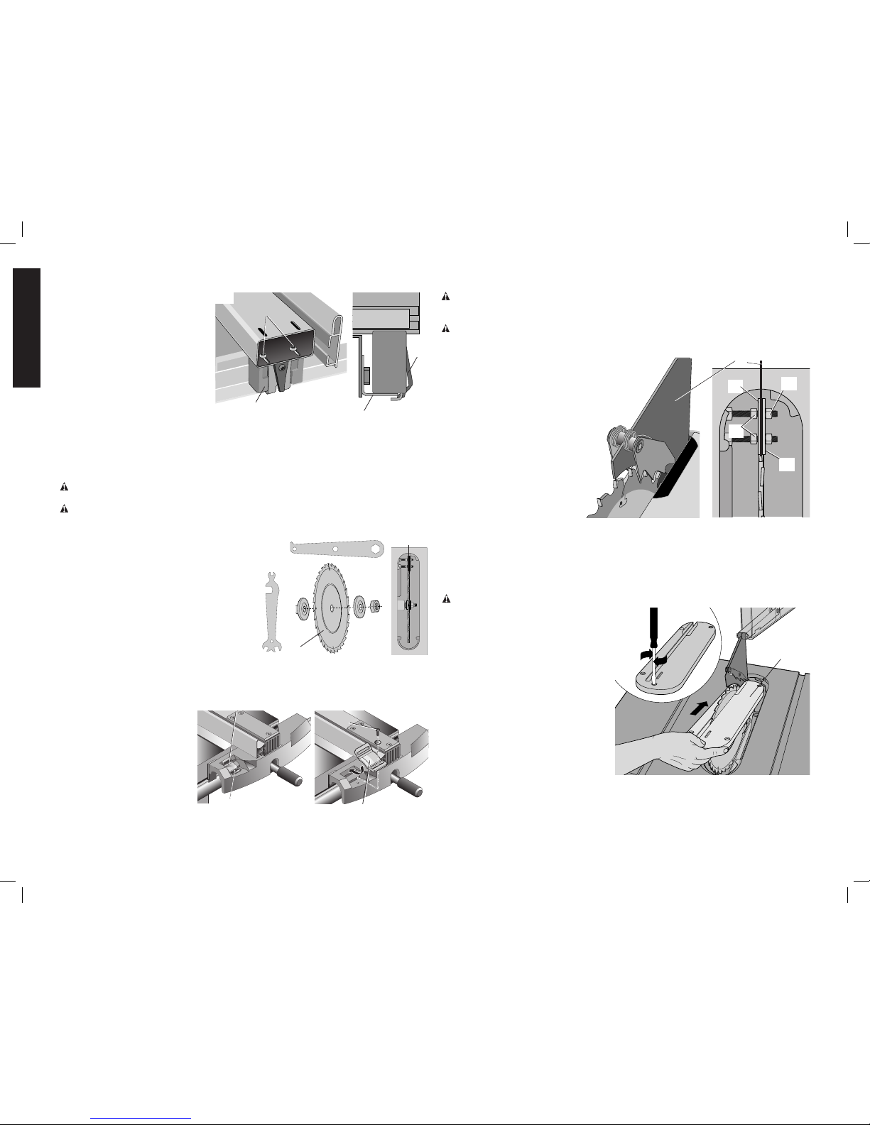
SAW BLADE GUARD AND SPREADER
Your table saw is equipped with a blade guard and spreader assembly that covers the blade
and prevents accidental contact. The spreader is a flat plate that fits into the cut made by
the saw blade and effectively fights kickback by lessening the tendency of the blade to bind
in the cut. The spreader can only be used when making through cuts that sever the wood.
When making dadoes, rabbits and other cuts that make less than through cuts, the blade
guard and spreader assembly must be removed from the saw. Two anti-kickback pawls are
located on the sides of the spreader that allow the wood to pass through the blade in the
cutting direction but lock it if it tries to move backwards toward the operator.
MAKING A PUSH STICK (INSIDE BACK COVER)
WARNING: When ripping work less than 6" (152 mm) wide, a push stick should be used
to complete the feed and could easily be made from scrap material by following the pattern
on the inside back cover.
• In order to operate your table saw safely you must use a push-stick whenever the size
or shape of the workpiece would cause your hands to be within 6" (152 mm) of the saw
blade or other cutter.
• No special wood is needed to make a push-stick as long as it’s sturdy and long enough.
A length of 12" (305 mm) is recommended with a notch that fits against the edge of the
workpiece to prevent slipping. It’s a good idea to have several push sticks of the same
length [12" (305 mm)] with different size notches for different workpiece thicknesses.
• See the inside back cover for a picture of a push stick. The shape can vary to suit your
own needs as long as it performs its intended function of keeping your hands away from
the blade.
KICKBACKS
How to Avoid Them and Protect Yourself from Possible Injury
a. Be certain that the rip fence is parallel to the saw blade.
b. Do not rip by applying the feed force to the section of the workpiece that will become
the cut-off (free) piece. Feed force when ripping should always be applied between the
saw blade and the fence; use a push stick for short work, 6" (152 mm) wide or less. For
less than 2" (51 mm) wide, you must use a special fixture.
c. Keep saw blade guard, splitter and anti-kickback teeth in place and operating properly.
Keep teeth sharp. If teeth are not operational, return your unit to the nearest authorized
DEWALT service center for repair. The splitter must be in alignment with the saw blade
and the teeth must stop a kickback once it has started. Check their action before ripping
by pushing the wood under the anti-kickback teeth. The teeth must prevent the wood
from being pulled toward the front of the saw.

4
English
d. Plastic and composition (like hardboard) materials maybe cut
on your saw. However, since these are usually quite hard and
slippery, the anti-kickback pawls may not stop a kickback.
Therefore, be especially attentive to following proper set up and
cutting procedures for ripping.
e. Use saw blade guard and splitter for every operation for which it
can be used, including all through-sawing.
f. Push the workpiece past the saw blade prior to release.
g. NEVER rip a workpiece that is twisted or warped, or does not have
a straight edge to guide along the fence.
h. Use featherboards when the anti-kickback device or the guard and
splitter cannot be used.
i. NEVER sawing a large workpiece that cannot be controlled.
j. NEVER use the fence as a guide or length stop when
crosscutting.
k. NEVER saw a workpiece with loose knots, flaws, nails or other
foreign objects.
l. NEVER rip a workpiece shorter than 10" (254 mm).
WARNING: Some dust created by power sanding, sawing, grinding,
drilling, and other construction activities contains chemicals known to
the State of California to cause cancer, birth defects or other reproduc-
tive harm. Some examples of these chemicals are:
• lead from lead-based paints,
• crystalline silica from bricks and cement and other masonry
products, and
• arsenic and chromium from chemically-treated lumber (CCA).
Your risk from these exposures varies, depending on how often you do
this type of work. To reduce your exposure to these chemicals: work
in a well-ventilated area and work with approved safety equipment,
such as those dust masks that are specially designed to filter out
microscopic particles.
• Avoid prolonged contact with dust from power sanding, saw-
ing, grinding, drilling and other construction activities. Wear
protective clothing and wash exposed areas with soap and
water. Allowing dust to get into your mouth, eyes or lay on the skin
may promote absorption of harmful chemicals.
WARNING: Use of this tool can generate and/or disburse dust,
which may cause serious and permanent respiratory or other injury.
Always use NIOSH/OSHA approved respiratory protection appropri-
ate for the dust exposure. Direct particles away from face and body.
Always operate tool in well-ventilated area and provide for proper dust
removal. Use dust collection system wherever possible.
SAVE THESE INSTRUCTIONS
FOR FUTURE USE
Hardware Included with the DW746 Woodworker’s Table Saw
BOLT
10 MM X 35 MM
(2 PIECES)
BOLT
10 MM X 25 MM
(8 PIECES)
CARRIAGE BOLT
8 MM X 20 MM
(4 PIECES)
T50 TORX
FLAT HEAD SCREW
10 MM X 30 MM
(4 PIECES)
FLAT WASHER
(14 PIECES)
10 MM LOCK WASHER
(14 PIECES)
8 MM LOCK WASHER
(4 PIECES)
5 mm
HEX
WRENCH
( 1 )
T50
TORX
WRENCH
(1)
M 10 NUT
16 mm HEX
(8 PIECES)
M 8 NUT
13 MM HEX
(4 PIECES)
WRENCH
HOOK
(1)
PARTS SHOWN ARE
FULL SIZE - EXTRA
FASTENERS MAY HAVE
BEEN INCLUDED

5
English
Specifications
Horsepower 1-3/4
Table Size 27" x 40-3/4"
Miter Angle 60° L&R
Bevel Angle -2° to 47° Left
Blade Size 10" (254 mm)
Max. Cut Depth 0° Bevel............... 3-1/8" (79 mm)
Max. Cut Depth 45° Bevel............. 2-1/8" (54 mm)
RPM, no load 3000
DW746 Basic Unit
Always follow the instructions included with the acces-
sory when asssembling custom accessories to this unit.
Assemble any accessories first.
Tools Included
To aid you with assembly of your new saw, we have included
the following tools.
• T50 torx wrench
• 5 mm hex wrench
• Combination wrench with 16 mm, 13 mm, 10 mm
and 22 mm openings
• Blade wrench with 15/16" and 10 mm box ends.
Tools You Will Need to Supply
• Flat blade screwdrivers
• 16 mm or 5/8" open end wrench or pliers
• Ruler
• Square
• Soft hammer, or regular hammer and block of wood
TO SPEED ASSEMBLY, THE FOLLOWING WOULD BE
HELPFUL:
• 16 mm or 5/8" socket wrench, with 6" extension
• 13 mm or 1/2" socket wrench
• 10 mm open end wrench
• T20 and T25 Torx drivers
• T40 Torx wrench.
YOUR WILL ALSO NEED:
• Mild solvent cleaner such as mineral spirits, paint thinner or denatured alcohol.
• High-quality paste wax
Necessary Hardware
Your hardware bag, located in the parts box, contains all the necessary nuts, bolts and
washers to assemble the components included with the DW746 Woodworker’s Table Saw.
To make assembly of your saw easier, match the nuts, bolts and washers with the chart on
the previous page. Separate them by size so that you can easily locate the item you need.
Before each step, check your hardware against the chart and identify the pieces you need.
FEATURES (Fig. 1)
Examine Figure 1 to become familiar with the saw and its various parts. The following sec-
tions on assembly and adjustments will refer to these terms and you must know what and
where the parts are.
A. Rear fence rail (included with DW746X)
B. Table top
C. Splitter
D. Blade
E. Blade guard
F. Fence face
G. Rip fence
H. Fence beam
I. Rail lock lever
J. Motor cover
K. Wrench hook
L. Adjustable feet
M. Blade height adjustment wheel
N. Power cord
O. On/Off Switch
P. Blade tilt crank
Q. Front Fence Rail
(included with DW746X)
R. Miter gauge
S. Motor
T. Dust collection port
U. Rip scale pointer
V. Side support table
W. Miter slot
ST
AV
C
E
D
F
G
H
I
J
K
L
N
O
P
Q
R
M
U
WB
FIG. 1

6
English
Unpacking
WARNING: To reduce the risk of injury, do not connect the machine to the power
source until the machine is completely assembled and you read and understand the entire
instruction manual.
1. Remove parts box, motor cover, fence beam, side tables and fence rails (DW746X).
2. Turn the saw to the upright position.
CAUTION: Use a minimum of two people to prevent personal injury when turning the saw
and stand upright. The combined weight of the table top and motor assembly is approxi-
mately 200 lbs (91 kg).
3. Cut and remove plastic strap holding the motor.
4. Using front hand crank, lower the motor some and remove the foam packing material
between the motor and the mechanism.
Assembly
WARNING: To reduce the risk of injury, do not connect the machine to the power
source until the machine is completely assembled and you read and understand the entire
instruction manual.
PLEASE READ ENTIRE ASSEMBLY SECTION BEFORE PROCEEDING.
INSTALL BEVEL CRANK (FIG. 2)
1. Install the blade height adjustment wheel (M) M
AA
BB
FIG. 2
over the shaft (AA), rotate it slightly to fully
engage the shaft pin.
2. Screw the lock knob (BB) into place until it is
fully seated, then back it off 1/4 to 1/2 turn.
3. Turn blade height adjustment wheel (M) to raise
mechanism as high as it will go.
INSTALL WRENCH HOOK (FIG. 3)
NOTE: Always hang the blade wrench, spindle lock
wrench and push stick on wrench hook when not in use.
1. Located the plastic threaded insert at the top of the front right leg.
2. Thread the “L” shaped wrench hook (K) in until only a few threads are K
FIG. 3
visible.
ASSEMBLE FRONT RAIL AND BRACKETS (FIG. 4)
IMPORTANT: DW746X includes a 30" precision fence rail system. A 30" or
52" precision rail system for the DW746 may be purchased at additional cost. Always fol-
low the instructions included with the accessory. After assembling the rail system, refer to
Parallel the Rails to the Table Top.
If you need assistance with this accessory, please call 1-800-4-DEWALT (1-800-433-9258)
or visit our website www.dewalt.com.
You will Need: 4 – 8 mm Carriage Bolts
4 – 8 mm Lock Washers
4 – 8 mm Nuts
1. Unpack rail carton (contains front and rear rail).
2. Place the carriage bolts into each rail bracket (CC) as
FIG. 4
DD
CC
shown.
3. Place lock washers and nuts onto carriage bolts and
tighten the nuts a few threads.
4. Place the head of the carriage bolt into keyhole slots in
the front rail and slide to engage the square part of the
bolt. Make sure the rip scale (DD) on the front rail and all
four brackets are facing up.
5. Tighten nut finger tight.
6. Repeat for other three brackets.
ATTACH FRONT RAIL WITH BRACKETS TO THE TABLE TOP (FIG. 5)
You will need: 2 – 10 x 30 mm Flat Head FIG. 5
CC
B
CC
Screws
2 –10 mm Flat Washers
2 – 10 mm Lock Washers
2 – 10 mm Nuts
1. Secure each screw through the upper hole
in the center rail brackets (CC) keeping the
flat washer, lock washer and nut on the
inside of the table (B).
2. Tighten snug, do not overtighten. Tighten
center rail bracket nuts, leaving the outer
nuts finger tight.
ATTACH REAR RAIL TO THE TABLE TOP (FIG. 6)
You will need: 2 – 10 x 35 mm
Hex Head Bolts
2 – 10 mm Flat Washers
2 – 10 mm Lock Washers
2 – 10 mm Nuts
1. Secure rear fence rail (A) to FIG. 6
A
B
A
B
table top (B) using hex head
bolts, washers, lock washers
and nuts. Keep the washers
and nuts on the inside of the
table. The flat side should be
down unless you are also
mounting an accessory
(consultaccessoryinstructions
for rail mounting details).Make
sure ends of the rear rail line
up with the ends of the
front rail.
2. Tighten snug, do not overtighten.
PARALLEL THE RAILS TO THE TABLE TOP (FIG. 7)
1. Use the fence face (F) to extend the table FIG. 7
F
QA
surface over the front fence rail (Q).
2. Use a ruler to measure the distance between
the table top and the rail at both ends of the
table top. The distance should be equal at
both ends.
3. If adjustment is needed, loosen the mount-
ing screws slightly and tap on the rail brack-
ets with a soft hammer or regular hammer
and a block of wood until the distances are the same.
4. Tighten fasteners securely.
5. Repeat for the rear fence rail (A).

7
English
ASSEMBLE THE FENCE BEAM TO THE FENCE HEAD FIG. 10 G
H
JJ
HH
(FIG. 10).
1. Remove the three flat head screws (HH) securing the
cover plate (JJ) to the fence beam with the T50 Torx
wrench.
2. Turn the rip fence (G) upside down. Slide the fence
beam (H) into the rip fence as shown.
3. Flip the fence beam over and install the cover plate
and three screws. Tighten snug, do not overtighten.
ADJUSTING FENCE TO TABLE TOP (FIG. 11)
IMPORTANT: Check alignment of beam and fence face
before each cutting session.
ALIGNING THE RIP FENCE
1. Place the fence face (F) on the
HH
I
KK
W
FIG. 11 F
Q
front rail (Q) and rear rail (A)
close to the miter slot (W) at
the right-hand side of the
table.
2. Loosen the three locking knobs
(KK). Allow the fence face to
rest on the table top, then tight-
en the locking knobs (KK).
3. Slightly loosen the three screws
(HH).
4. Slide the fence and adjust the
beam angle until the fence
face is in line with the miter
slot (W).
5. Lock the fence beam (H) in
place by pushing the rail lock-
ing lever (I) down.
6. Tighten the locking knobs (KK),
starting with the rearmost two.
ADJUSTING THE FENCE FACE
(FIG. 12)
1. Loosen the locking knobs (KK).
2. Set the fence face (F) so it clears the
FIG.12 KK
F
B
table top (B) by approx. 1/16"
(1.6 mm).
3. If desired, adjust the fence face for-
ward or backward.
4. Tighten the locking knobs (KK).
NOTE: For very thin workpieces, the
fence face can be set so it rests on the
table top. Make sure to set the fence
face so it clears the table top by approxi-
mately. 1/16" (1.6 mm) before moving
the fence.
ATTACH THE LEFT & RIGHT SIDE SUPPORT TABLES (FIG. 8)
You will need: 6 – 10 x 25 mm Hex Head Bolts
6 – 10 mm Flat Washers
6 – 10 mm Lock Washers
1. Installthe threebolts,flat washers FIG. 8
VFF
B
and lock washers in the holes in
the side of the table top (B) as
shown. Keep a 1/4" (6.4 mm)
gap between the table top and
bolt heads.
2. Slide the side support table (V)
on the bolts, fitting into the
notches (FF). Do tighten nuts.
3. Use the fence face as a guide
to flush the support table to the
main table edge and snug the
front bolt. Repeat this process
for the rear bolt.Tighten the cen-
ter bolt.
4. Repeat on the other side.
ATTACH FRONT AND REAR RAILS TO SUPPORT TABLES (FIG. 9)
You will need for front rail:
2 – 10 x 30 mm Flat Head Screws
2 – 10 mm Flat Washers
2 – 10 mm Lock Washers
2 – 10 mm Nuts
You will need for rear rail:
2 – 10 x 25 mm Hex Head Bolts
2 – 10 mm Flat Washers
2 – 10 mm Lock Washers
2 – 10 mm Nuts
1. Align front rail brackets (CC) with the side FIG. 9 CC
GG
support table (V) and tighten bracket nuts
(GG) to the rail.
2. Attach the support table to the outer front
rail brackets with the screws, flat washers,
lockwashers and nuts. Keep the washers
and nut on the inside of the table.
3. Attach the support table to the outer
rear rails with the bolts, flat washers,
lockwashers and nuts, Keep the washers
and nut on the inside of the table.
4. Using the fence face as a straight edge
make sure the support table is level with
or slightly below the table top. Adjust if
needed and tighten all fasteners.
5. Repeat this procedure for the other sup-
port table.

8
English
ADJUSTING THE REAR FENCE GLIDE (FIG. 13)
1. Slide the rip fence (G) back FIG.13
MM
LL
NN
A
and forth to check if it slides
freely over the rails.
2. Lock the rip fence in place
using the rail locking lever (I).
If there is excessive up/down
movement in the rear of the fence
when locking, the rear fence
bracket (LL) needs adjustment.
To adjust:
1. Loosen the screws (MM).
2. Set the retaining clip (NN) so
that it slightly pushes on the rear rail (A).
3. Tighten the screws.
4. Ensure the fence still slides smoothly. If it does not, the retaining clip (NN) is pushing on
the rear rail (A) too strongly.
TO INSTALL THE SAW BLADE (FIG.14)
WARNING: Use ONLY 10" (254 mm) diameter blades with 5/8" (16 mm) arbor holes,
rated at 3600rpm or higher.
WARNING: To reduce the risk of injury. Wear gloves when handling saw blades.
1. Set the blade arbor highest position
SPINDLE
LOCK
WRENCH
BLADE WRENCH
FIG. 14
OO
PP
QQ
D
using the blade height adjustment
wheel (M).
2. Remove the nut (OO) and outer clamp
washer (PP)
3. Place the blade (D) onto the arbor with
the teeth pointing towards the front of
the saw.
4. Remount the outer clamp washer (PP)
and nut (OO) as shown. Make sure
that the saw blade is piloted on the
outer clamp washer hub (QQ).
5 Use the spindle lock wrench and blade
wrench to tighten the nut.
NOTE: If the nut fall into the interior of the saw, carefully remove it though the dust port.
ADJUST THE FENCE SCALE INDICATOR (FIG. 15).
1. Slide the fence until it just FIG. 15
RR
U
U
RR
touches the blade.
2. Loosen the fence indicator
screw (RR) and slide it until
the hairline aligns with the “0”
line on the scale.
3. Tighten the screw.
4. If the low profile fence face
accessory or a wider home-
made fence face is used
which is out of the adjust-
ment range of the pointer, the
pointer (U) can be removed completely, turned 180 degrees, re-installed, and aligned
with the “0” line.
INSTALL THE GUARD AND SPLITTER ASSEMBLY (FIG. 16)
CAUTION: To prevent snagging of the workpiece, the table insert should be flush or
slightly below the surface of the table top and secured in place. The rear of the throat plate
should be flush or slightly above the table top. Refer to Install and Adjust Throat Plate.
CAUTION: When installing the throat plate, always make certain to hold on to the blade
guard. The insert will automatically release the holding action on the splitter and lower the
blade guard when it is installed in the table opening.
1. Raise the blade to its highest
TT
TT
C
UU
FIG. 16
SS
point.
2. Loosen the outer guard
retaining nuts (SS) enough so
the splitter (C) will fit between
the two guard retaining plates
(TT).
3. Install the splitter (C).
4. Using a straight edge, check
to ensure the splitter is prop-
erly aligned with the blade. If
not, the position is adjusted
by moving the inner guard
clamp nuts (UU) to change
the location the splitter. Make
sure there is some clearance
between the splitter and the blade and the blade spins freely. If the splitter is tilted rela-
tive to the blade, the splitter plate can be bent until it lines up correctly. IMPORTANT:
THE GUARD SHOULD BE IN PLACE FOR ALL POSSIBLE CUTS. When making non-
through cuts, the guard can be easily removed by slightly loosening the outer guard nuts
(SS). The guard can easily be replaced without having to readjust the inner nuts.
INSTALL AND ADJUST THE THROAT PLATE (FIG. 17)
CAUTION: To reduce the risk of injury. The throat plate must be in place at all times.
1. Align the throat plate (VV) as shown FIG. 17
VV
and insert the tabs on the back of the
throat plate into the holes at the back
of the table and lower the plate into its
opening.
2. The throat plate includes four adjust-
ment screws which raise or lower it.
When properly adjusted, the front
of the throat plate should be flush
or slightly below the surface of the
table top, and the rear of the throat
plate should be flush or slightly above
the table top. The center front screw,
when turned clockwise, will engage
a cam under the front lip of the
table, locking the throat plate in place.
Rotate the screw counterclockwise
1/2 turn to remove the throat plate.

9
English
ADJUST THE BEVEL STOPS (FIG. 18)
1. Using a square, set the blade FIG. 18
to exactly “0” degrees. If the
blade stops beveling before it
gets to 0, loosen the stop set
screw (located in the left
miter guide slot) with the
5 mm hex wrench and then
proceed to “0” degrees. With
the blade set at 0, slowly turn
the zero stop screw in until
you feel resistance. Bevel the
blade away from 0 a little
then back to the stop.
2. Remeasure the angle and repeat the stop adjustment as necessary until the blade
stops at 0 degrees.
3. Set the 45 stop the same way. The set screw for the 45° stop is located in the right
hand miter guide slot.
For some special cuts, the stops can be backed out and the saw will bevel from –2 degrees
to 47 degrees.
ADJUST THE BEVEL SCALE (FIG. 19)
1. Bevel the saw until it hits the FIG. 19
BB
M
WW
XX
XX
zero bevel stop.
2. Remove the lock knob (BB)
and blade height adjustment
wheel (M).
3. Adjust the red pointer by
loosening the screw (WW)
where it attaches to its shaft,
move the pointer until it lines
up with the 0 line on the
scale, and retighten the
screw. The pointer should
be positioned just barely off
of the scale surface.
4. Bevel the saw to the 45º stop. If the pointer doesn’t point to 45º, loosen the two screws
(XX) which hold the scale to the saw front panel and slide the scale up or down until
the pointer lines up with the 45 line. Retighten the scale screws.
5. Replace the blade height adjustment wheel and lock knob.
INSTALL THE MOTOR COVER (FIG. 20)
1. Remove the two cover screws and washers (YY) from FIG. 20
YY
J
the top of the two side legs with a small flat blade
screwdriver.
2. Snap the two bottom tabs of the cover (J) into the slots
in the right lower crossmember.
3. Place the cover in position and reinstall the screws and
washers.
LEVEL THE SAW (FIG. 21)
1. Place the saw in the location it is going to be used.
2. If the saw rocks on the floor, the foot not touching the floor can
FIG. 21
ZZ
L
be lowered to compensate for the uneven floor.
a. Loosen the two screws (ZZ) that hold the foot (L) to the leg.
Let the foot fall to the floor surface.
b. Retighten the screws holding the foot to the leg.
If your saw will have a permanent location, we recommend bolting
the feet to the floor using the holes provided.
ADJUSTMENT AND USE OF MITER GAUGE (FIG. 22)
Your miter gauge features adjustable
30
30
45
60
75
75
90
60
45
FIG. 22
A1
A2
A3
stops at 90° and 45° left and right.
To adjust these stops:
a. Loosen the lock nuts (A1) and
tighten or loosen the three
adjusting screws (A2).
b. Check the gauge with a square
against the blade and tighten
the three adjusting screws.
c. To set the miter gauge past
the 45 degree stops, flip up the
stop plate (A3) and continue to
the required angle.
CLEAN THE TABLE TOP
Your saw was shipped with a rust preventive coating which should be removed. Clean the top
with mineral spirits or denatured alcohol and apply paste wax. Apply and remove soon after-
ward to prevent a sticky build-up.
Rip Fence Operation
RAIL LOCK LEVER (FIG. 23)
The rail lock lever (I) locks the fence in place preventing movement during FIG. 23
I
cutting. To lock the rail lever, push it down and toward the rear of the
saw. To unlock, pull it up and toward the front of the saw.
NOTE: When ripping, always lock the rail lock lever.
RIP SCALE POINTER
NOTE: The rip scale pointer will need to be readjusted whenever a
thicker or thinner blade is installed. Should you decide to use a thicker
face, or the DEWALT low fence face accessory, the scale pointer may be
removed and turned 180° to line up with the scale. Refer to Adjust the
Fence Scale Indicator under Assembly.
RIP FENCE CAPACITY
The rip fence will slide beyond the end of the rails in either direction with-
out falling off. Stops are provided to keep the fence attached.

10
English
On-Off Switch (Fig. 24)
WARNING: To reduce the risk of injury, be sure switch is in the
FIG. 24
O
A4
OFF position before plugging machine in.
Lift the ON/OFF switch (O) paddle up to turn your saw ON and push
it down to turn your saw OFF.
A hole (A4) is provided in the switch for insertion of a padlock with
a removable shank to lock the saw off.
NOTE: A conventional padlock will not fit.
Saw Blades
CAUTION: Use ONLY 10" (254 mm) diameter blades with 5/8"
(16 mm) arbor holes, rated at 3600rpm or higher.
1. The saw blade furnished with your new saw is a 10" (254 mm) fine ripping blade, used
for ripping (with the grain) through the material, and occasional cross cuts. The center
hole to fit on the arbor is 5/8" (16 mm) diameter. This blade will produce a good quality
cut for many applications.
2. There are many types of blades available to do specific and special jobs such as
cross cut only, rip only, hollow ground, thin plywood, paneling, etc.
3. Use only saw blades designed for maximum safe operating speeds of 5,000 RPM or
greater.
4. Saw blades should always be kept sharp. It is recommended that you locate a repu-
table sharpening service to sharpen your blades when needed.
5. Never stack blades on top of one another to store. Place material such as cardboard
between them to keep the blades from coming in contact with one another.
CAUTION: Abrasive wheels should not be used on this saw.
Operation
WARNING: Before using the saw, verify the following each and every time:
1. ALWAYS wear proper eye, hearing and respiratory equipment.
2. Blade is tight.
3. Bevel angle and height lock knobs are tight.
4. If ripping, ensure rail fence lock lever is tight and fence is parallel to the blade.
5. If crosscutting, miter gauge knob is tight.
6. The blade guard is properly attached and the anti-kickback teeth are functioning.
7. ALWAYS inspect the guard and splitter for proper alignment operation and clearance with
saw blade.
Failure to adhere to these common safety rules can greatly increase the likelihood of injury.
WARNING: To reduce the risk of injury, turn unit off and disconnect machine from
power source before installing and removing accessories, before adjusting or changing set-
ups or when making repairs. An accidental start-up can cause injury.
WARNING: Before connecting the table saw to the power source or operating the saw,
always inspect the guard and splitter for proper operation alignment and clearance with saw
blade. Personal injury may result.
CAUTION: If your saw makes an unfamiliar noise or if it vibrates excessively, cease operating
immediately until the source has been located and the problem corrected.
CAUTION: The proper throat plate must be in place at all times to reduce the risk of a thrown
workpiece and possible injury.
THIS SAW IS NOT INTENDED FOR CUTTING METAL.
Cutting
WARNING: To reduce the risk of injury, turn unit off and disconnect machine from power
source before installing and removing accessories, before adjusting or changing set-ups or
when making repairs. An accidental start-up can cause injury.
WARNING: Before connecting the table saw to the power source or operating the saw,
always inspect the guard and splitter for proper operation alignment and clearance with saw
blade. Personal injury may result.
There are two basic types of cuts: ripping and crosscutting. In general, cutting with the
grain is ripping and across the grain is crosscutting. However, with man made materials this
distinction is somewhat difficult to make. Therefore, cutting a piece of wood to a different
width is ripping and cutting across the short dimension is crosscutting. Neither ripping or
crosscutting may be done safely freehand! Ripping requires the use of the rip fence and
crosscutting uses the miter gauge.
Ripping
WARNING: To reduce the risk of injury, turn unit off and disconnect machine from
power source before installing and removing accessories, before adjusting or changing
set-ups or when making repairs. An accidental start-up can cause injury.
WARNING: Never touch the “free end” of the workpiece or a “free piece” that is cut off,
while the power is ON and/or the saw blade is rotating. Piece may contact the blade result-
ing in a thrown workpiece of possible injury
WARNING: Keep saw blade guard, splitter and anti-kickback teeth in place and operat-
ing properly. Keep teeth sharp. If teeth are not operational, return your unit to the nearest
authorized DEWALT service center for repair. The splitter must be in alignment with the saw
blade and the teeth must stop a kickback once it has started. Check their action before rip-
ping by pushing the wood under the anti-kickback teeth. The teeth must prevent the wood
from being pulled toward the front of the saw.
WARNING: A rip fence should ALWAYS be used for ripping operations to prevent loss
of control and personal injury. NEVER perform a ripping operation freehand. ALWAYS lock
the fence to the rail.
WARNING: When bevel ripping and whenever possible, place the fence on the side of
the blade so that the blade is tilted away from the fence and hands. Keep hands clear of the
blade and use a push stick to feed the workpiece if there is less than 6" (152 mm) between
the fence and the blade.
1. Lock the rip fence by pressing the rail lock lever down. Remove the miter gauge.
2. Raise the blade so it is about 1/8" (3.2 mm) FIG. 25
higher than the top of the workpiece.
3. Hold the workpiece flat on the table and against
the fence.Keep the workpiece about 1" (25.4 mm)
away from the blade.
CAUTION: The workpiece must have a straight
edge against the fence and must not be warped,
twisted or bowed. Keep both hands away from the
blade and away from the path of the blade.
4. Turn the saw on and allow the blade to come up
to speed. Both hands can be used in starting the
cut. When there is approximately 12" (305 mm) left to be ripped, use only one hand,
with your thumb pushing the material, your index and second finger holding the material
down and your other fingers hooked over the fence. Always keep your thumb along side
your first two fingers and near the fence.
5. Keeping the workpiece against the table and fence, slowly feed the workpiece rearward
all the way through the saw blade. Continue pushing the workpiece until it is clear of the
guard and it falls off the rear of the table. Do not overload the motor.
6. NEVER try to pull the workpiece back with the blade turning. Turn the switch off, allow
the blade to stop, raise the anti-kickback teeth on each side of the splitter if necessary
and slide the workpiece out.

11
English
7. When sawing a long piece of material or a panel, always use a work support. A sawhorse,
rollers or out feed assembly provides adequate support for this purpose. The work sup-
port must be at the same height as the saw table.
Bevel Ripping
This operation is the same as ripping except the bevel angle is set to an angle other than
zero degrees.
WARNING: Before connecting the table saw to the power source or operating the saw,
always inspect the guard and splitter for proper alignment and clearance with saw blade.
Check alignment after each change of bevel angle.
Ripping Small Pieces
It is unsafe to rip small pieces.It is not safe to put your FIG. 26
hands close to the blade. Instead, rip a larger piece to
obtain the desired piece. When a small width is to be
ripped and the hand cannot be safely put between the
blade and the rip fence, use one or more push sticks.
A pattern is included on the inside back cover to make
push sticks. Use them to hold the workpiece against
the table and fence, and push the workpiece fully past
the blade
Crosscutting
WARNING: To reduce the risk of injury, turn unit
off and disconnect machine from power source before installing and removing accessories,
before adjusting or changing set-ups or when making repairs. An accidental start-up can
cause injury.
WARNING: NEVER touch the “free end” of the workpiece or a “free piece” that is cut off,
while the power is ON and/or the saw blade is rotating. Piece may contact the blade result-
ing in a thrown workpiece and possible injury.
WARNING: To reduce the risk of injury, NEVER use the fence as a guide or length stop
when crosscutting.
WARNING: NEVER use a length stop on the free end of the workpiece when crosscutting.
In short, the cut-off piece in any through-sawing (cutting completely through the workpiece)
operation must never be confined — it must be allowed to move away from saw blade to
prevent contact with blade resulting in a thrown workpiece and possibly injury.
WARNING: Use caution when starting the cut to prevent binding of the guard against the
workpiece resulting in damage to saw and possible injury.
CAUTION: When using a block as a cut-off gauge, the block must be at least 3/4" (19 mm)
thick and is very important that the rear end of the block be positioned so the workpiece is
clear of the block before it enters the blade to prevent contact with blade resulting in a thrown
workpiece and possibly injury.
1. Remove the rip fence and place the miter gauge FIG. 27
in the desired slot.
2. Adjust the blade height so that the blade is about
1/8" (3.2 mm) higher than the top of the work-
piece.
3. Hold the workpiece firmly against the miter gauge
with the path of the blade in line with the desired
cut location. Keep the workpiece an inch or so in
front of the blade. KEEP BOTH HANDS ON THE
MITER GAUGE, AWAY FROM THE BLADE AND
THE PATH OF THE BLADE.
4. Start the saw motor and allow the blade to come up to speed.
5. While using both hands to keep the workpiece against the face of the miter gauge,
and holding the workpiece flat against the table, slowly push the workpiece through the
blade.
6. NEVER try to pull the workpiece back with the blade turning. Turn the switch off, allow
the blade to stop, and carefully slide the workpiece out.
Bevel Crosscutting
This operation is the same as crosscutting except FIG. 28
that the bevel angle is set to an angle other than 0
degrees. For proper hand position, refer to
Figure 28.
WARNING: To reduce the risk
of injury, turn
unit off and
disconnect machine from power
source before installing and removing accessories,
before adjusting or changing set-ups or when mak-
ing repairs. An accidental start-up can cause injury.
WARNING: Use caution when starting the cut to
prevent binding of the guard against the workpiece resulting in damage to saw and possible
personal injury.
WARNING: Before connecting the table saw to the power source or operating the saw,
always inspect the guard and splitter for proper operation alignment and clearance with saw
blade. Check alignment after each change of bevel angle.
Mitering
WARNING: Miter angles greater than 45˚ may force the guard into the saw blade causing
damage to the guard and personal injury. Before starting the motor, test the operation by
feeding the workpiece into the guard. If the guard contacts the blade, place the workpiece
under the guard, not touching the blade, before starting the motor.
CAUTION: Certain workpiece shapes, such as molding may not lift the guard properly.
Feed the workpiece slowly to start the cut. If the guard contacts the blade, place the work-
piece under the guard, not touching the blade, before starting the motor.
This operation is the same as crosscutting except the FIG. 29
miter gauge is locked at an angle other than 0°. Hold
the workpiece FIRMLY against the miter gauge and
feed the workpiece slowly into the blade (to prevent
the workpiece from moving).
MITER GAUGE OPERATION
To set your miter gauge, loosen the lock handle and
move the miter gauge to the desired angle.The miter
gauge has set stops and 90° and 45° left and right.
To rotate the miter gauge beyond these stops, flip the
stop plate up.
Compound Mitering
This is a combination of bevel crosscutting and mitering. Follow the instruction for both,
bevel crosscutting and mitering.
Dado Cutting
WARNING: To reduce the risk of injury, turn unit off and disconnect machine from power
source before installing and removing accessories, before adjusting or changing set-ups or
when making repairs. An accidental start-up can cause injury.
WARNING: Use push sticks, hold-downs, jigs, fixtures or feather boards to help guide and
control the workpiece when the guard cannot be used to prevent personal injury.

12
English
WARNING: For non-through cutting operations, such as dadoing and molding, the blade
guard and splitter assembly MUST BE removed. ALWAYS return and fasten the blade
guard and splitter assembly to its proper operating position for normal through-sawing
operations.
CAUTION: DO NOT attempt to stack or adjust dado blades thicker than 13/16" (20 mm).
Do not use dado blades larger than 8" (200 mm) diameter. Always check dado blade clear-
ance before plugging in the saw to prevent damage to saw and personal injury.
Because dado cuts are not through cuts, the cuts must be performed with the blade guard
removed. To remove the blade guard, loosen the two bolts (SS) shown in Figure 16 and
remove the guard assembly.
Anytime a cut is required that is considerably wider than the saw kerf, a dado is used.When
using the dado, the special dado insert (also sold as an accessory) must be used. When
installing the dado blade set, it may be necessary to eliminate the outer clamp washer from
the assembly in order to capture sufficient thread to safely hold the dado blade set.
A dado cut is commonly used to add support and line up a shelf for a cabinet, bookcase or
some such project. When using the dado, the guard must be removed. Use EXTREME care
when using the dado without the guard. If a deep cut is required, use several successive
passes rather than attempting to make it with one pass. Maximum dado width on this saw
is 13/16" (20 mm). DO NOT USE WIDER COMBINATIONS.
When cutting with a dado blade use dust collection to prevent heavy dust loads from piling
up under the saw and on the fan intake on the motor. Clean these areas often.
Dust Collection
Your table saw is equipped with a FIG. 30
T
dust shroud and dust collection
port. For best results, connect a
vacuum to the port (T) at the rear
of the saw.
If the saw is operated without a
vacuum attached, most of the dust
will be blown out the dust collec-
tion port. After extended use, the
saw’s dust collection system may
become clogged.
TO CLEAR THE DUST COLLECTION SYSTEM
a. Unplug the saw.
b. Use a paint stick or long screwdriver to loosen debris and cut-offs and pass it out
through the port.
When cutting wet wood without a vacuum, making long narrow cut-offs or when cutting with
a dado blade, clean the dust collection port each time. If you find you are clogging the port
often, the dust port elbow may be removed by loosening the two screws where it attaches to
the dust shroud. A dust collection hose can then be attached directly to the shroud as long
as the saw is not beveled past 35°.
MAINTENANCE
WARNING: To reduce the risk of injury, turn unit off and disconnect machine
from power source before installing and removing accessories, before adjusting or
changing set-ups or when making repairs. An accidental start-up can cause injury.
Cleaning
WARNING: When cleaning, use only mild soap and a damp cloth on plastic parts. Many
household cleaners contain chemicals which could seriously damage plastic. Also, do not
use gasoline, turpentine, lacquer or paint thinner, dry cleaning fluids or similar products
which may seriously damage plastic parts. Never let any liquid get inside the tool; never
immerse any part of the tool into a liquid.
TABLE TOP
Protect your investment. Keep your table saw clean. If you notice signs of rust, steel wool the
areas, clean with mineral spirits or denatured alcohol and apply paste wax.
Over time, the lubricants used in the mechanism of your table saw may need to be
replenished.
HEIGHT AND BEVEL GEAR (FIG. 31)
1. Clean accumulated sawdust
A7
A8
A5
FIG. 31
A6
from the gears and the worms
with a stiff brush.
2. Remove built up pitch or resin
from the gears and the worms
with a stiff brush. You may need
to use a solvent such as mineral
spirits to remove it.
3. Reapply grease to the worms
(A8), gears (A7) and the washer/
pin assembly (A6). You can also
apply paste wax to the gears if
you find that the grease is attracting too much sawdust.
4. If any backlash has occurred in the bevel system, you can readjust the bevel gear clear-
ance. To adjust:
a. Loosen the two screws (A5) holding the gear to the cradle, let the gear fall into tighter
mesh
b. Lightly tighten the screws and rotate the worm one full turn to set the gear height.
Tighten the gear retaining screws. NOTE: This adjustment must be made at 0°
bevel.
BEVEL PIVOT
The bevel pivot trunnions, both
A9
FIG. 32
front and back should also be
maintained. First clean them like
the gears were cleaned. Then
apply grease into the curved
slots (A9) and bevel the saw
back and forth to distribute the
grease.
ARBOR PIVOT
You may also need to lubricate the FIG. 33 A9
A10
arbor pivot pin (A10). This can be
done by applying a light oil at both
the base and top of the pivot pin.

13
English
Lubricating Fence Head
The moving parts of your fence head FIG. 34
should be periodically greased. This
includes the area between the cams
and locking levers, and between the
cams and the fence head casting.
Maintaining Fence
System
Your fence should always slide freely. If
it seems to require excessive force to
slide or if it feels rough, wipe the rails
and fence head gliding surface with a
cloth or paper towel. Check the move-
ment again. If it still feels rough, clean
the fence head with a mild solvent such as denatured alcohol or mineral spirits. Re-coat the
rail with a heavy coat of paste wax or a light oil. Slide the fence head back and forth several
times to coat the rail and fence. Wipe off any excess wax or oil from the rail.
If the fence head glide strips (arrows, Figure 35) become worn or damaged, it can easily be
replaced. Consult your local DEWALT Service Center for parts and assistance.
FIG. 35
Accessories
WARNING: Since accessories, other than those offered by DEWALT, have not been tested
with this product, use of such accessories with this tool could be hazardous. To reduce the
risk of injury, only DEWALT, recommended accessories should be used with this product.
If you need assistance in locating any accessory for your tool, please contact DEWALT
Industrial Tool Co., 701 East Joppa Road, Baltimore, MD 21286, call 1-800-4-DEWALT
(1-800-433-9258) or visit our website www.dewalt.com.
DEWALT manufactures the following accessories for your saw:
Mobile base
Sliding Table and Premium Gauge
Iron Wing
Outfeed Table
52" Rail System
Dado Throat Plate
Steel Wing
30" Rail System
Low Profile Fence Face
Enhanced Miter Gauge
WARNING: Accessories mounted to the arbor shaft must be rated at a higher rpm than
that shown on the tool (not motor) nameplate. Destruction to accessory and possibly injury
may result.
Repairs
To assure product SAFETY and RELIABILITY, repairs, maintenance and adjustment (includ-
ing brush inspection and replacement) should be performed by a DEWALT factory service
center, a DEWALT authorized service center or other qualified service personnel. Always
use identical replacement parts.
Three Year Limited Warranty
DEWALT will repair, without charge, any defects due to faulty materials or workmanship for
three years from the date of purchase.This warranty does not cover part failure due to nor-
mal wear or tool abuse. For further detail of warranty coverage and warranty repair informa-
tion, visit www.dewalt.com or call 1-800-4-DEWALT (1-800-433-9258). This warranty does
not apply to accessories or damage caused where repairs have been made or attempted
by others.This warranty gives you specific legal rights and you may have other rights which
vary in certain states or provinces.
In addition to the warranty, DEWALT tools are covered by our:
1 YEAR FREE SERVICE
DEWALT will maintain the tool and replace worn parts caused by normal use, for free, any
time during the first year after purchase.
90 DAY MONEY BACK GUARANTEE
If you are not completely satisfied with the performance of your DEWALT Power Tool, Laser,
or Nailer for any reason, you can return it within 90 days from the date of purchase with a
receipt for a full refund – no questions asked.
LATIN AMERICA: This warranty does not apply to products sold in Latin America. For prod-
ucts sold in Latin America, see country specific warranty information contained either in the
packaging, call the local company or see website for warranty information.
FREE WARNING LABEL REPLACEMENT: If your warning labels become illegible or are
missing, call 1-800-4-DEWALT for a free replacement.
DANGER PELIGRO
KEEP HANDS AWAY
FROM BLADE
MANTENGASE ALEJADO
DE LA HOJA DE SIERRA
WARNING
• USE SAW BLADE GUARD AND SPLITTER FOR EVERY
OPERATION WHICH IT CAN BE USED, INCLUDING ALL
THROUGH SAWING.
• KEEP HANDS OUT OF THE LINE OF SAW BLADE.
• USE A PUSH-STICK WHEN REQUIRED.

14
English
Troubleshooting
SAW WILL NOT START WHAT TO DO
1. Saw not plugged in. 1. Plug in saw.
2. Fuse blown or circuit breaker tripped. 2. Replace fuse or reset circuit breaker.
3. Cord damaged. 3. Have cord replaced by authorized
service center.
SAW MAKES UNSATISFACTORY CUTS WHAT TO DO
1. Dull blade. 1. Replace blade. Page 8.
2. Blade mounted backwards 2. Turn blade around. Page 8.
3. Gum or pitch on blade. 3. Remove blade and clean with turpen-
tine and coarse steel wool or house-
hold oven cleaner.
4. Incorrect blade for work being done. 4. Change blade type. Page 8.
BLADE DOES NOT COME UP TO SPEED WHAT TO DO
1. Extension cord too light or too long. 1. Replace with adequate size cord.
Page 1.
2. Low house current 2. Contact your electric power company.
3. Belt worn or broken. 3. Replace belt. See DEWALT service
center
MACHINE VIBRATES EXCESSIVELY WHAT TO DO
1. Saw on uneven floor 1. Reposition on flat surface. Adjust feet
to stabilize. Page 9.
2. Damaged saw blade. 2. Replace blade. Page 8.
3. Saw not secured to floor. 3. Fasten saw to floor.
4. Damaged belt. 4. Replace belt.
INACCURATE MITER CUTS WHAT TO DO
1. Miter gauge not adjusted correctly 1. Check and adjust. Page 9.
2. Miter gauge not square to blade. 2. Check and adjust. Page 9.
3. Blade not perpendicular to table. 3. Check and adjust bevel stops.
Page 9.
4. Workpiece moving. 4. Clamp workpiece to miter head face.
Glue 120 grit sandpaper to miter
head face.
MATERIAL BINDING DURING CUT WHAT TO DO
1. Cutting bowed material. 1. Material should be laid flat at the
point of cut and supported with scrap
and/or miter gauge.
2. Fence not aligned parallel to blade. 2. Align fence. Page 7.
3. Splitter not aligned with blade. 3. Align splitter. Page 8.
INACCURATE RIP CUTS WHAT TO DO
1. Rip scale pointer not aligned. 1. Adjust pointer. Page 8.
INACCURATE BEVEL CUTS WHAT TO DO:
1. Bevel scale not adjusted. 1. Adjust scale. Page 9.
2. Bevel stops not adjusted. 2. Adjust bevel stops. Page 9.
REAR OF FENCE POPS UP WHEN
FENCE LOCKS WHAT TO DO
1. Rear clip not engaged with rear rail. 1. Re-attach fence. Be sure clip is
engaged. Page 8.
2. Rear cap/clip not positioned correctly 2. Adjust rear cap position. Page 8.
FENCE DOES NOT SLIDE FREELY WHAT TO DO
1. Fence drags or hops as it is moved. 1. Clean front and rear rails. Reapply
wax. Page 13.
2. Rear cap/clip interferes rear of saw. 2. Adjust rear cap position. Page 7.
FENCE HITS TABLE TOP OR GAP
CHANGES AS IT IS SLID ALONG THE
RAILS
WHAT TO DO
1. Front and/or rear rail not parallel to table. 1. Adjust rails so that they are parallel.
Page 6.
2. Support tables not aligned with table top 2. Adjust support tables to align with
top. Page 7.
3. Fence face drags along table surface. 3. Adjust fence face. Page 7.
HEIGHT OR BEVEL CRANKS
HARD TO TURN WHAT TO DO
1. Crank locks engaged. 1. Loosen lock knob 1/4 to 1/2 turn.
2. Sawdust, pitch on height or bevel gears
making operation difficult. 2. See Maintenance, page 12.
DUST PORT CLOGS WHAT TO DO
1. Vacuum not attached 1. Attach vacuum. Page 12.
2. Cutting small slivers or chunks 2. Remove dust port. Use paint stick
or screwdriver to dislodge debris or
leave port off. Page 12.

Français
15
mise à la terre à 3 lames et une prise à 3 conducteurs correspondant à la fiche de
l’appareil comme le montre la fig. A. Réparer ou remplacer immédiatement le cordon
s’il est endommagé ou usé.
POUR LES APPAREILS MIS À LA TERRE ET BRANCHÉS À UN CORDON
D’ALIMENTATION UTILISÉ SUR UN CIRCUIT D’ALIMENTATION DE RÉGIME
NOMINAL INFÉRIEUR À 150 V :
Si l’appareil est utilisé sur un circuit dont la prise de courant ressemble à celle de la fig.
A, il aura alors une fiche de mise à la terre semblable à celle de la fig. A. Un adaptateur
temporaire, qui ressemble à celui de la fig. B, peut être utilisé pour connecter cette fiche
à une prise à 2 conducteurs, comme le montre la fig. B, s’il n’existe aucune prise de
courant correctement mise à la terre. L’adaptateur temporaire ne doit être utilisé que
jusqu’à ce qu’un électricien qualifié puisse installer une prise électrique correctement
mise à la terre. La patte rigide verte, la cosse et tout élément semblable sortant de
l’adaptateur doivent être correctement branchés à une masse permanente comme
une boîte de sortie mise à la terre. Chaque fois que l’adaptateur est utilisé, il doit être
maintenu en place par une vis métallique.
BOÎTE DE
SORTIE DE
MISE À LA
TERRE
GOUPILLE DE MISE
À LA TERRE
MOYENS DE
MISE À LA
TERRE
ADAPTATEUR
GOUPILLE DE MISE
À LA TERRE
ABC D
REMARQUE : Au Canada, l’utilisation d’un adaptateur temporaire n’est pas autorisée
par le Code électrique canadien.
DANGER: DANS TOUS LES CAS, S’ASSURER QUE LA PRISE DE COURANT
EN QUESTION EST CORRECTEMENT MISE À LA TERRE. EN CAS DE DOUTE,
DEMANDER À UN ÉLECTRICIEN PROFESSIONNEL DE VÉRIFIER LA PRISE.
Fonctionnement monophasé à 240 volts
Le moteur fourni avec la machine est un moteur bitension de 120/240 volts. Il est livré, prêt
à fonctionner, sous tension de 120 volts. Toutefois, il peut être converti au fonctionnement
sous 240 volts. La conversion doit être réalisée par un électricien qualifié, ou il faut apporter
la machine à une centre de réparation DEWALT autorisé. Suite à la conversion, la machine
doit être conforme au Code électrique national et à tous les codes et à toutes les ordon-
nances à l’échelle locale.
La conversion exige un recâblage du moteur pour 240 volts grâce à
l’installation d’une fiche de 240 volts sur le cordon d’alimentation et le
remplacement de l’interrupteur (le cas échéant) par un autre homologué
pour un fonctionnement à 240 volts.
La scie avec la fiche de 240 volts doit être branchée UNIQUEMENT à
une prise de même configuration que celle indiquée dans l'illustration.
Aucun adaptateur n’est disponible ou ne devrait être utilisé avec la fiche
de 240 volts.
DANGER : DANS TOUS LES CAS, S’ASSURER QUE LA PRISE DE COURANT
EN QUESTION EST CORRECTEMENT MISE À LA TERRE. EN CAS DE DOUTE,
DEMANDER À UN ÉLECTRICIEN QUALIFIÉ DE VÉRIFIER LA PRISE.
Définitions : lignes directrices en
matière de sécurité
Les définitions ci-dessous décrivent le niveau de danger pour chaque mot-indicateur
employé. Veuillez lire le mode d’emploi et porter une attention particulière à ces
symboles.
DANGER : indique une situation dangereuse imminente qui, si elle n’est pas
évitée, causera la mort ou des blessures graves.
AVERTISSEMENT : indique une situation potentiellement dangereuse qui, si
elle n’est pas évitée, pourrait se solder par un décès ou des blessures graves.
MISE EN GARDE : indique une situation potentiellement dangereuse
qui, si elle n’est pas évitée pourrait se solder par des blessures mineures ou
modérées.
MISE EN GARDE : utilisé sans le symbole d’alerte à la sécurité, indique une situation
potentiellement dangereuse qui, si elle n’est pas évitée pourrait se solder par des
dommages à la propriété.
SI VOUS AVEZ DES QUESTIONS OU VOUS VOULEZ NOUS FAIRE PART DE VOS
COMMENTAIRES CONCERNANT CET OUTIL OU TOUT AUTRE OUTIL DEWALT,
COMPOSEZ SANS FRAIS LE : 1-800-4-DEWALT (1-800-433-9258).
Règles de sécurité générales
AVERTISSEMENT : lire toutes les directives avant d’utiliser le produit. Tout
manquement aux directives suivantes pose des risques de choc électrique, d’incendie
et/ou de blessure grave.
CONSERVER CES DIRECTIVES
AVERTISSEMENT : SUIVRE TOUS LES CODES DE CÂBLAGE et les branchements
électriques recommandés afin d’éviter tout choc électrique ou électrocution.
Directives relatives à la mise à la terre
Si la scie est mise à la terre (intégré), lire les directives suivantes.
DANGER : RISQUE D’ÉLECTROCUTION. LE PRÉSENT APPAREIL DOIT ÊTRE
MIS À LA TERRE LORS DE SON UTILISATION. DE GRAVES BLESSURES PEUVENT
SURVENIR.
POUR TOUS LES APPAREILS MIS À LA TERRE, BRANCHÉS À UN CORDON
D’ALIMENTATION :
En cas de défaillance ou de panne, la mise à la terre permet un cheminement de moindre
résistance pour le courant électrique afin de réduire le risque de choc électrique. Cet
appareil est muni d’un cordon d’alimentation doté d’un conducteur de mise à la terre
d’équipement et d’une fiche de mise à la terre. La fiche doit être branchée sur une prise
de courant correspondante qui est installée et mise à la terre conformément à tous les
codes et à toutes les ordonnances à l’échelle locale. Ne pas modifier la fiche fournie;
si elle ne s’insère pas dans la prise de courant, faire installer une prise appropriée par
un électricien professionnel. Si le conducteur de mise à la terre d’équipement n’est
pas correctement connecté, ceci peut provoquer un choc électrique. Le conducteur
de mise à la terre d’équipement est le conducteur avec isolation qui a une surface
extérieure verte avec ou sans rayures jaunes. S’il est nécessaire de faire réparer ou
remplacer le cordon électrique ou la fiche, ne pas connecter le conducteur de mise à
la terre d’équipement à une borne sous tension. Vérifier auprès d’un électricien ou d’un
personnel de réparation professionnel si les directives de mise à la terre ne sont pas
parfaitement comprises ou en cas de doute sur le fait que l’appareil soit correctement
mis à la terre ou non. Utiliser uniquement une rallonge à 3 fils pourvue d’une fiche de

Français
16
indique le calibre approprié à utiliser selon la longueur du cordon et l’intensité nominale
de la plaque signalétique. En cas de doute, utiliser le calibre suivant le plus gros. Plus
le numéro de calibre est petit, plus le cordon est lourd.
CALIBRE MINIMUM POUR RALLONGE
VoltsLongueur totale de la rallonge en pieds
120 V 0-25 26-50 51-100 101-150
240 V 0-50 51-100 101-200 201-300
Intensité nominale
Plus Pas plus AWG
de de
0 - 6 18 16 16 14
6 - 10 18 16 14 12
10 - 12 16 16 14 12
12 - 16 14 12 Non recommandé
• PORTER LES VÊTEMENTS APPROPRIÉS. Ne pas porter ni vêtement ample, ni gant,
ni cravate, ni bague, ni bracelet, ni autre bijou, car ces derniers pourraient s’enchevêtrer
dans des pièces mobiles. Des souliers antidérapants sont recommandés. Se couvrir
les cheveux s’ils sont longs. Se tenir éloigné des évents, car ces derniers pourraient
camoufler des pièces mobiles.
• TOUJOURS PORTER DES LUNETTES DE SÉCURITÉ. Les lunettes de vue ne
constituent PAS des lunettes de sécurité. Utiliser également un masque facial ou anti-
poussière si l’opération de découpe génère de la poussière. TOUJOURS porter un
équipement de protection homologué :
• protection oculaire conforme à la norme ANSI Z87.1 (CAN/CSA Z94.3);
• protection auditive ANSI S12.6 (S3.19) et;
• protection des voies respiratoires conformes aux normes NIOSH/OSHA/MSHA.
• NE PAS TROP TENDRE LES BRAS. Conserver son équilibre en tout temps. Une perte
d’équilibre risquerait d’entraîner une blessure corporelle.
• PRENDRE SOIN DES OUTILS. S’assurer que les lames sont aiguisées et propres
afin d’optimiser sécurité et performance. Suivre les consignes de graissage et de
changement d’accessoires. Les lames et les appareils mal entretenus peuvent
s’endommager davantage et/ou provoquer des blessures.
• ÉTEINDRE L’APPAREIL ET COUPER LE COURANT avant d’installer ou de retirer
des accessoires, avant tout réglages ou modifications de celles-ci, lors de réparation
ou de déplacements de l’appareil. Lors du branchement/débranchement de la fiche,
prendre garde de ne pas toucher à ses lames métalliques. Un démarrage accidentel
peut provoquer des blessures.
• RÉDUIRE LE RISQUE DE DÉMARRAGE ACCIDENTEL. S’assurer que l’interrupteur
se trouve sur la position d’arrêt avant de brancher le cordon d’alimentation. En cas de
panne de courant, mettre l’interrupteur sur la position d’arrêt. Un démarrage accidentel
peut provoquer des blessures.
• UTILISATION DES ACCESSOIRES RECOMMANDÉS. N’utiliser que les accessoires
conseillés par le fabricant pour le modèle de votre outil. Des accessoires qui conviennent
à un outil pourraient être dangereux lorsqu’ils sont utilisés avec un autre outil. Une
liste des accessoires recommandés se trouve dans le mode d’emploi. L’utilisation
d’accessoires inappropriés peut entraîner un risque de blessure corporelle.
• NE JAMAIS SE TENIR SUR L’OUTIL. Une blessure grave pourrait se produire en cas
de basculement de l’outil ou de démarrage accidentel de l’outil de découpe.
• VÉRIFIER QUE LES PIÈCES NE SONT PAS ENDOMMAGÉES. Avant toute utilisation
ultérieure de l’outil, un protège-lame (ou une autre pièce) endommagé doit être
soigneusement examiné afin de déterminer s’il fonctionnera correctement et s’il remplira
Double isolation
Si la scie est à double isolation, lire les directives suivantes.
Les outils à double isolation comportent partout deux couches d’isolant électrique séparées
ou une double épaisseur de matériau isolant entre l’opérateur et le système électrique de
l’outil. Les outils comportant ce système d’isolation ne sont pas conçus pour être mis à la
terre. Votre outil est donc doté d’une prise à deux broches qui vous permet d’utiliser des
cordons d’alimentation sans vous soucier de maintenir une connexion à la terre. Réparer
ou remplacer immédiatement le cordon s’il est endommagé ou usé.
REMARQUE : la double isolation ne remplace pas les précautions normales de sécurité
lors de l’utilisation de cet outil. Le système d’isolation sert à apporter une protection accrue
contre toute blessure résultant d’une défaillance d’isolation électrique au sein de l’outil.
FICHES POLARISÉES
Pour réduire le risque de chocs électriques, le présent appareil comporte une fiche polarisée
(une broche est plus large que l’autre). Cette fiche ne se branche que d’une seule façon
dans une prise de courant polarisée. Si la fiche ne s’insère pas totalement dans la prise de
courant, l’inverser. Si elle ne s’insère toujours pas dans la prise, demander à un électricien
compétent d’installer une fiche polarisée. Ne pas remplacer la fiche.
Directives de sécurité importantes
• POURRÉDUIRE LERISQUED’EFFET DEREBOND,CONSERVERLESDISPOSITIFS
DE PROTECTION EN PLACE et en bon état de fonctionnement.
• RETIRER LES CLÉS À MOLETTE ET LES CLÉS DE RÉGLAGE. S’habituer à vérifier
si les clés à molette et les clés de réglage sont retirées de la broche avant de mettre
l’outil sous tension. Des outils, chutes, et autres débris peuvent être projetés à grande
vitesse, provoquant des blessures.
• GARDER LA ZONE DE TRAVAIL PROPRE. Les zones et établis encombrés sont
souvent des causes d’accidents.
• NE PAS UTILISER LE PRÉSENT APPAREIL DANS UN ENVIRONNEMENT
DANGEREUX. L’utilisation d’outils électriques dans un endroit humide ou mouillé ou
sous la pluie peut provoquer un choc électrique ou une électrocution. Tenir la zone de
travail bien éclairée pour éviter de trébucher ou de mettre vos bras, mains et doigts en
danger.
• TENIR LES ENFANTS À L’ÉCART. Tous les visiteurs doivent se trouver à une distance
sûre de la zone de travail. L’atelier représente un environnement potentiellement
dangereux.
• S’ASSURER QUE L’ATELIER NE PRÉSENTE PAS DE DANGER POUR LES
ENFANTS en utilisant des cadenas, des interrupteurs principaux ou en retirant les clés
de démarrage. Le démarrage non autorisé d’un appareil par un enfant ou un visiteur
pourrait se solder par des blessures.
• NE PAS FORCER L’OUTIL. Le travail sera mieux accompli et sera moins dangereux
au rythme prévu pour l’appareil.
• UTILISER L’OUTIL APPROPRIÉ. Ne pas forcer un outil ou un accessoire à accomplir
un travail pour lequel il n’a pas été conçu. L’utilisation de l’outil ou de l’accessoire de
façon incorrecte pourrait se solder par des blessures corporelles.
• UTILISER LA RALLONGE APPROPRIÉE. S’assurer que la rallonge est en bon état. Si
le produit est doté d’un cordon d’alimentation, utiliser uniquement une rallonge à 3 fils
pourvue d’une fiche de mise à la terre à 3 lames et une prise à 3 fentes correspondant
à la fiche de l’outil. Lorsque qu’une rallonge électrique est utilisée, s’assurer d’en utiliser
une de calibre suffisamment élevé pour assurer le transport du courant nécessaire
au fonctionnement de l’appareil. Un cordon de calibre inférieur causera une chute de
tension de ligne et donc une perte de puissance et une surchauffe. Le tableau suivant

Français
17
sa fonction prévue – vérifier l’alignement des pièces mobiles, la présence de grippage
des pièces mobiles, la rupture de pièces, la fixation et tout problème pouvant nuire au
fonctionnement de l’outil. Un protège-lame (ou toute autre pièce) endommagé doit être
réparé et remplacé adéquatement. Ne pas utiliser l’outil si l’interrupteur ne fonctionne
pas. Les pièces endommagées peuvent contribuer à endommager davantage l’appareil
et/ou provoquer des blessures corporelles.
• DIRECTION DE L’AVANCEMENT DE LA PIÈCE. Acheminer la pièce dans une lame
ou un couteau uniquement à contre-courant de la rotation de la lame ou du couteau.
• NE JAMAIS LAISSER L’OUTIL FONCTIONNER SANS SURVEILLANCE. ÉTEINDRE
L’APPAREIL. Ne pas laisser l’outil tant qu’il n’est pas complètement arrêté. De graves
blessures pourraient survenir.
• NE PAS UTILISER D’OUTILS ÉLECTRIQUES À PROXIMITÉ DE LIQUIDES
INFLAMMABLES OU DANS UNE ATMOSPHÈRE GAZEUSE OU EXPLOSIVE. Les
moteurs et interrupteurs des outils pourraient provoquer des étincelles et enflammer
des vapeurs.
• ÊTRE VIGILANT, SURVEILLER LE TRAVAIL EFFECTUÉ, ET FAIRE PREUVE DE
JUGEMENT. NE PAS UTILISER L’APPAREIL EN CAS DE FATIGUE OU SOUS
L’INFLUENCE DE DROGUES, D’ALCOOL, OU DE MÉDICAMENTS. Un moment
d’inattention, durant l’utilisation d’un outil électrique, peut se solder par des blessures
corporelles graves.
• NE PAS LAISSER UNE BONNE CONNAISSANCE DE L’OUTIL (acquise par
l’utilisation fréquente de la scie) PRENDRE PRÉCÉDENCE SUR LES RÈGLES
DE SÉCURITÉ. Toujours se souvenir qu’une fraction de seconde d’imprudence est
suffisante pour infliger de graves blessures.
Règles de sécurité supplémentaires pour les scies
circulaires à table
• ÉVITER de placer les mains à un endroit où un glissement soudain pourrait amener la
main sur la lame de la scie.
• NE JAMAIS PASSER LES MAINS À L’ARRIÈRE OU AUTOUR DE L’OUTIL DE
COUPE pour tenir la pièce.
• GARDER LES BRAS, LES MAINS, ET LES DOIGTS ÉLOIGNÉS de la lame afin
d’éviter des blessures graves.
• UTILISER UN POUSSOIR OU UN BLOC-POUSSOIR ADÉQUAT POUR
L’APPLICATION EN COURS, QUI PERMET D’AVANCER LES PIÈCES SUR LA
LAME. Un poussoir est un petit bâton de bois ou d’une matière non métallique,
normalement fait maison, qui s’utilise pour éviter d’approcher vos mains à près de
15,2 cm (6 po) de la lame à chaque fois que la taille ou la forme de la pièce l’exige.
Utiliser des dispositifs d’ancrage, serre-joints, fixations ou planches en éventail
pour mieux guider et contrôler la pièce en l’absence du guide longitudinal. Utiliser
un protège-lame et un couteau séparateur pour toutes les opérations demandant son
utilisation, y compris tout débitage complet.
• NE PAS SCIER EN LONG, EXÉCUTER DES TRONÇONNAGES OU TOUTE AUTRE
OPÉRATION DE COUPE À MAINS LIBRES.
• NE JAMAIS s’incliner près ou au-dessus de la lame de scie.
• STABILITÉ. S’assurer que le banc de scie soit fermement fixé à une surface solide et
qu’il ne bouge pas avant de l’utiliser.
• NE JAMAIS COUPER DE MÉTAUX FERREUX (métaux contenant du fer ou de
l’acier), PANNEAU DE CIMENT OU MAÇONNERIE. Certaines matières artificielles
comportent des directives spécifiques pour la coupe sur des bancs de scie. Suivre
les recommandations du fabricant en tout temps. Il sera ainsi possible de prévenir des
dommages à la scie ou des blessures corporelles.
• TOUJOURS INSÉRER LE PASSE-LAME APPROPRIÉ pour réduire le risque de
projection d’une pièce et de blessures éventuelles.
• UTILISER LA LAME DE SCIE APPROPRIÉE POUR L’UTILISATION PRÉVUE. La
lame doit tourner vers l’avant de la scie. Toujours serrer solidement l’écrou d’axe de la
lame. Avant l’utilisation, inspecter la lame pour toutes traces de fissures ou de dents
manquantes. Ne pas utiliser de lame endommagée.
• TOUJOURS ÉTEINDRE D’ABORD L’APPAREIL PUIS LE DÉBRANCHER AVANT DE
DÉGAGER UNE LAME COINCÉE. Si la pièce ou des morceaux coupés se coince(nt)
à l’intérieur du protège-lame, éteindre la scie et attendre que la lame s’immobilise avant
de soulever le protège-lame pour retirer la pièce.
• NE JAMAIS DÉMARRER L’APPAREIL avec la pièce contre la lame afin de réduire le
risque de projection de la pièce et de blessures corporelles.
• NE JAMAIS avancer la pièce entre le guide longitudinal et une tête de coupe pour
moulure pour réduire le risque de projection de la pièce et de blessures corporelles.
• ÉVITER LES OPÉRATIONS MALADROITES et éviter de placer les mains à un endroit
où un glissement soudain pourrait amener la main sur la lame.
• AUCUNE partie du corps ne doit se trouver dans la trajectoire de la lame de la
scie. Il y a risque de blessures corporelles.
• NE JAMAIS EFFECTUER D’OPÉRATIONS DE TRAÇAGE, D’ASSEMBLAGE, OU
DE RÉGLAGE sur la table/l’espace de travail lorsque l’appareil est en marche. Un
glissement soudain de la pièce pourrait entraîner votre main vers la lame. Des blessures
graves pourraient survenir.
• NETTOYER LA TABLE/ESPACE DE TRAVAIL AVANT DE LAISSER L’APPAREIL.
Verrouiller l’interrupteur en position d’arrêt et débrancher l’appareil pour empêcher
toute utilisation non autorisée.
• NE PAS LAISSER une planche longue (ou une autre pièce) sans appui de sorte
que l’élasticité de la planche provoque un déplacement sur la table de la scie.
Un tel déplacement pourrait se solder par une perte de maîtrise et une blessure
éventuelle. Bien soutenir la pièce en fonction de sa taille et du type d’opération à
exécuter. Tenir la pièce fermement contre le guide et la surface de la table.
• NE PAS UTILISER L’APPAREIL avant qu’il ne soit entièrement assemblé et installé
conformément aux directives. Un appareil mal assemblé peut provoquer des blessures
graves.
• DEMANDER CONSEIL CONSEIL à un superviseur, instructeur ou toute autre
personne qualifiée si l’on ne maîtrise pas parfaitement l’utilisation de cet appareil. La
connaissance est synonyme de sécurité.
• DES INFORMATIONS SUPPLÉMENTAIRES (c.-à-d., une vidéo sur la sécurité),
indiquant comment utiliser des outils électriques correctement et en toute sécurité, sont
disponibles auprès du Power Tool Institute, 1300 Sumner Avenue, Cleveland, OH 44115-
2851, États-Unis (www.powertoolinstitute.com). Des renseignements sont également
disponibles auprès du National Safety Council, 1121 Spring Lake Drive, Itasca, IL
60143-3201 É.-U. Se reporter à la norme ANSI 01,1 de l’American National Standards
Institute concernant les machines de travail du bois, ainsi qu’à la réglementation OSHA
1910.213. du ministère américain du travail.
TERMINOLOGIE : LES TERMES SUIVANTS SERONT UTILISÉS DANS LE MANUEL
ET VOUS DEVRIEZ VOUS FAMILIARISER AVEC CEUX-CI.
• Débitage complet définit une coupe de part en d’autre de la pièce.
• Un poussoir est un petit bâton de bois, normalement fait maison, qui s’utilise pour
pousser la pièce et éviter d’approcher les mains près de la lame à chaque fois que la
taille ou la forme de la pièce l’exige.
• L’effet de rebond se produit lorsque la lame de la scie se coince dans le trait de scie
et projette violemment la pièce en direction de l’opérateur.

Français
18
• La coupe à mains libres rdéfinit une coupe sans l’utilisation d’un guide d’onglet ou
longitudinal ou tout autre mode de guidage ou de soutien de la pièce autre que les
mains de l’opérateur.
PROTÈGE-LAME ET COUTEAU SÉPARATEUR
La scie circulaire à table est dotée d’un ensemble protège-lame et couteau séparateur qui
recouvre la lame et prévient tout contact accidentel. Le couteau séparateur est une plaque
plane qui s’insère dans le trait de coupe formé par la lame de la scie et protège effectivement
contre les rebonds en diminuant la tendance de la lame à se coincer dans le trait de scie.
On utilise le couteau séparateur uniquement lors de débitage complet qui séparera deux
morceaux de bois. Lors de feuillures et autres coupes qui ne traversent pas la pièce, on doit
retirer l’ensemble protège-lame/couteau séparateur de la scie. Deux cliquets anti-effet de
rebond sont logés sur les côtés du couteau séparateur. Ils permettent à la pièce d’avancer
sur la lame, mais qui la bloque si la pièce recule en direction de l’opérateur.
FABRICATION D’UN POUSSOIR (illustré dans le couvercle arrière intérieur)
AVERTISSEMENT : Pour le sciage en long d’une pièce dont la largeur est inférieure à
15 cm (6 po), un poussoir devrait être utilisé pour acheminer la pièce. On peut facilement
créer un poussoir à partir de retailles de bois en suivant le modèle figurant à l’intérieur du
couvercle arrière.
• Pour utiliser la scie circulaire à table en toute sécurité, utiliser un poussoir pour éviter
d’approcher les mains à moins de 15 cm (6 po) de la lame de la scie ou d’autre organe
de coupe, à chaque fois que la taille ou la forme de la pièce l’exige. Un poussoir est
inclus avec la présente scie.
• Il n’est pas obligatoire d’utiliser un bois particulier pour fabriquer des poussoirs
supplémentaires en autant qu’ils soient solides et suffisamment longs. On recommande
une longueur de 305 mm (12 po) avec une encoche qui s’adapte contre le bord de
la pièce pour prévenir tout glissement. Il est pratique d’avoir sous la main plusieurs
poussoirs de 305 mm (12 po) de long avec des encoches de différentes tailles pour
s’adapter à différentes épaisseurs de pièce.
• Un poussoir est illustré dans le couvercle arrière intérieur. La forme du poussoir peut
varier pour répondre à vos besoins en autant qu’il éloigne effectivement les mains de la
lame.
EFFETS DE REBOND
Comment les éviter et se protéger de blessures éventuelles
a. S’assurer que le guide longitudinal soit parallèle à la lame de la scie.
b. Ne pas exécuter un sciage en long en appliquant la force sur la portion fixe qui deviendra
la pièce coupée. La force d’avancement devrait toujours s’appliquer sur la portion qui
repose entre la lame de la scie et le guide. Utiliser un poussoir pour les petites pièces
de 152 mm (6 po) de largeur ou moins. Pour les pièces de 51 mm (2 po) de large ou
moins, utiliser un dispositif de fixation spécial.
c. Maintenir le protège-lame, le couteau séparateur et les dents anti-effet de rebond en
position et en bon état de fonctionnement. Maintenir les dents affûtées. Si les dents ne
fonctionnent pas, retourner l’appareil au centre de réparation DEWALT autorisé le plus
près pour une réparation. Le couteau séparateur doit être aligné avec la lame de la
scie et les dents doivent arrêter un effet de rebond une fois l’appareil amorcé. Vérifier
le fonctionnement des ensembles avant le sciage en long en avançant une pièce de
bois sous les dents anti-effet de rebond. Les dents doivent empêcher la projection de
la pièce de bois vers l’avant de la scie.
d. Il est possible de couper des matières plastiques et du composé (comme des panneaux
pressés) avec la scie. Toutefois, puisque ces matières sont normalement très dures et
glissantes, il est possible que les cliquets anti-effet de rebond ne puissent contenir un
effet de rebond. On doit donc suivre attentivement les procédures de montage et de
coupe lors de sciages en long.
e. Utiliser un protège-lame et un couteau séparateur pour toutes les opérations demandant
son utilisation, y compris tout débitage complet.
f. Pousser la pièce au-delà de la lame de scie avant de la relâcher.
g. NE JAMAIS scier en long une pièce qui est tordue ou voilée ou qui n’a pas de bord droit
pour glisser le long du guide.
h. Utiliser des planches en éventail lorsque le dispositif anti-effet de rebond ou le protège-
lame et le couteau séparateur ne peuvent être utilisés.
i. NE JAMAIS scier une grande pièce qui ne peut pas être contrôlée.
j. NE JAMAIS utiliser le guide comme guide ou butoir lors de tronçonnage.
k. NE JAMAIS scier une pièce à noeuds instables avec défauts, clous ou tout autre corps
étranger.
l. NE JAMAIS débiter une pièce plus courte que 254 mm (10 po).
AVERTISSEMENT : certaines poussières produites par les travaux de ponçage, sciage,
meulage, perçage et autres contiennent des produits chimiques reconnus par l’État de
la Californie comme pouvant causer le cancer, des anomalies congénitales ou d’autres
problèmes liés aux fonctions reproductrices. Voici quelques exemples de ces produits
chimiques :
• le plomb contenu dans les peintures à base de plomb,
• la silice cristalline de la brique, du ciment et d’autres produits de maçonnerie, et
• l’arsenic et le chrome provenant du bois traité chimiquement.
Les risques reliés à l’exposition à ces poussières varient selon la fréquence à laquelle
l’utilisateur travaille avec ce type de matériaux. Pour réduire l’exposition à ces produits
chimiques : travailler dans un endroit bien ventilé et porter un équipement de sécurité
approuvé comme un masque antipoussières conçu spécialement pour filtrer les particules
microscopiques.
• Éviter le contact prolongé avec les poussières produites par les activités de
ponçage, sciage, meulage, perçage et autres activités de construction. Porter
des vêtements de protection et laver les parties du corps exposées avec une
solution d’eau et de savon. Laisser la poussière pénétrer dans la bouche et les yeux
ou la laisser reposer sur la peau, pourrait promouvoir l’absorption de produits chimiques
nocifs.
AVERTISSEMENT : l’utilisation de cet outil peut produire de la poussière et/ou la
disperser, ce qui peut causer des troubles respiratoires graves et permanents et d’autres
blessures. Toujours porter un appareil respiratoire approuvé par la NIOSH/OSHA pour se
protéger de la poussière. Diriger les particules loin du visage et du corps. Toujours utiliser
l’outil dans des endroits bien aérés et veiller à dépoussiérer correctement la zone de
travail. Utiliser un système de dépoussiérage lorsque c’est possible.
CONSERVER CES DIRECTIVES POUR
UN USAGE ULTÉRIEUR
Other manuals for DW746
2
This manual suits for next models
2
Table of contents
Languages:
Other DeWalt Saw manuals

DeWalt
DeWalt DWE396 User manual

DeWalt
DeWalt DWS535 User manual

DeWalt
DeWalt DW715-XE User manual

DeWalt
DeWalt DWE560K-GB User manual

DeWalt
DeWalt DWS773 User manual

DeWalt
DeWalt DWS778 User manual

DeWalt
DeWalt DW718 User manual

DeWalt
DeWalt D27107 User manual

DeWalt
DeWalt DW311 User manual

DeWalt
DeWalt DW304P User manual

DeWalt
DeWalt DCS397 User manual

DeWalt
DeWalt DW713 User manual

DeWalt
DeWalt DW709 User manual

DeWalt
DeWalt DWS773-QS User manual

DeWalt
DeWalt DCS375 User manual

DeWalt
DeWalt DCS391 User manual

DeWalt
DeWalt DW328 User manual

DeWalt
DeWalt DWE575 User manual

DeWalt
DeWalt DWS771 User manual

DeWalt
DeWalt DW701 User manual