Dexcowin COCOON DX-7020 User manual

MANUAL VERSION 1.105
Revision date: 04, Mar, 2020
File number: IFU-07

1
The Portable Handheld Dental X-RAY System (Product Name: COCOON) is indicated for
use only by trained and qualified dentists or dental technicians. This is a diagnosis device
that can be used on pediatric and adult patients, designed for taking diagnostic intraoral
dental X-rays using conventional film, PSP (Phosphor plates) or digital sensors. It is
powered by DC adapter or Internal or External battery for a hand-held use.
1. Do not operate this device until you read and review the accompanying this
user manual completely.
2. See the Certificate of Conformance accompanying your device. COCOON is also
complies with MDD 93/42/EEC as amended by 2007/47/EC.
3. COCOON is a trademark registered by Dexcowin Co., Ltd in Korea and other
countries. All right reserved.
4. If any serious incident in relation to the device, please report it to the
manufacturer and the authority.

2
Symbols used in this Manual
SYMBOL NAME DETAIL
Radiation warning “Radiation Warning” sign explains details of possible
user radiation hazard.
Warning "Warning" sign explains details of possible user
damage, death or physical damage.
Caution "Caution" sign explains details of possible body
damage due to incorrect use of product.
Check
"Check" sign explains details of necessarily items that
users should follow in productinstallation, operation,
and maintenance.
Symbols marked on the packaging of COCOON
S
y
SYMBOL NAME DESCRIPTION / FUNCTION
Keep away from rain This symbol means that transport package shall
be kept away from rain.
Fragile
This symbol means that contents of
thetransportpackage arefragile thereforeit shall
behandled withcare.
This way up This symbol means that indicates correct upright
position of the transport package.

3
Symbols marked on COCOON
SYMBOL NAME DESCRIPTION / FUNCTION
Electrical protection Insulated patient application(Type B).
Radiation warning This symbol indicates radiation hazard.
Warning This symbol indicates hazard.
Consult
accompanying
documents
This symbol advises the reader to consult the
accompanying documents.
Manufacturer
information
This symbol is followed by the name and
address of the device manufacturer.
Manufacture date This symbol is followed by the device
manufacture date in the form MM-YYYY.
Serial number This symbol is followed by the device serial
number.
Representatives
information
The manufacturer’s EU representative
information shows with this symbol.
Separate collection
for electrical and
electronic equipment
Indicates the need for separate collection for
electrical and electronic equipment in
compliance with the Waste Electrical and
Electronic Equipment (WEEE) Directive. This
symbol indicates that electrical and electronic
equipment wastes must not be disposed as
unsorted municipal waste and must be collected
separately. Please contact the manufacturer or
an authorized disposal company to
decommission your equipment according to
local regulations
CE symbol This symbol indicates the CE notified Body.

4
TABLE OF CONTENTS
1 GETTING STARTED ........................................................................................................... 7
1.1 INTENDED USE/ PROHIBITION OF USE ............................................................................................................. 7
1.2 UNPACK AND CHECK COCOON ..................................................................................................................... 7
1.2.1 Product composition ............................................................................................................................................... 7
1.2.2 Preliminary Checks.................................................................................................................................................... 9
1.3 PRODUCT FEATURES .......................................................................................................................................... 11
1.3.1 Features ....................................................................................................................................................................... 11
1.4 PRODUCT SPECIFICATIONS ............................................................................................................................... 12
1.4.1 Device main body ................................................................................................................................................... 12
1.4.2 Charger specification ............................................................................................................................................. 13
1.4.3 Battery charging cradle ........................................................................................................................................ 13
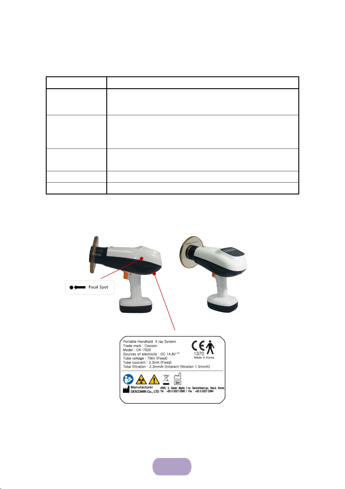
1.4.4 Each part name of main body ........................................................................................................................... 14
1.4.5 DC adaptor & cord ................................................................................................................................................ 15
1.4.6 Battery charging cradle ........................................................................................................................................ 16
1.4.7 External Battery ........................................................................................................................................................ 16
1.5 CHARGING THE BATTERY .................................................................................................................................. 17
2 SAFETY PRECAUTIONS ..................................................................................................19
2.1 RADIATION SAFETY ............................................................................................................................................ 19
SYMBOLS AND DETAILS ..................................................................................................................................................... 19
2.2 CLEANING ............................................................................................................................................................ 21
2.3 SECURITY, STORAGE, AND TRANSPORTATION .............................................................................................. 22
2.3.1 Storage ........................................................................................................................................................................ 22
2.3.2 Check for Product storage .................................................................................................................................. 22
2.3.3 Transportation and Storage conditions ......................................................................................................... 23
3 WARNING / CAUTION AND INSTRUCTIONS ...........................................................23
3.1 WARNING AND INSTRUCTIONS ....................................................................................................................... 23
3.1.1 Warning for product use ..................................................................................................................................... 23
3.1.2 Warnings for Product inspection...................................................................................................................... 23
3.2 CAUTION AND INSTRUCTIONS ......................................................................................................................... 24
3.2.1 Caution for product use ....................................................................................................................................... 24
3.2.2 Caution for storage ................................................................................................................................................ 24

5
3.2.3 Caution for other matters ................................................................................................................................... 24
4 ITEMS TO CHECK ............................................................................................................25
4.1 ITEMS TO CHECK ................................................................................................................................................ 25
5 SETUP AND CHECK ........................................................................................................26
5.1 THE BACK SCATTER SHIELD .............................................................................................................................. 26
5.1.1 Performance of back scatter shield ................................................................................................................. 26
5.2 DETACHABLE BATTERY ....................................................................................................................................... 27
5.3 EXTERNAL BATTERY ........................................................................................................................................... 27
5.4 CHECKING FOR POWER AND BATTERY CHARGE STATE .............................................................................. 28
5.5 BASIC FUNCTION CHECKS ................................................................................................................................ 28
6 OPERATION ......................................................................................................................29
6.1 POWERING UP .................................................................................................................................................... 29
6.2 CHECKING THE BATTERY CHARGE ................................................................................................................... 30
6.3 POWERING OFF .................................................................................................................................................. 31
6.4 EXPOSURE TECHNIQUES ................................................................................................................................... 31
6.4.1 Patient's positioning .............................................................................................................................................. 31
6.4.2 Film or intraoral sensor positioning ................................................................................................................ 31
6.4.3 COCOON positioning ............................................................................................................................................ 32
6.5 CONTROL OF COCOON ................................................................................................................................. 33
6.5.1 Main control screen composition .................................................................................................................... 33
6.5.2 Main control screen ............................................................................................................................................... 33
6.5.3 Setting the Exposure Time .................................................................................................................................. 35
6.5.4 X-RAY exposure ....................................................................................................................................................... 35
6.5.5 X-RAY parameter set ............................................................................................................................................. 37
6.5.6 Screen setting ........................................................................................................................................................... 38
7 QUICK USER GUIDE ........................................................................................................40
8 HOW TO REPLACE THE PRODUCT HANDLE .............................................................43
9 INSPECTION ITEMS BEFORE REPAIR REQUEST ........................................................45
9.1 CHECK ITEMS BEFORE REQUESTING INSPECTION .......................................................................................... 45
9.2 TROUBLESHOOTING ........................................................................................................................................... 46

6
9.3 MAINTENANCE SCHEDULE ................................................................................................................................ 47
9.3.1 On-going check ....................................................................................................................................................... 47
9.3.2 Annual User Check ................................................................................................................................................. 48
9.3.3 Annual Calibration .................................................................................................................................................. 49
9.3.4 Maintenance Log Sheet ........................................................................................................................................ 50
10 TECHNICAL DESCRIPTION AND PRODUCT WARRANTY .......................................51
10.1 BASIC TECHNICAL SPECIFICATIONS ................................................................................................................. 51
10.2 HIGH VOLTAGE GENERATOR ............................................................................................................................ 52
10.2.1 X-ray Tube Specifications and Characteristics ............................................................................................ 52
10.3 EMC DATA ......................................................................................................................................................... 54
10.3.1 Electromagnetic interference ............................................................................................................................. 55
10.4 PRODUCT WARRANTY ...................................................................................................................................... 57

7
1 Getting Started
1.1 Intended Use/ Prohibition of use
COCOON is intended for use only by trained and qualified dentists or dental
technician for both adult and pediatric subjects.
The device is designed for taking diagnostic intraoral dental X-rays using conventional
film or digital sensors.
The device is intended used in hospital/ clinic environment.
Contraindication: COCOON is prohibited for use on patients who known to be or
possibly pregnant.
1.2 Unpack and Check COCOON
1.2.1 Product composition
COCOON consists of item below.
Main body: 1EA
Charging cradle: 1EA
Charger & AC Cord: 1SET
Neck strap (Optional): 1EA
Back Scatter shield (Optional): 1EA
Product bag : 1EA
External Battery (Optional) : 1EA
User Manual(include product warranty certificate): 1EA

8
* Components may change depending on the situation without notice *.
Figure1.1 Product Composition

9
1.2.2 Preliminary Checks
Item Check
Device Labels As shown in Figure 1.2 below, make sure that the label is
attached to the device in place.
Other Labels Make sure that the serial number on the Warranty matches the
device serial number and the device carrying case serial
number.
Collimator cone Inspect for damage. The lead lining must cover the entire
interior surface.
Trigger switch Should move freely in and out when it is pushed and released.
Control panel Should be smooth and free of scratches, damage or nicks
Label-Outside
Figure 1.2 labeling on Main Body

10
Inside: X-ray tube assembly
Figure 1.3 Labeling on X-ray tube assembly
Figure 1.4 Charging Cradle and Adapter

11
1.3 Product Features
1.3.1 Features
Medical Device Name: Portable Handheld X-RAY System
Product Name: COCOON
Model Name: DX-7020
Display: 3.12” OLED (Resolution: 256 x 64)
Function for user
- Exposure time setup in accordance with adult and child or type of the teeth
- Intuitive Graphic User Interface
- Radiation Exposure Interval Setting Function
- Trigger use
- Automatic Shut Down
Designed for user's wrist protection
COCOON LEFT COCOON BACK
COCOON TOP COCOON FRONT
Figure1.5 COCOON drawing

12
1.4 Product specifications
1.4.1 Device main body
COCOON
Main Body
Model Name DX-7020
X-RAY tube focal spot size 0.4 mm
Protection type
B type
Grade for electrical shock
Waterproof rating IPX0
Mode of operation Discontinuous operation
Cooling method Oil cooling method
Total filtration More than 2.3mmAl (inherent filtration: 1.0 mmAl)
Input power DC 14.8 V
Target Angle 12.5˚
Distance to target Distance between target and Focal Spot > 18 cm (7 inch)
Main body weight 2.3 kg (Exclusion Back scatter shield)
Operating temperature 10 - 40℃
Operating humidity 30-75% RH, non-condensing
Atmosphere pressure
condition of use 700 ~ 1060 hPa
Battery Type Embedded inside of main body removable battery type
kV (fixed) 70kV
mA (fixed) 2.0mA
Power consumption 350 W
Exposure time 0.05~1.0sec
Exposure time setting
interval 0.01 sec

13
1.4.2 Charger specification
Model name: BPL910S16F01
Input: AC 100-240[V], 50/60 [Hz], 0.5 [A]
Output Voltage: DC 16.8 [V]
Output Current: 1.0 [A]
1.4.3 Battery charging cradle
Model name: Cradle
Charging voltage: DC 16.8 [V]
Charging current: 1.0 [A]
Discharging voltage (at the time of battery connection): vary depending on
discharging condition
Discharging current (at the time of battery connection): vary depending on
discharging condition
Size: 270(L) x 132(W) x 195(H)

14
X-ray field
Power On/Off Button
Trigger
Safety lock
Exposure lamp
256 x 64 pixel OLED screen
Neck strap hook ring
X-ray mode control
Handle
1.4.4 Each part name of main body
Each part name of main body is as following.
Figure 1.6 each part name of main body
Back scatter shield
External battery connector

15
1.4.5 DC adaptor & cord
The part name of charger is as shown in Figure 1.6.
Inside: X-ray tube assembly
Output indicator lamp: displays the current output status.
Charging power jack: supplies DC output power from the adapter.
Charging adapter label: lists the model name, input/output conditions, certification, serial
number, and so on.
AC input connector: connects the AC input of the power cord.
AC power cord: connects external AC power.
Figure 1.7 part name of DC adaptor part
(TOP)
AC power cord
(BOTTOM)
Charging
adapter label
AC input connector
Charging power jack
Output indicator lamp

16
Charging terminals
DC input connector
Charge indicating lamp
1.4.6 Battery charging cradle
① The name for each part on charging cradle
Charging terminals: connect output terminal of battery pack to charging terminals of
charging cradle and charge the battery.
Charge indicating lamp: Indicates each status of charging or charge completion by
different colors.(red: charging, green: charge completion)
DC input connector: receives charging power from charging adaptor
1.4.7 External Battery
Output terminal jack: supplies DC output power from the external battery. It's length over
than 14.5 inches.
Battery label: lists the model name, input/output conditions, certification, serial number, and
so on.
Battery state LED: indicates each status of charging or charge completion by different colors
(red: charging, green: charge completion)
Figure 1.8 part name of charging cradle
Output terminal jack
Battery label
Battery state LED
Charge terminal
Figure 1.9 part name of external battery (Optional)

17
③ When charging is finished, battery
charging cradle's and DC adapter's LED
indicator turns on green.
Charge terminal: connect charging power jack of DC adaptor to charge terminal of external
battery. Then the external battery is charged.
1.5
Charging the Battery
NOTE: The battery is tested and fully charged for shipping at the factory. However, battery is to be
fully charged prior to initial use to prevent function damage of battery or discharged to lower level
in case unused stored for long time period such as three (3) months.
Internal Battery
① Connect the AC power cord to the AC socket on the charger.
② Connect the DC output connector to the cradle.
③ Put handle of the main body to the cradle.
④ Connect the AC power cord to a power outlet rated AC 100-240[V], 50-60[HZ].
⑤ Battery charging cradle's and DC adapter's LED indicator turns on the red when
power is connected.
⑥ When charging is finished, Battery charging cradle's and DC adapter's LED indicator
turns on the green.
② Connect the DC output connector to the cradle
then put handle of the main body to the cradle.
Figure 1.10 charging the battery
① Connect the AC power cord to
the charger.

18
③ When charging is finished, External
battery and DC adapter LED indicator turns
on green.
External battery
○
1 Connect the AC power cord to the AC socket on the DC adapter
○
2 Connect the DC output connector to the External battery
③ Connect the AC power cord to a power outlet rated AC 100-240[V], 50-60[HZ]
④ External battery and DC adapter LED indicator turns on the red when power is
connected
⑤ When charging is finished, External battery and DC adapter LED indicator turns on
the green
① Connect the AC power cord to
the DC adapter.
② Connect the DC output connector to
the external battery. When power is
connected DC adapter and External
battery LED indicator turns on red.
Figure 1.11 Charging the External battery
Caution
Use only Dexcowin's adapter and cord originally packaged with the device to
prevent damage to battery or accident.
Otherwise, the warranty will be avoided or product liability by a manufacturer
will be exempted.

19
2 Safety Precautions
2.1 Radiation Safety
COCOON complies with MDD 93/42/EEC as amended by 2007/47/EC, IEC60601-1-3,
IEC60601-2-28, IEC60601-2-65, which these are regulations on radiation safety and
protection.
X-RAY operator must pay attention on the status of a patient in case of emergency.
X-RAY operator must stop operating if disorder is detected.
A pregnant or expect to become pregnant woman and child must be advised prior
to X-RAY operation.
Diagnostic Reference Level
Following are comparisons of effective radiation dose with background radiation
exposure for several radiological procedures.
Symbols and details
"Warning" sign explains details of possible user damage, death or physical
damage.
“Warning” means potential danger, in order to avoid serious personal injury
or death.
WARNING
This X-ray unit could be dangerous to the patients or the operators unless
safe exposure factors, operating instructions and maintenance schedule are
observed.
Other manuals for COCOON DX-7020
1
Table of contents
Other Dexcowin Medical Equipment manuals
Popular Medical Equipment manuals by other brands

COOK Medical
COOK Medical Evolution Shortie RL Instructions for use

Van Der Stahl
Van Der Stahl MD-850 Series operating instructions

Landi
Landi LIS Installation and adjustment manual

Fresenius Vial
Fresenius Vial INJECTOMAT 2000 Anasthesie Technical manual

medi
medi M.4 s OA manual

Enovate Medical
Enovate Medical Envoy manual

Covidien
Covidien Valleylab LS10 user guide

TRONITEK
TRONITEK DENAS Reflexo Operation manual

Stryker
Stryker 1231 Operation manual

Agilent Technologies
Agilent Technologies PageWriter 10 Quick reference guide

Invacare
Invacare Perfecto2 IRC5PO2AW Service manual

Aspire
Aspire Community & Homecare Bed Range user manual