manuals.online logo
Brands
  1. Home
  2. •
  3. Brands
  4. •
  5. Dexter Laundry
  6. •
  7. Washer
  8. •
  9. Dexter Laundry N-Series User manual

Dexter Laundry N-Series User manual

USE THE BLUE TABS LOCATED ON THE
RIGHT AND LEFT SIDES OF THE FOLLOWING
DOCUMENT TO ADVANCE TO EACH SECTION.
8533-031-001 6/22
N-Series On-Premise Washer
WCN55AEH
Non-Express
8533-031-001 6/22
Indicates an imminently hazardous situation, which if
not avoided, will result in death or serious injury.
Indicates a potentially hazardous situation, which if not
avoided could result in death or serious injury.
Indicates a potentially hazardous situation which, if not
avoided, may result in minor or moderate injury. It may
also be used to alert against unsafe practices. Minor
burns, pinch points that result in bruises and minor
chemical irritation.
Indicates information or a company policy that relates
directly or indirectly to the safety of personnel or protec-
tion of property.
This is the user caution symbol. It indicates a condition
where damage to the equipment resulting in injury to
the operator could occur if operational procedures are
not followed. TO REDUCE THE RISK OF DAMAGE OR
INJURY, refer to accompanying documents; follow all
steps or procedures as instructed.
This is the electrical hazard symbol. It indicates that
there are DANGEROUS HIGH VOLTAGES PRESENT inside
the enclosure of this product. TO REDUCE THE RISK OF
FIRE OR ELECTRIC SHOCK, do not attempt to open the
enclosure or gain access to areas where you are not
instructed to do so. REFER SERVICING TO QUALIFIED
SERVICE PERSONEL ONLY
Caution! There are sharp edges on various sheet metal
parts internal to the enclosure. Use safety consciousness
when placing or moving your hands while working in the
interior of this equipment.
Caution! To reduce the risk of damage to the Water Inlet
Valve, do not supply inlet water with a temperature that
exceeds 70˚ C.
Caution! To reduce the risk of re or explosion, do not
operate this equipment in any hazardous classied
(ATEX) environment.
Equipment Safety Warnings
Symbols and Terminology Used in this Equipment
3
Part # 8533-031-001 6/22
Machine
Mounting
Installation
& Operation
Trouble-
shooting
Machine
Service
Electrical
Wiring
Parts
Data
Coin
Handling
Maintenance
Warning! Do not operate equipment if door glass is
damaged in any way.
Warning! Keep clear of rotating parts.
Prohibited! Do not enter this equipment or space.
Prohibited! Do not step or stand on this equipment.
Prohibited! Do not operate without all guards and covers in
place.
Prohibited! Do not operate without all guards and covers in
place.
Prohibited! Do not wash clothing impregnated with
ammable liquids (petrochemical).
Prohibited! Do not allow children to play in or around
equipment.
Equipment Safety Warnings
Symbols and Terminology Used in this Equipment Indicates an imminently hazardous situation,
which if not avoided, will result in death or seri-
ous injury.
Indicates a potentially hazardous situation,
which if not avoided could result in death or
serious injury.
Indicates a potentially hazardous situation
which, if not avoided, may result in minor or
moderate injury. It may also be used to alert
against unsafe practices. Minor burns, pinch
points that result in bruises and minor chemical
irritation.
Indicates information or a company policy that
relates directly or indirectly to the safety of per-
sonnel or protection of property.
This is the user caution symbol. It indicates a
condition where damage to the equipment re-
sulting in injury to the operator could occur if
operational procedures are not followed.
TO REDUCE THE RISK OF DAMAGE OR INJURY,
refer to accompanying documents; follow all
steps or procedures as instructed.
This is the electrical hazard symbol. It indicates
that there are DANGEROUS HIGH VOLTAGES
PRESENT inside the enclosure of this product.
TO REDUCE THE RISK OF FIRE OR ELECTRIC
SHOCK, do not attempt to open the enclosure or
gain access to areas where you are not instruct-
ed to do so. REFER SERVICING TO QUALIFIED
SERVICE PERSONEL ONLY
Caution! To reduce the risk of re or explosion,
do not operate this equipment in any hazardous
classied (ATEX) environment.
4 5
Part # 8533-031-001 6/22 Part # 8533-031-001 6/22
Machine
Mounting
Installation
& Operation
Trouble-
shooting
Machine
Service
Electrical
Wiring
Parts
Data
Coin
Handling
Maintenance
• All washers must be installed in accordance to
all applicable electrical, plumbing and all other local
codes.
• These installation and operation instructions are
for use by qualied personnel only. To avoid injury
and electrical shock, do not perform any servicing
other than that contained in the installation and op-
eration instructions, unless qualied.
Do not install washers in an explosive atmosphere.
•Care must be stressed with all foundation work to
ensure a stable unit installation, eliminating pos-
sibilities of excessive vibration.
•Foundation must be level within 13 mm to ensure
proper washer operation.
Do not operate washer if door glass is damaged in
any way.
Do not wash clothing impregnated with ammable
liquids (petrochemical).
WARNING
Children should be supervised to
ensure they do not operate or play
in or around equipment.
Keep all panels in place to protect against electrical
shock and injury and add rigidity to washer.
WARNING
This appliance is not intended for use by persons (including
children) with reduced physical, sensory or mental capabilities, or
lack of experience and knowledge, unless they have been given
supervision or instruction concerning use of the appliance by a
person responsible for their safety.
A washer should not be allowed to operate if any of the following occur:
• Excessive high water level.
• Machine is not connected to a properly earthed circuit.
• Door does not remain securely locked during the entire cycle.
• Vibration or shaking from an inadequate mounting or foundation
6 7
Part # 8533-031-001 6/22 Part # 8533-031-001 6/22
Machine
Mounting
Installation
& Operation
Trouble-
shooting
Machine
Service
Electrical
Wiring
Parts
Data
Coin
Handling
Maintenance
Warning! Do not operate equipment if door glass is
damaged in any way.
Warning! Keep clear of rotating parts.
Prohibited! Do not enter this equipment or space.
Prohibited! Do not step or stand on this equip-
ment.
Prohibited! Do not operate without all guards and
covers in place.
Prohibited! Do not operate without all guards and
covers in place.
Prohibited! Do not wash clothing impregnated
with ammable liquids (petrochemical).
Prohibited! Do not allow children to play in or
around equipment.
Prohibited! Do not attempt to open, touch, or pro-
ceed before referring to the manual or unless quali-
ed.
Mandatory! Read all supporting documentation be-
fore operating or maintaining equipment.
Mandatory! Disconnect power before servicing
equipment.
Mandatory! Lock out and tag out before servicing
this equipment.
Mandatory! Disconnect water supply before servic-
ing equipment.
Mandatory! Children should be supervised to ensure
they do not operate equipment.
8 9
Part # 8533-031-001 6/22 Part # 8533-031-001 6/22
Machine
Mounting
Installation
& Operation
Trouble-
shooting
Machine
Service
Electrical
Wiring
Parts
Data
Coin
Handling
Maintenance
A machine should not be allowed to
operated if any of the following occur:
• Excessively high water level.
• Machine is not connected to a properly grounded
circuit.
• Loading door does not remain securely locked
during the entire cycle.
• Vibration or shaking from an inadequate mounting
or foundation.
Table of Contents
Section 1: Machine Mounting &
Installation......................................Pg 14
Section 2: Machine Installation &
Operating Instructions............Pg 23
Section 3: Electrical Wiring.....Pg 31
Section 4: Machine Service
Procedures...............................Pg 40
Section 5: Troubleshooting......Pg 56
Section 6: Parts Data..............Pg 64
Section 7: Coin Handling.......Pg 103
Section 8: Maintenance........Pg 106
Dexter Safety
Guidelines
FOR SAFETY
1. Always shut o power and water
supply and also discharge capacitors
before servicing.
2. Do not overload the washer.
3. Do not attempt to open door if cylinder
is in motion or contains water.
4. Do not mechanically force or override
door lock in any way.
5. Do not bypass any safety devices of
this washer.
6. Do not use volatile or ammable
substances in or near this washer.
7. Keep all panels in place. They protect
against shock and injury and add
rigidity to the washer.
To activate your warranty, be sure to return
your red warranty form to the factory. Please
have serial number and model ready when
calling for assistance.
WARNING
These washers are equipped with devices and
features relating to their safe operation. To
avoid injury or electrical shock, do not perform
and service, unless qualied to do so.
10 11
Part # 8533-031-001 6/22 Part # 8533-031-001 6/22
Notes
Machine
Mounting
Installation
& Operation
Trouble-
shooting
Machine
Service
Electrical
Wiring
Parts
Data
Coin
Handling
Maintenance
12 13
Part # 8533-031-001 6/22 Part # 8533-031-001 6/22
Notes Notes
Machine
Mounting
Installation
& Operation
Trouble-
shooting
Machine
Service
Electrical
Wiring
Parts
Data
Coin
Handling
Maintenance
Specications for below model
is outlined in this book:
WCN55AEH 208-240 volts 60hz. Single Phase/Three Phase
Cycle
Times
Rotary Switch
Position #1
Rotary Switch
Position #2
Rotary Switch
Position #3
Rotary Switch
Position #4
Chemical
Signal
Water Level
Flush 3 minutes 3 minutes Not Used Not Used No High
Drain 42 seconds 42 seconds Not Used Not Used
Preswash 3 minutes 3 minutes 3 minutes 3 minutes Yes -- A High
Drain 42 seconds 42 seconds 42 seconds 42 seconds
Wash 7 minutes 7 minutes 7 minutes 7 minutes Yes -- B Low
Drain 49 seconds 49 seconds 49 seconds 49 seconds
Rinse 1 2 minutes Not Used 2 minutes 2 minutes No High
Drain 41 seconds Not Used 41 seconds 41 seconds
Rinse 2 7 minutes 7 minutes 7 minutes Not Used Yes -- C Low
Drain 49 seconds 49 seconds 49 seconds Not Used
Rinse 3 2 minutes 2 minutes 2 minutes 2 minutes No High
Drain 41 seconds 41 seconds 41 seconds 41 seconds
Int. Spin 2 minutes 2 minutes 2 minutes 2 minutes
Rinse 4 2 minutes 2 minutes 2 minutes 2 minutes No High
Drain 41 seconds 41 seconds 41 seconds 41 seconds
Rinse 5 4 minutes 4 minutes 4 minutes 4 minutes Yes -- D Low
Drain 41 seconds 41 seconds 41 seconds 41 seconds
Extract 5 minutes 4 minutes 5 minutes 3.5 minutes
Tumble 37 seconds 37 seconds 37 seconds 37 seconds
Tot al* 43 minutes 39.5 minutes 39.5 minutes 30.5 minutes
*Cycle times are approximate and do not include ll time from empty to low level. Fill time from
low to high level is included as timer operates during this period.
Water Temp Push-Button Temp
Switch #1
Push-Button
Temp Switch #2
Push-Button Temp
Switch #3
Push-Button
Temp Switch #4
Flush Warm Warm Warm Cold
Preswash Warm Warm Warm Cold
Wash Hot Warm Warm Cold
Rinse 1 Hot Hot Warm (Hot OPT) Cold
Rinse 2 Hot Hot Warm (Hot OPT) Cold
Rinse 3 Warm Warm Warm (Cold OPT) Cold
Rinse 4 Warm Warm Warm (Cold OPT) Cold
Rinse 5 Warm Warm Warm (Cold OPT) Cold
Options
1. Replace all Hot rinses with Warm rinses by removing brn/red wire from coil of R5 relay and insulate.
2. Push button #3 replace Warm rinse 1 & 2 with Hot by removing black jumper wire between push but-
ton #3 and push button #4 and connecting the white/brn wire (piggybacked on the black jumper) to push
button #4 normally openterminal B1
3. Replace Warm rinse 3,4, &5 on push button #3 by moving brn/org wire from push button #3 common
terminal A2 to push button #3 normally closed terminal C2.
15
Part # 8533-031-001 6/22
14
Part # 8533-031-001 6/22
Section 1:
Machine
Mounting
Machine
Mounting
Installation
& Operation
Trouble-
shooting
Machine
Service
Electrical
Wiring
Parts
Data
Coin
Handling
Maintenance
Specications
T-900 Coin Washer
Capacity 55lbs.
Dimensions
Cylinder Depth 22”
Cylinder Diameter 30”
Cylinder Volume (cubic feet) 9.0
Door Opening 15 1/4”
Door Height (oor to bottom of
door)
18 3/8”
Overall Height 54”
Cabinet Width 34 3/8”
Overall Depth 38 3/4”
Drain Diameter (O.D.) 3”
Drain Height (oor to center of
outlet)
7 1/2”
Recommended Clearance Be-
tween Machines (min)
1/2”
Necessary Service Clearance
Behind Machine
24”
Cylinder RPM
Tumble Speed 43
Extract Speed 531
Extract Speed G-Force 120
Cylinder Direction in Extract Counter-clockwise
Motor H.P.
Wash Single Phase 3
Wash Three Phase 3
Extract Single Phase 3
Extract Three Phase 3
Amperage (avg. measured on L1)
Wash Single Phase 3
Wash Three Phase 3
Extract Single Phase 4.2
Extract Three Phase 4.2
Running Amps (Maximum)
Single Phase 8.4
Three Phase 8.4
Circuit Breaker (Amps)
Single Phase 15
Three Phase 15
Built-in Controls Circuit Breaker Yes
Built in Motor Protection Yes
Voltage 60Hz.
Single Phase 220-240
Three Phase 208-240
Service
Single Phase 2 wires + ground
Three Phase 3 wires + ground
Wire Size (Minimum)
Single Phase 12
Three Phase 12
Water
Recommended Hot Water
(degrees)
140
Water Pressure (min/max) 30-120psi
Water Inlet Size (hose
thread)
3/4”
Water Flow Rate (gallons/
minute)
9
Wash Cycle
Wash Temperatures Hot, Warm, &
Cold
Rinse Temperatures Cold-Std;
Warm-Opt
Mounting Hole Dimensions
Left to Right 27 3/4”
Front to Cabinet to First
Hole
2 3/4”
First Hole to Second Hole 23”
Second Hole to Third Hole 11”
Mounting Bolt Diameter 3/4”
Hole Diameter in Base 1”
Concrete Thickness (min) 8”
Recommended Mounting
Height
4” to 10”
Weight
Shipping (lbs.) 1075
Net (lbs.) 1025
Wash Formulas
Application Formula Mechanical
Timer
Rotary Switch
Position
Shirt Laundry
oxygen bleach
Shirts (No Starch)
Shirts (Starch)
X
X
4 (A)
4 (A)
Hotel/Motel
chlorine bleach
White sheets
White pillowcases
White towels, bath mats, & washclothes
Colored sheets & towels
Delicate Wash
Housekeeping rags & mops
Houskeeping Uniforms
Stain Treatment
Reclaim Part 1
Reclaim Part 2
X
X
X
X
X
X
X
No
No
No
2 (B)
1 (B)
3 (B) or 1 (B)
4 (B) or 1 (B)
4 (B)
1 (C)
2 (D)
Healthcare
chlorine bleach
Sheets & Pillowcases
Towels
Diapers & Pads
Personals
Delicates
X
X
X
X
X
2
3 or 1
1 (K)
4
4
Food & Beverage
chlorine bleach
White (Cotton/Blend) Table Linen
Colored (Cotton/Blend) Table Linen
White (100% Polyester) Table Linen
Colored (100% Polyester) Table Linen
White Chef Coats
Kitchen & Maintenance Rags
X
X
X
X
X
X
3 (E)
2 (F)
3 (E)
2 (F)
1 (J)
1 (G)
oxygen bleach White/Colored (Cotton/Blend) Table Linen
White/Colored (100% Polyester) Table Linen
White Chef Coats
Kitchen & Maintenance Rags
X
X
X
X
3 (H)
3 (H)
1 (G)
1 (G)
Other
oxygen bleach
Oxygen Bleach Terry
Oxygen Bleach Terry (No Iron)
Open
X
X
No
1 (G) or 3 (L)
1 (G) or 3 (L)
(A) Switch Position #4 gives 7 minute wash. Flush & Prewash eliminated with jumper (connect
orange/white wire to terminal strip #2).
(B) Flush & Prewash eliminated with jumper (connect orange/white wire to terminal strip #2).
(C) Switch Position #1 gives 2 ushes/3 rinses after bleach
(D) Switch Position #2 gives either 2 ushes or 0 ushes. Flush & Prewash eliminated with
jumper (connect orange/white wire to terminal strip #2).
(E) Switch Position #3 gives 7 minute wash.
(F) Switch Position #2 gives either 2 or 0 ushes with a 7 minute wash. Flush & Prewash
elimiated with jumper (connect orange/white wire to terminal strip #2).
(G) Switch Position #1 gives 3 minutes ush/3 min. prewash/7 min. wash/5 rinses
(H) Switch Position #3 gives 7 minute wash/7 minute 2nd rinse
(J) Switch Position #1 gives 3 minute ush/3 min. prewash/7 min. wash
(K) Switch Position #1 gives 2 ushes
(L) Same as (G) only deletes rst ush
Please refer to OPL Washer CYCLE TIMES charts for all available options.
16 17
Part # 8533-031-001 6/22 Part # 8533-031-001 6/22
Machine
Mounting
Installation
& Operation
Trouble-
shooting
Machine
Service
Electrical
Wiring
Parts
Data
Coin
Handling
Maintenance
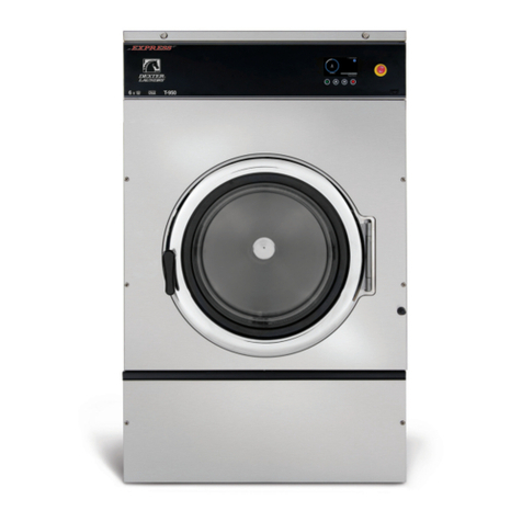
T-900 Mounting Pad Dimensions
18 19
Part # 8533-031-001 6/22 Part # 8533-031-001 6/22
Machine
Mounting
Installation
& Operation
Trouble-
shooting
Machine
Service
Electrical
Wiring
Parts
Data
Coin
Handling
Maintenance
Installation & Operation
All washers must be installed in accordance with all local, state and national building,
electrical, and plumbing codes in eect in the area.
Foundation Requirements
The washer must be securely bolted to a substantial concrete oor or mounted upon a suitable base
which is in turn securely bolted to a substantial concrete oor. Care must be stressed with all foundation
work to ensure a stable unit, eliminating vibration. All installations must be made on sound concrete oors
8” or thicker.
Mounting
A concrete pad or steel base which elevates the machine 4 inches above the oor level is recommended
to provide easy access to the loading door. Allow a minimum of 24” of clearance behind the rear of the
machine for service as is shown. Six bolts are required to mount the washer to the steel base or concrete
pad.
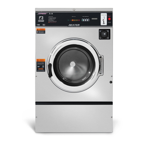
Mounting Holes
The following pages illustrate the mounting dimensions for the machine and also show a typical concrete
pad arrangement. Note: Mounting bolts should be checked frequently to ensure that they remain tight.
The machine should be checked with a spinning load to be sure there is no unusual vibration or movement
between the machine and the base or oor.
Plumbing
Water supply hoses are furnished with each machine. The threaded connections on the hoses are
standard garden hose type thread. Separate hot and cold water lines with shut o valves or faucets for
inlet hose connections must be provided, maintaining 30 to 120 psi. water ow pressure. A hot water
recovery rate of approximately 70 gallons per hour is required with normal wash and cold rinses. A hot
water temperature of 140 degrees Fahrenheit is recommended for best washing results.
Drain
The drain outlet tube at the rear of the machine is 3” in outside diameter. A exible hose (Pt. No. 9242-
417-003) is available to extend the drain system. Adequate fall must be maintained for proper drainage.
Protective Film
The machine may have protective adhesive lm on the front escutcheon area and the front and side
stainless steel panels. The lm may be peeled o before putting the machine into service.
Electrical
Dexter WCN55 series washers are intended to be permanently installed appliances. The machines should
be connected to an individual branch circuit not shared by lighting or other equipment. The electrical
connection should be sheathed in water proof exible conduit, or equivalent, with conductors of the
proper size and insulation (suggested size below). A power cord is not provided. The following diagram
shows the proper power connections to the rear terminal block for both 1 and 3 phase machines. Wiring
should be performed by a qualied person.
Electrical power connections are made to the terminal block located at the upper right-rear corner of the
washer (viewed from the front). The terminal block is accessed by removing the cover.
21
Part # 8533-031-001 6/22
20
Part # 8533-031-001 6/22
Section 2:
Machine
Installation
& Operating
Instructions
Machine
Mounting
Installation
& Operation
Trouble-
shooting
Machine
Service
Electrical
Wiring
Parts
Data
Coin
Handling
Maintenance
1 Phase 3 Phase
220-240 volts, 60 Hz. 208-240 volts, 60 Hz.
3 wire plus ground 3 wire plus ground
(high leg must go on L3)
Suggested Minimum Wire Size --12 Ga.
Fusing Requirements
Dual element time delay fuse or equivalent breaker of amperage specied below.
1 Phase/3 Phase 15 amp When injection pump takes only signal pulses from washer
terminal block.
1 Phase/3 Phase 20 amp When injection pump uses washer terminal block for its power
supply as well as signal pulses.
Always disconnect electrical power to the machine before performing any adjustments or service work.
Liquid Chemical Connection
In the left rear corner of the washer is the chemical injection assembly. This is where all chemical hose
connections are made. The chemical hoses should be inserted into the round PVC pipe of 14” and a
maximum of 18” to eliminate the chemical buildup in the pipe and/or restrict water ow to the tub.
Final Check Out
After all mounting, plumbing, and electrical work is completed, the washer should be run through a cycle
and checked for water leaks and proper functioning.
WARNING
Always disconnect electrical power to the
machine before performing any adjustments
or service.
Cycle Options
Omit All Flushes
1. Remove the cler in-line splice from the end of the orange/white wire. (This wire will
be laying loose next to the terminal strip)
2. Connect the orange/white wire to terminal #2 on the terminal strip.
Omit Hot Rinses on Rinse #1 & #2
1. Remove brown/red wire from coil of R5 relay and insulate wire.
Add Hot Rinses on Rinse #1 & Rinse #2 on Temperature Push Button
Position #3
1. Remove black jumper from back of temperature switch that connects push button
#3 N.O. (B2) to push button #4 N.O. (B1)
2. Move white/brown wire on back of temperature switch to push button #4 N.O. (B1)
Add Cold Rinses on Rinse #3, #4, & #5 on Temperature Push Button
Position #3
1. Move brown/orange wire from push button #3 Common (A2) to push button #3 N.C.
(C2).
Omit Rinse #4 All Cycles
1. Remove the clear in-line splice from the end of the gray wire. (This wire will be
laying loose next to the terminal strip)
2. Connect the gray wire to terminal #2 on the terminal strip.
22 23
Part # 8533-031-001 6/22 Part # 8533-031-001 6/22
Machine
Mounting
Installation
& Operation
Trouble-
shooting
Machine
Service
Electrical
Wiring
Parts
Data
Coin
Handling
Maintenance
Operating Instructions
Starting the Washer
A. Load the clothes in the cylinder and latch the door.
Check to insure that clothes do not get caught
between the door gasket and the tub front.
B. Make the appropriate cycle selection for the wash
load using the 4-position rotary selector switch.
C. Make the appropriate temperature selection for the
wash load using the 4-push button temperature
selector switch.
D. To manually add wash compounds, pour low-
sudsing powdered detergent in the amount shown
below into the detergent dispenser on top of the
machine. Rinse conditioners may also be added
to the dispenser. The correct location is shown on
the dispenser lid.
E. To manually add bleach in Rinse, pour bleach in
round opening (location shown on dispenser lid) in
top of washer.
F. To start the washer:
1. The top (O/On) and bottom (Pause/Run)
rocker switches must be in the right hand
position.
2. The center (Advance/Start) rocker switch
must then be pushed to the right hand
position to begin the cycle.
G. To rapid advance the washer during a cycle, push
the center (Advance/Start) rocker switch to the left
hand position.
H. To pause for an extended soak, push the bottom (Pause/Run) rocker switch to the left hand
position.
I. To stop the wash cycle and drain the water, push the top (On/O) button to the left hand
position.
Safety Door Lock
If power is interrupted the Safety Door Lock delays opening the door until it is safe to do so. If power
failure occurs or if power is interrupted during maintenance, it will be necessary to wait 2 to 3 minutes
before the door can be opened.
End of Cycle
When the cycle is completed, the washer will stop, the on light will go o, and the loading door will
unlock. It can be opened by turning the door handle to the indicated position and pulling. Leave the
clothes door open when the machine is not in use.
Detergent Measurements
By Washer Model
Maxi Load T-900 Washer
25
24 25
Part # 8533-031-001 6/22 Part # 8533-031-001 6/22
Notes
Machine
Mounting
Installation
& Operation
Trouble-
shooting
Machine
Service
Electrical
Wiring
Parts
Data
Coin
Handling
Maintenance
Electrical Path Circuit Schematics
Timer Sequence Chart
The timer sequence charts are used in conjuction with the wiring diagrams to trace the circuitry during the
time cycle. The timer contacts and the operation or component that each contact controls are listed down
the left side of the chart. The phases of the complete cycle are shown across the bottom of the chart. The
timer switch increments are numbered across the top of the chart. The solid horizontal bars in the chart
denote when the various contacts are closed during the cycle.
To use the timer sequence chart to trace the circuitry:
1. Locate the particular part of the cycle on the sequence chart.
2. Determine which timer contacts are closed during that particular step of the cycle by noting the solid
vertical bars in that step across the chart.
3. Draw in the gap of the respective contacts on the wiring diagram with a soft dark pencil, to illustrate
the contacts are being closed.
4. Similarly, determine which switch contacts are closed, by the switch chart, and illustrate them as closed
on the wiring schematic.
5. The circuitry during the particular step of the cycle may then be easily traced on the wiring diagram,
since all contacts and switches are then properly illustrated as being open or closed.
Start Circuit
Power travels into the control trough on L1 &L2. 240VAC goes to a Control Transformer that steps the volt-
age down to 120VAC for the controls. 120VAC then travels thru the 1.5 amp Circuit Breaker and travels on
the white/red wire to the Coin Accumulator Transformer where it is stepped down to 12VAC. This 12VAC
powers the Coin Accumulator Board via the gray wire. With the board now powered up, the insert coins
light will be illuminated and it’s ready to count coins.
120VAC is also supplied to the Main Timer Start and On-O Contacts on the white/red wire. The Start
Contact is closed before the machine has been started so 120VAC travels through the Start Contact and is
sup plied to the Coin Accumulator Board Start Relay. The S4 Coin Switch counts the quarters and sends a
signal to the Coin Accumulator Board. When the coin count is satised, the Coin Accumulator Board closes
the Start Relay and sends a short 120VAC signal on the orange/white wire to the Rapid Advance Timer
Motor. This timer motor starts advancing the Main Timer to the preselected starting position. A few sec-
onds after the Coin Accumulator Board sends the start signal to the Rapid Advance Timer Motor, the Coin
Accumulator Start Relay opens, the display goes blank and the On-O Contact in the Main Timer closes to
ensure that the S1 Door Switch is closed (showing that the door is locked). The On-O Contact also pro
vides 120VAC to the On Light on the red wire. With the S1 Switch closed the Door Lock Solenoid is now
powered with 120VAC via the white/red wire. The Door Lock Solenoid pulls in, locking the door and closing
the S2 and S3 Switches. The S2 Switch is a backup to the S1 Switch so that the adjustment on S1 isn’t as
critical. The S3 Switch provides 120VAC to Timer Contact RA-3 to power the Rapid Advance Motor again
and the Main Timer is allowed to advance on to the preselected start position. The blue wire furnishes the
neutral for the controls.
Fill Circuit-Warm
120VAC is supplied to the controls through the S1, S2, and S3 Door Switches. The On Light and the Door
Lock Solenoid (discussed in Start Circuit) will remain on throughout the cycle. The Lock Thermoactuator
Contact in the Main Timer is closed and provides the neutral side to operate the Thermoactuator. 120VAC
is provided.to the Lock Thermoactuator on the orange wire from the S3 Door.Switch. The Drain Contact in
the Main Timer is closed and pro vides 120VAC to the Drain Valve on the brown/yellow wire which closes
the valve. The Wash Contact in the Main Timer is closed and provides 120VAC to the Reversing Timer and
the Reversing Timer Motor on the blue/black wire. This will start the Reversing Timer operating which will
alternately open and close the Micro Switches that provide the direction of tumble for the wash basket.
The Wash Light Contact in the Main Timer is closed and provides 120VAC to the Wash Light. The orange
wire coming from the S3 Door Switch provides power to the Wash Water Contact in the Main Timer.
120VAC connects. from the Wash Water Contact to the Wash Temperature Contact via an internal timer
connection. With 120VAC on the orange wire & neutral on the orange/yellow wire, the Coin Accumulator
Board turns on the Time Remaining Light & starts counting down in minutes. (If delay ll kit is installed,
time count down is stopped during ll.)
27
Part # 8533-031-001 6/22
26
Part # 8533-031-001 6/22
Section 3:
Electrical
Wiring Diagrams &
Schematics
Machine
Mounting
Installation
& Operation
Trouble-
shooting
Machine
Service
Electrical
Wiring
Parts
Data
Coin
Handling
Maintenance
Fill Circuit-Warm Continued...
Now a cycle must be selected with the Selector Switch. We’ll use Normal Wash. The washer lls the tub
through the back of the machine with either one or both the C1 Cold and H1 Hot Water Valves. At the
beginning of the cycle, the detergent dispenser ushes the detergent into the tub. This is accomplished
with the Wash Dispenser Contact in the Main Timer. 120VAC travels through the closed Wash dispenser
Contact and is supplied to the H2 Hot Water Valve Solenoid by the red/orange wire. As the washer lls
with water, the Wash Basket will tumble one direction for 19 seconds, pause, and then reverse direc-
tion for 19 seconds. 120VAC travels from the Wash Water Timer Contact to the Heavy Duty Contact in
the Selector Switch via the white/black wire. 120VAC goes through the closed Heavy Duty Contact in the
Selector Switch and energizes the C1 Cold Water Valve Solenoid via the white/orange wire. 120VAC also
travels to the closed Wool/Delicate Contact in the Selector Switch. This closed contact provides power to
the H1 Hot Water Valve Solenoid via the red/yellow wire. When the water reaches the predetermined level
the Pressure Switch moves to the full position and opens the neutral side of the line to the Water Valves.
This shuts the Water Valves o. The neutral for the Water Valves & Main Timer Motor is provided through
the Pressure Switch. The Main Timer is stopped until the Pressure Switch provides neutral when full level
is reached. Neutral for the Main Timer Motor during drain and spin is provided through the Delay Fill Timer
Contact.
120VAC travels from the Wash Water Timer Contact to the Heavy Duty Contact in the Selector Switch via
the white/black wire. 120VAC goes through the closed Heavy Duty Contact in the Selector Switch and
energizes the C1 Cold Water Valve Solenoid via the white/orange wire. 120VAC also travels to the closed
Wool/Delicate Contact in the Selector Switch. This closed contact provides power to the H1 Hot Water
Valve Solenoid via the red/yellow wire. When the water reaches the predetermined level the Pressure
Switch moves to the full position and opens the neutral side of the line to the Water Valves. This shuts the
Water Valves o.
Wash Circuit
As the washer lls the tub through the back of the machine with either one or both the C1 Cold and H1
Hot Water Valves, the Wash Basket will tumble one direction for 19 seconds, pause, and then reverse
direction for 19 seconds. This is accomplished through the use of a Reversing Timer. 120VAC is supplied to
the Reversing Timer Motor on the blue/black wire from the Wash Motor Timer Contact in the Main Timer
and 120VAC is supplied to the R1 Run Relay any time the door is locked. This R1 Relay closes & provides
24VDC thru the Reversing Timer Wash Micro Switches. The Reversing Timer will alternately open and close
the two Wash Micro Switches and provide 24VDC to the FW (forward) or RV (reverse) terminals on the
Variable Frequency Drive.
As discussed in Start and Fill, the Lock Thermoactuator, Drain Valve, On Light, and Main Timer Motor (ex-
cept in ll) are all operating throughout the Wash Cycle.
Drain, Rinse 1 & 2, and Final Rinse Circuit
The Drain Contact on the Main Timer opens. removing power to the Drain Valve. The normally-open
spring-loaded Drain Valve opens and empties the tub.
For Rinse 1 & 2, the Rinse Light Contact in the Main Timer closes and provides 120VAC to the Rinse Light.
The Rinse Water Contact in the Main Timer also closes and provides 120VAC to the C1 Cold Water Sole-
noid. The tub will ll until the predetermined level is achieved at which time the.Pressure Switch Contact
will open the neutral side of the line shutting o the C1 Cold Water Solenoid. When the tub is full, the
pressure switch also closes a neutral circuit to the M1 Timer Motor and to the orange/yellow wire on the
Coin Accumulator Board. This allows the Main Timer to advance only after the tub is full and stalls the time
count down on the Coin Accumulator Board during lls.
For the Final Rinse, the. Final Rinse Light Contact in the Main Timer closes and provides 120VAC to the
Final Rinse Light. Rinse water is the same as in Rinses above.
As discussed in Start and Fill, the Lock Thermoactuator, Drain Valve, On Light, and Main Timer Motor (ex-
cept in ll) are all operating throughout the Wash Cycle.
Intermediate Extract Circuit
The Wash Contact remains closed and provides 24VDC to the closed Clockwise Micro Switch on the
Reversing Timer. 24VDC is then fed to the Counter Clockwise Micro Switch via a jumper wire..120VAC is
then sent to the Delay Spin Micro Switch. The Delay Spin Micro Switch provides 120VAC to the Spin Motor
Contact in the Main Timer on the blue/white wire. The Spin Motor Contact is closed for spin and the volt-
age continues on to the R2 Spin Motor Relay Coil on the red/black wire. With 120VAC to the R2 Spin Motor
Relay Coil two things happen. 120VAC is now provided from the orange wire directly to the Relay eliminat-
ing the Reversing Timer and the Micro Switches from the circuit.
The second thing that happens when the R2 Relay is closed is that 24VDC is provided from the DCM ter-
minal of the Variable Frequency Drive through the R1 Run Relay through the R2 Spin Relay to terminals Ml
1 & Ml3 on the Drive and the washer spins at intermediate speed.
Final Extract Circuit
Same as Intermediate Extract but adds the R3 Extract Relay. The Main Timer provides 120VAC to the
Extract Relay Coil. When this relay closes it provides 24VDC to the Ml2 terminal on the Variable Frequency
Drive. This means that all 3 terminals Ml1, Ml2 & Ml3 are powered for high spin.
Unlock Thermoactuator and Shake Out Circuit
The Lock Thermoactuator Contact in the Main Timer opens 1 1/2 minutes before the end of the cycle
removing the neutral to the Thermoactuator. This allows the Thermoactuator time to retract by the end of
the cycle.
To insure that the Lock Thermoactuator has retracted by the end of the cycle, 1 minute prior to the end
of the cycle, the Unlock Thermoactuator is powered with 120VAC through the Unlock Thermoactuator
Contact in the Main Timer.
The Spin Motor Contact in the Main Timer opens, stopping voltage to the R2 Spin Motor Relay & the mo-
tor. The basket will coast to a stop. The Wash Motor Contact in the Main Timer closes providing power to
the Reversing Timer once again (discussed in Wash Cycle). The washer will tumble for approximately 30
seconds to let the clothes shake loose and then stop.
End of Cycle Circuit
The On-O Contact in the Main Timer opens removing power to the Door Lock Switches and Contactors.
The machine is now stopped. The Start Contact on the Main Timer is closed providing 120VAC to the Coin
Accumulator Board on the white/green wire.
The End Of Cycle Contact in the Main Timer is closed sending a 120VAC signal to the Coin Accumulator
Board on the white/yellow wire telling it that the cycle is over. This does 2 things:
1. The beeper will signal for 3 seconds letting the user know that it is the end of the cycle.
2. It resets the Coin Accumulator Board and it is now ready to count coins again.
28 29
Part # 8533-031-001 6/22 Part # 8533-031-001 6/22
Machine
Mounting
Installation
& Operation
Trouble-
shooting
Machine
Service
Electrical
Wiring
Parts
Data
Coin
Handling
Maintenance
30 31
Part # 8533-031-001 6/22 Part # 8533-031-001 6/22
Machine
Mounting
Installation
& Operation
Trouble-
shooting
Machine
Service
Electrical
Wiring
Parts
Data
Coin
Handling
Maintenance
33
Part # 8533-031-001 6/22
32 Part # 8533-031-001 6/22
Section 4:
Machine Service
Procedures
Top Panel Removal
Step 1: Remove 4 screws that hold detergent dispenser to top panel.
Step 2: Unlock top panel lock.
Step 3: Raise top panel, slide to the rear to release from back clips and lift o.
Front Panel Removal
Step 1: Remove 2 screws between front panel top and front (located behind control panel).
Step 2: Remove the two screws in the middle of the front panel.
Step 3: Pull panel out at the bottom to about a 45 degree angle to detach the top lip and remove.
Back Panel Removal
Step 1: Remove all screws holding back panel in position except the bottom row.
Step 2: The bottom row of screws are slotted and only need to be loosened and to lift o panel.
NOTE: The back panel is not only a safety requirement but also contributes to the rigidity
of the cabinet.
Drain Valve Access
For access, remove lower service panel. The drain valve is a ball type and is powered closed by the drain valve
motor. It is spring loaded open. If power is interrupted to the washer, the motor releases the sealing ball,
allowing the drive spring to open the valve. With the valve open, all water in the washer will drain out.
Chemical Injection Assembly
In the left rear corner of the washer is the chemical injection assembly. This is where all chemical hose
connections are made.
Drain Valve Cleaning
Step 1: Loosen the clamp on the tub hose at the drain valve end and remove the hose from the drain valve.
Step 2: Loosen the drain hose clamp on the back of the drain valve. Remove two drain valve mounting
racket screws from the frame of the washer.
Step 3: Remove the drain valve and bracket assembly.
Step 4: Unplug the wiring after the drain valve is removed from the washer.
Detergent Dispenser
Remove top panel to access dispenser. (see Removing Top Panel)
Detergent is ushed from the front of the compartment and fabric
softener is ushed from the back. There will be a small amount of
water left in the fabric softener compartment after each use.
Vacuum Breaker (also called an air gap)
In the left rear of the cabinet is the vacuum breaker. It guides
the water to the tub and dispenser and prevents a back ow of
water.
Water Valves
Remove top panel to access water valves. (see Removing
Top Panel) The two dual outlet water valves are mounted
to the rear channel with two screws each. Always check
inlet screens to be sure that they are clean. Disassembly
requires the removal of two solenoid screws and three valve
body screws. Below the solenoid coil is a solenoid guide,
armature, armature spring and diaphragm. All valve parts
are available individually or as a complete unit.
Masking Ring (door lock cover) Removal
A. Remove front panel.
B. Remove nuts that retain masking ring.
C. Move it to the left and o.
34 35
Part # 8533-031-001 6/22 Part # 8533-031-001 6/22
Machine
Mounting
Installation
& Operation
Trouble-
shooting
Machine
Service
Electrical
Wiring
Parts
Data
Coin
Handling
Maintenance
Door Lock Assembly Operation
After loading the clothing, the door should be closed and latched. The locking cam on the door contacts
the latching switch actuator which closes the latching switch. The specied number of coins should now
be added to start the washer. The gear motor pulls up on the locking pawl by use of a linkage rod. The
locking pawl has two jobs. The rst is to lock the door. This is accomplished by blocking the locking cam
on the door so that it can’t rotate to unlock. The second job is to close the two piggyback lock sensing
switches. These switches control power to all of the controls. If the door unlocks for any reason, these
two switches will stop the machine. When the door handle is 1/4 to 1/2 of an inch from its fully closed
position, the latching switch should close. The two piggyback lock sensing switches should be open when
the door is unlocked and should be closed when the door is locked.
Accessing the Door Lock Assembly
After removing the front panel and masking ring, the door lock assembly can now be accessed.
Adjustment for Door Lock Assembly
The latching switch and the piggyback lock sensing switches all have slotted mounting for easy
adjustment.
Step 1: Set door cam over pin. Here you can see
the door cam away from the door lock
assembly.
Step 2: Tighten spring screw on switch actuator
bracket arm until it just clears cam OD. at
base of door lock assembly.
Adjustment to this bracket usually
is not necessary as next step is used
more in eld.
Step 4: Check for switch actuation at partial
turn of cam as in operation above. Door
handle goes from horizontal to six o’clock
vertical.
Step 3:
With switch actuator bracket adjusted you
will now need to adjust single switch by
loosening 2 at brade screws and allowing
swivel of switch. Move switch towards above
bracket until it actuates. Now tighten at
blade screws. Use a .040 thickness guage to
insert between bracket and switch and the
switch should close and open again upon
removal of thickness guage.
Step 5: Check that lock pawl arm swings to cam
lobe to lock position.
Step 6: The lock stacked switches (piggyback)
must be adjusted as door lock solonoid
pulls up on door rod and locking pawl is
now blocking door cam from turning and
is in full up position. The stacked swtiches
(piggyback) have a single actuator arm
and it must actuate when single actuator
roller wheel rolls to at side of locking
pawl. You will also notice a .040 gap
between actuator arm and switch bodies.
Note: Both stacked switches must operate
together!
36 37
Part # 8533-031-001 6/22 Part # 8533-031-001 6/22
Spring screwJust clear here Switch actuator
bracket Door cam sample
Flat blade screw on
door switch latching
Door lock rod Locking pawl blocking
Adjustment screw for
(piggyback switches) Top at end of
locking pawl.
Door cam
check position
Machine
Mounting
Installation
& Operation
Trouble-
shooting
Machine
Service
Electrical
Wiring
Parts
Data
Coin
Handling
Maintenance
Door Locking Solenoid
The door locking solenoid is powered shut with control voltage to lock the door and releases
when voltage is removed. It is located in the left front corner of the washer.
Thermoactuators
The thermoactuators are a safety device that keeps the door from immediately unlocking if
power is lost while the machine is operating. They are mounted under the door locking solenoid.
Lock Thermoactuator
Control voltage is applied to the lock thermoactuator at the beginning of the cycle making it extend and
block the door locking solenoid. This keeps the door locked for approximately two minutes after a power
failure occurs. The lock thermoactuator does not delay the door opening at the end of a normal cycle.
Unlock Thermoactuator
To ensure that the lock thermoactuator has retracted by the end of the cycle, one minute prior to the end
of the cycle, the unlock thermoactuator is powered with control voltage making it extend and unblock the
door locking solenoid.
Loading Door Removal
A. Support door to prevent dropping.
B. Remove 3 bolts holding hinge retainer and set door o.
Loading Door Disassembly
A. Remove the loading door as outlined above.
B. Lay the door on a at surface with the glass down.
C. While holding down on the door glass, lift up on the door ring and roll back the lip of the
gasket with your ngers.
D. Work all the way around the gasket and the glass is out.
Loading Door Reassembly
A. Lay the door ring face down on a at surface.
B. Start the glass into one side of the door. gasket.
C. Use one hand underneath to push the gasket out and the other hand on the top pulling
the gasket in place.
D. The front lip of the door gasket should be checked for proper seating.
Loading Door Adjustment
The door can be adjusted by changing the number of shims behind the door hinge and the door
lock assem bly. The vertical t of the door to the tub can be altered by loosening the door hinge
bolts and raising or lowering the door before retightening. It is important for the door to be
centered on the tub front. By chalking the nose of the tub and closing the door to transfer that
line to the gasket, the centering can be evaluated. It is also important for door pressure to be
similar around the door perimeter. Door pressure can be evaluated by inserting a dollar bill in
several positions and tugging on it. See Parts Section for kit to increase door sealing
pressure.
Loading Door Hinge Removal
A. First remove loading door, front panel, and trim ring.
B. Remove 3 screws holding door hinge. Shims may be present between hinge and tub front.
The number may be increased or decreased to adjust right side door pressure.
NOTE: Door hinge mounting bolts penetrate tub front and require silicone sealer applied to holes
when reinstalling.
Control Panel Name Plate Decal
The name plate on washer front is adhesive backed.
Control Panel Name Plate Removal
The name plate may be removed by simply peeling it o.
Re-Installation of Name Plate
Step 1: Remove any remaining glue from the control panel.
Step 2: Before removing the paper backing from the name plate, check t to the control panel. The program
push buttons are the locating guides.
Step 3: Remove the paper backing from the right side of the name plate, position it on the panel and press
right end into place. Peel the backing from the left end and press into place.
Motor Relays
These relays are in the center of the control trough. The front relay is for intermediate spin. The middle
relay is for high speed extract. The back one is the run relay.
R1 Run Relay
The R1 Run Relay is a small relay that is mounted directly behind the R3 extract relay. The 120VAC coil on
the Run Relay is energized any time that the timer is in the run position and the door is locked. When en-
ergized, the Run Relay provides 24VDC to the reversing timer for wash and to the R2 intermediate extract
relay for spin.
R2 Spin Motor Relay (Intermediate Extract Relay)
The R2 Spin Motor Relay is the large relay that mounts in the center of the control trough. The i20VAC coil
on the R2 Relay is energized any time that the timer is in the spin position. 24VDC is provided from the
+24 terminal of the Variable Frequency Drive through the R1 Run Relay to the R2 Relay. When energized,
the R2 Relay provides 24VDC to terminals Ml2 & Ml3 on the Drive and the washer spins at intermediate
speed. The relay is removed by prying out on the mounting tab at the bottom of the relay with a straight
blade screw driver.
R3 Extract Relay (High Speed Extract Relay)
The R3 Extract Relay is a small relay that is mounted directly behind the large R2 spin motor relay. The
Main Timer provides 120VAC to the R3 Extract Relay coil. When this relay closes it provides 24VDC to the
Ll2 terminal on the Variable Frequency Drive. This relay combined with the R2 Spin Motor Relay powers all
3 terminals M11, Ml2 & Ml3 on the Variable Frequency Drive for high spin.
R4 High Water Level Relay
The R4 High Water Level Relay is a small relay that is mounted directly behind the R3 extract relay. The
Main Timer provides 120VAC to the R4 High Water Level Relay coil. The R4 Relay closes the circuit from
the pressure switch coming out of the high level contacts for the various high level baths in the cycle. It
also opens the circuit coming out of the low level contacts.
R5 Hot Rinse Relay
The R5 Hot Rinse Relay is a small relay that is mounted directly behind the R4 high water level relay. The
Main Timer provides 120VAC to the R5 Hot Rinse Relay coil. The R5 relay opens the circuit to the cold
water valve so that specic rinses are hot water only.
Program Timer
This timer is located on the left side of the control trough directly behind the reversing timer and is held
in place with two screws. It controls most machine functions. There are two drive motors on the program
timer. The one towards the front of the machine advances the timer at the beginning of the cycle. The
timer motor towards the rear drives the timer throughout the cycle. These two motors can be replaced in-
dividually. The program timer has a black knob that allows the timer to be manually turned to any portion
of the cycle for diagnostic purposes.
38 39
Part # 8533-031-001 6/22 Part # 8533-031-001 6/22
Machine
Mounting
Installation
& Operation
Trouble-
shooting
Machine
Service
Electrical
Wiring
Parts
Data
Coin
Handling
Maintenance

Other manuals for N-Series

1

This manual suits for next models

1

Other Dexter Laundry Washer manuals

Dexter Laundry WCVD Series Quick start guide

Dexter Laundry

Dexter Laundry WCVD Series Quick start guide

Dexter Laundry T-450SWD User manual

Dexter Laundry

Dexter Laundry T-450SWD User manual

Dexter Laundry T-300 VENDED User manual

Dexter Laundry

Dexter Laundry T-300 VENDED User manual

Dexter Laundry T-1800 User manual

Dexter Laundry

Dexter Laundry T-1800 User manual

Dexter Laundry T-300 VENDED User manual

Dexter Laundry

Dexter Laundry T-300 VENDED User manual

Dexter Laundry Wn0600xa-12en2x-sskcs-usx Quick start guide

Dexter Laundry

Dexter Laundry Wn0600xa-12en2x-sskcs-usx Quick start guide

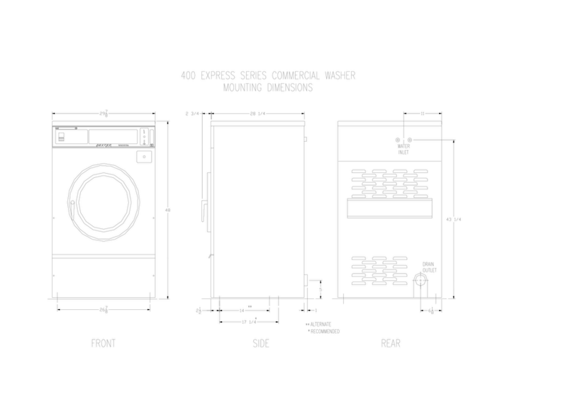
Dexter Laundry 400 EXPRESS User manual

Dexter Laundry

Dexter Laundry 400 EXPRESS User manual

Dexter Laundry OPL Series Quick start guide

Dexter Laundry

Dexter Laundry OPL Series Quick start guide

Dexter Laundry T350 User manual

Dexter Laundry

Dexter Laundry T350 User manual

Dexter Laundry WCN Series User manual

Dexter Laundry

Dexter Laundry WCN Series User manual

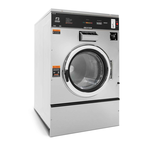
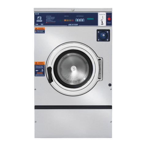
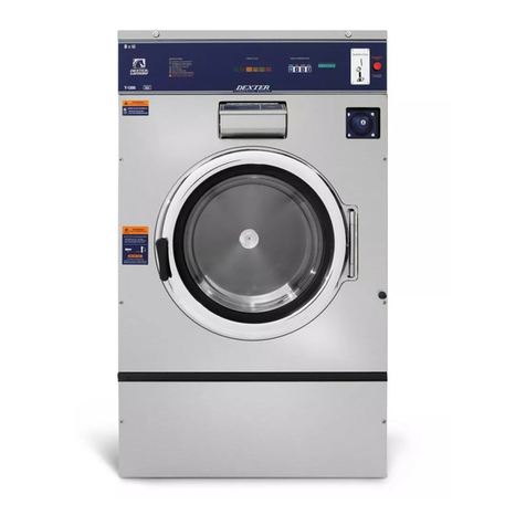
Dexter Laundry T-900 Quick start guide

Dexter Laundry

Dexter Laundry T-900 Quick start guide

Dexter Laundry WC Series Quick start guide

Dexter Laundry

Dexter Laundry WC Series Quick start guide

Dexter Laundry T-300 VENDED Quick start guide

Dexter Laundry

Dexter Laundry T-300 VENDED Quick start guide

Dexter Laundry T-300 VENDED User manual

Dexter Laundry

Dexter Laundry T-300 VENDED User manual

Dexter Laundry WCAD Series Quick start guide

Dexter Laundry

Dexter Laundry WCAD Series Quick start guide

Dexter Laundry WC 00XA-12EC X Series User manual

Dexter Laundry

Dexter Laundry WC 00XA-12EC X Series User manual

Dexter Laundry T450 Express User manual

Dexter Laundry

Dexter Laundry T450 Express User manual

Dexter Laundry O Series Quick start guide

Dexter Laundry

Dexter Laundry O Series Quick start guide

Dexter Laundry HIGH SPEED 25LB WASHER Installation instructions

Dexter Laundry

Dexter Laundry HIGH SPEED 25LB WASHER Installation instructions

Dexter Laundry T350 User manual

Dexter Laundry

Dexter Laundry T350 User manual

Dexter Laundry 75LB CAPACITY COMPUTER CONTROL OPL WASHER User manual

Dexter Laundry

Dexter Laundry 75LB CAPACITY COMPUTER CONTROL OPL WASHER User manual

Dexter Laundry WCVD Series Administrator guide

Dexter Laundry

Dexter Laundry WCVD Series Administrator guide

Dexter Laundry WN0675 Quick start guide

Dexter Laundry

Dexter Laundry WN0675 Quick start guide

Dexter Laundry T1200 Installation instructions

Dexter Laundry

Dexter Laundry T1200 Installation instructions

Popular Washer manuals by other brands

GE WNRD2050GWC Dimensions and installation information

GE

GE WNRD2050GWC Dimensions and installation information

Electrolux WH6-8CV instructions

Electrolux

Electrolux WH6-8CV instructions

Ariston WML 700 Instructions for use

Ariston

Ariston WML 700 Instructions for use

Kenmore 970L4814 Series Use & care guide

Kenmore

Kenmore 970L4814 Series Use & care guide

Samsung WW9 T3 Series user manual

Samsung

Samsung WW9 T3 Series user manual

Candy AQUA1142D User instructions

Candy

Candy AQUA1142D User instructions

Beko WTE 7611 BWR user manual

Beko

Beko WTE 7611 BWR user manual

Baumatic BFWM1406W 60 cm6kg instruction manual

Baumatic

Baumatic BFWM1406W 60 cm6kg instruction manual

Simpson SWT1012A user manual

Simpson

Simpson SWT1012A user manual

Bosch WFR 2830 Instruction manual and installation instructions

Bosch

Bosch WFR 2830 Instruction manual and installation instructions

Westinghouse WWF8025DQWA user manual

Westinghouse

Westinghouse WWF8025DQWA user manual

Haier RWT350AW Service manual

Haier

Haier RWT350AW Service manual

AEG OKO-LAVAMAT 76669 update User information

AEG

AEG OKO-LAVAMAT 76669 update User information

Samsung WF45B6300AC user manual

Samsung

Samsung WF45B6300AC user manual

Miele W 3037WH Operating and installation instructions

Miele

Miele W 3037WH Operating and installation instructions

Whirlpool LA98OOXP Use & care guide

Whirlpool

Whirlpool LA98OOXP Use & care guide

BENDIX BIW 80 Operating & installation instructions

BENDIX

BENDIX BIW 80 Operating & installation instructions

Bosch WAU28QP9SN User manual and installation instructions

Bosch

Bosch WAU28QP9SN User manual and installation instructions

manuals.online logo
manuals.online logoBrands
  • About & Mission
  • Contact us
  • Privacy Policy
  • Terms and Conditions

Copyright 2025 Manuals.Online. All Rights Reserved.