Deye GE-FL60 User manual
0
Installation and Operation Installations
High Voltage Battery
GE-FL60
Version: V1.1

1
Table of contents
All Rights Reserved................................................................................................... 3
About This Manual .................................................................................................... 3
1 Safety Precautions................................................................................................. 4
1.1 Personal Requirements ................................................................................... 4
1.2 Electrical Safety............................................................................................... 5
1.3 Battery Safety.................................................................................................. 6
1.4 Hoisting and Transportation............................................................................. 6
1.5 Installation and Wiring...................................................................................... 6
1.6 Operation and Maintenance............................................................................. 7
1.7 Disposal of Waste............................................................................................ 7
2 Product Description................................................................................................ 7
2.1 Product Introduction......................................................................................... 7
2.2 External Design ............................................................................................... 9
2.3 Air-conditioner Design.................................................................................... 10
2.4 Internal Design............................................................................................... 11
2.4.1 Internal Equipment ................................................................................................11
2.4.2 Battery Introduction...............................................................................................13
2.4.3 Indicator light Design .............................................................................................16
3 Transport and storage.......................................................................................... 19
3.1 Transportation................................................................................................ 19
3.2 Transportation Requirement .......................................................................... 19
3.3 Storage requirement...................................................................................... 20
4 Mechanical Installation......................................................................................... 21
4.1 Inspection Before Installation......................................................................... 21
4.1.1 Open the package ..................................................................................................21
4.1.1 Deliverables Inspection ..........................................................................................24
4.1.2 Product Inspection .................................................................................................24
4.2 Installation Environment................................................................................. 25
4.3 Installation Spacing Requirement................................................................... 26
4.4 Installation of inverters and BESS.................................................................. 28
4.5 Transportation and lifting ............................................................................... 29
4.5.1 Transportation........................................................................................................29
4.5.2 Hoisting Equipment................................................................................................31
4.5.3 Hoisting ..................................................................................................................32
4.6 Fixing Methods .............................................................................................. 33
5. Electrical connection ........................................................................................... 34
5.1 Electrical connection Overview ...................................................................... 34
5.2 Preparation before connection....................................................................... 35

2
5.4 Cable connection........................................................................................... 36
5.4.1 Cable connections inside BESS ...............................................................................36
5.4.2 Auxiliary power supply...........................................................................................39
5.4.3 Cable connection between BESS............................................................................34
5.4.4 Cable connection between the inverter and BESS .................................................35
5.5 Operation after cable connection ................................................................... 35
5.6 Battery Connection ........................................................................................ 36
6 Activate BESS...................................................................................................... 36
Power on and off.................................................................................................. 36
6.1 Power-on procedure ...................................................................................... 36
6.2 Power-off procedure ...................................................................................... 37
6.3 Unplanned (emergency) shut down ............................................................... 38
7 Fire Suppression system...................................................................................... 38
7.1 Fire Suppression equipment.......................................................................... 38
7.1.1 Aerosol fire suppression system.............................................................................39
7.1.2 Fire suppression water pipe system.......................................................................39
7.2 Exhaust system ............................................................................................. 41
8 Troubleshooting ................................................................................................... 41
9. Inspection and maintenance................................................................................ 42
9.1 Basic Information........................................................................................... 42
9.2 Maintenance item and period......................................................................... 43
9.3 Battery Maintenance...................................................................................... 44
9.4 Disassembly and installation.......................................................................... 46
9.4.1 Disassemble and install the battery pack...............................................................46
9.4.2 Disassemble and install the PDU............................................................................48
10 Upgrade ............................................................................................................. 50
10.1 USB Upgrade............................................................................................... 50
10.2 PC Upgrade................................................................................................. 50
10.3 PCS Upgrade............................................................................................... 53
11. Battery recycling................................................................................................ 55
11.1 Recovery process and steps of cathode materials....................................... 55
11.2 Recovery of anode materials ....................................................................... 55
11.3 List of recycling equipment........................................................................... 56
12 Contact Information............................................................................................ 56
12.1 System Parameter....................................................................................... 56
12.2 Contact Information...................................................................................... 57

3
All Rights Reserved
No part of this document can be reproduced in any form or by any means without the prior
written permission of NINGBO DEYE ESS TECHNOLOGY CO., LTD (-hereinafter "Deye ESS").
Trademarks
Deye and other Deye trademarks used in this manual are owned by Deye ESS.
All other trademarks or registered trademarks mentioned in this manual are owned by their
respective owners.
Software Licenses
•It is prohibited to use data contained in firmware or software developed by Deye ESS, in part
or in full, for commercial purposes by any means.
•It is prohibited to perform reverse engineering, cracking, or any other operations that
compromise the original program design of the software developed by Deye ESS.
About This Manual
This manual describes the transportation and storage, mechanical installation, electrical
connection, power-on and power-off operation, troubleshooting, and maintenance of the BESS.
How to Use This Manual
Please read this manual carefully before using the product and keep it properly at a place for
easy access.
In order to provide the best customer experience, contents of the manual may be updated and
amended continuously, so it is possible that there may be some errors or slight inconsistency
with the actual product. Please refer to the actual product purchased, and the latest manual can
be obtained from service-ess@deye.com.cn (www.deyeess.com) or sales channels.
The figures in this manual are for reference only. The actual product received may differ.
Symbol Explanations
To ensure the safety of the users and their properties when they use the product and to make
sure that the product is used in an optimal and efficient manner, this manual provides users with
the relevant safety information highlighted by the following symbols.
Below is a list of symbols used in this manual. Please read it carefully to make better use of this
manual.
4
Danger!
Failure to follow the instructions bearing this sign may result in a serious
accident resulting in death or serious injury.
Warning!
Failure to follow the instructions of this sign may result in a serious accident
resulting in serious personal injury.
Caution!
Failure to follow the instructions of this sign may result in minor or
moderate injury.
Notice!
Provide information that is considered important but not relevant to the
danger. The information relates to property damage.
This product is designed to an integrated system, which must be performed by a qualified person
trained in electrical engineering and familiar with the characteristics and safety requirements of
lithium batteries. Do not use this product if you are unsure if you possess the necessary skills to
complete this integration.
Abbreviation:
Complete designation
Abbreviations
Battery Module
Module
Battery Pack
Pack
Power Distribution Unit
PDU
Accessory box
/
Energy Storage System
BESS
Battery Base
Base
Manual service disconnect
MSD
1 Safety Precautions
1.1 Personal Requirements
The hoisting, transportation, installation, wiring, operation, and maintenance of the BESS must
be carried out by professional electrical technicians in accordance with local regulations. The
professional technician is required to meet the following requirements:
•Should know electronic, electrical wiring and mechanical expertise, and be familiar with
electrical and mechanical schematics.
•Should be familiar with the composition and working principles of the BESS and its corollary
equipment.
•Be able to quickly respond to hazards and emergencies that occur during installation and
commissioning.
•Be familiar with the relevant standards and specifications of the country/region where the
project is located.

5
1.2 Electrical Safety
Danger!
•Touching the power grid or the contact points and terminals in the devices connected to the
power grid may lead to electric shock! All circuit connectors must be disconnected during
maintenance.
•The battery side or the power grid side may generate voltage. Always use a standard
voltmeter to ensure that there is no voltage before touching.
Danger!
•Lethal voltages are present inside the product!
•Note and observe the warnings on the product.
•Respect all safety precautions listed in this manual and other pertinent document.
•Respect the protection requirements and precautions of the lithium battery
Danger!
When the power supply is disconnected, there may still be electricity in the battery. Wait for 10
minutes and ensure that the device has no voltage before performing any operation.
Warning!
•All hoisting, transportation, installation, wiring, operation, and maintenance must be carried
out complying with the relevant codes and regulations of the country where the project is
located.
•Always use the product in accordance with the requirements described in this manual.
Otherwise, equipment damage may occur.

6
Notice!
To prevent accidents caused by misuse or unrelated persons, place necessary warning signs or
barriers near the product.
1.3 Battery Safety
It is very important to read the owner's manual carefully before installing or using the battery.
Follow any instructions or warnings in this document, otherwise it may result in electric shock,
serious injury, or death, or may damage the battery and render it inoperable.
After the battery is fully discharged, it needs to be charged within 48 hours. The battery is not
charged as required, resulting in loss of battery capacity or irreversible damage. If the battery is
stored for a long time, it is required to be charged every six months, and the SOC should not be
less than 50%.
•Do not use cleaning solvents to clean batteries. Do not expose the battery to flammable or
irritating chemicals or vapors.
•Do not connect the battery directly to the photovoltaic solar power wire.
•Do not paint any part of the battery, including any internal or external components.
•Please do not use batteries provided by the company with other batteries, including but not
limited to batteries of other brands or batteries with different rated capacities.
•Do not insert any foreign matter into any part of the battery.
•Handle or handle with care to avoid battery damage, drop, or leakage.
•Do not store batteries with inflammable and explosive materials. This may cause product
damage or property loss.
Maintain the battery according to this manual. Deye ESS is not responsible for insurance and
claims if maintenance is not performed in accordance with this manual.
1.4 Hoisting and Transportation
Follow the procedure of work of heights when walking on the top of the container.
1.5 Installation and Wiring
In the whole process of mechanical installation, the relevant standards and requirements of the
project location must be strictly observed.
Please refer to the wiring method recommended by Deye ESS.

7
1.6 Operation and Maintenance
Personal protective equipment must be equipped when maintaining and maintaining the BESS.
Maintenance personnel must wear protective equipment such as goggles, helmets, insulating
shoes, and gloves.
Users are not allowed to perform battery maintenance without guidance. Warning Except the
maintenance operations described in this manual, do not perform other maintenance operations
to avoid electric shock. If necessary, please contact Deye ESS Customer Service center for
maintenance.
Removing or repairing the battery may cause the battery to catch fire. The replacement of
internal parts must be carried out by professionals. Do not spray paint internal or external parts
of the product. Do not use cleaning agents to clean products or expose them to harsh chemicals.
1.7 Disposal of Waste
When the equipment is at the end of its service life, it cannot be disposed of together with
domestic waste. Some parts can be recycled, and some parts will cause environmental pollution.
2 Product Description
2.1 Product Introduction
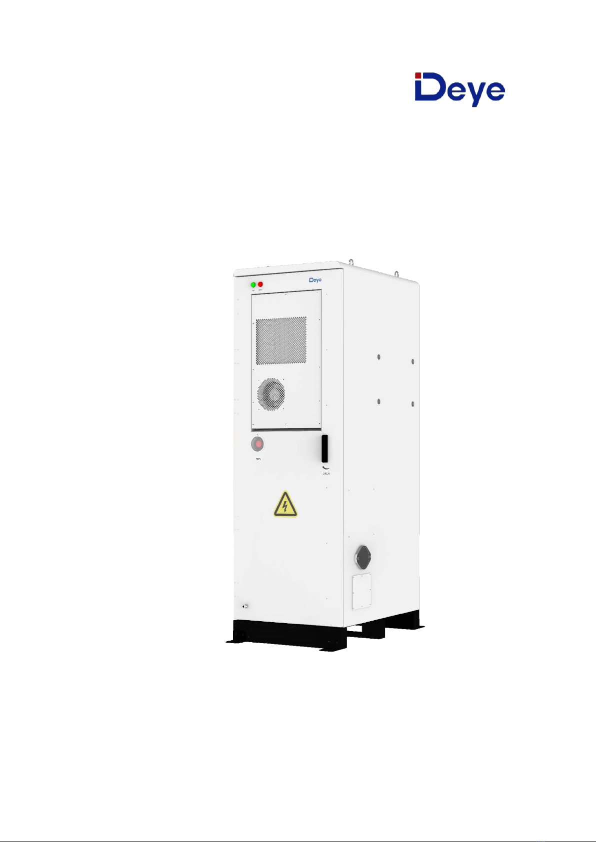
GE-FL60 lithium iron phosphate battery the new energy storage products developed and
produced by DEYE ESS, which can be used to support the reliable power supply of various
equipment and systems. The GE-FL60 is particularly suitable for high-rate cyclic charging and
discharging scenarios.
GE-FL60 has built-in local management system, it can manage and monitor, voltage, current,
temperature, humidity, smoke, etc. In addition, BMS also balances the capacity of the battery
and extends the cycle life of the system. Meanwhile, support black start function, Off grid
operation, and built-in aerosol fire suppression device and combustible gas detection exhaust
system. Multiple battery systems can be expanded in parallel for greater capacity and longer
power support duration requirements.

9
2.2 External Design
Cabinet Appearance
①
Indicator light: When the green light
comes on, the BESS is Run. When the
red light comes on, the BESS gives an
alarm.
⑥
Door switch: Insert the key to open the ESS.
②
Air conditioning outlet: Hot air in the air
conditioner comes out from this outlet.
⑦
Air outlet: When combustible gas is detected
the BESS, it can be discharged through this
outlet. And the outlet will automatically pop out
and need to be manually reset after use.
③
Air conditioning inlet: Outdoor air enters
air conditioner through this opening.
⑧
Cable outlet: The cable outlet during parallel
operation or connected to the inverter.
④
Emergency stop switch: When the BESS
out of order, activate this switch to stop
the BESS.
⑨
Air inlet: When combustible gas is detected,
the inlet will automatically pop out and need to
be manually reset after use.
⑤
Water outlet: Air conditioning
condensed water.

10
2.3 Air-conditioner Design
System built-in air conditioner cooling
The air conditioning system uses air cooled air conditioner, keep the BESS at a constant
temperature.
Energy storage Air Conditioning
Model
DY-CNA20-BP(US)
Rated Voltage
AC 240V
Rated Frequency
60Hz
Rated Cooling Capacity
2100W
Rated Cooling Current
4.15A
Rated Cooling Power Input
900W
Rated Heating Capacity
1650W
Rated Heating Power Input
1700W
Rated Heating Current
7.9A
Minimum Circuit Ampacity
5.3A
Maximum Overcurrent Protection
10A
Rated Current of Power conversion
equipment
8.5A
Max Operating Pressure
2.7Mpa
Max.Suction Pressure
1.6Mpa
Max.Discharge Pressure
2.7Mpa
Air Flow Volume
630m
³
/h
Electric Shock Prevention
I
Water-proof Class
IP55
Refrigerant
R134a/330g
Dimension
(
W
×
H
×
D
)
478
×
798
×
304mm
Net Weight
48.5kg

11
2.4 Internal Design
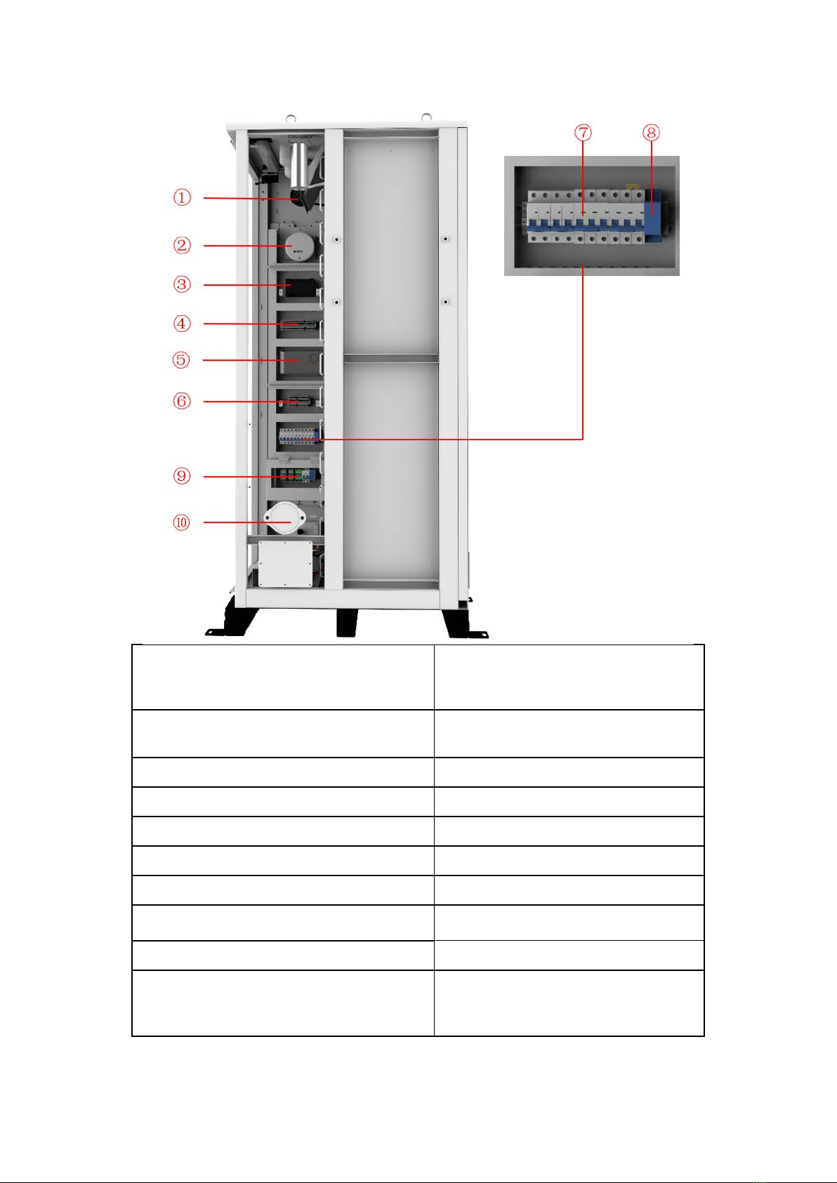
2.4.1 Internal Equipment
①
Air conditioner
Cooling the BESS.
②
Travel switch
Check whether the BESS system door is closed.
③Smoke detector
A device used to detect smoke in a fire and sound
an alarm when smoke is detected.
④Heat detector
A device used to measure temperature and
sound an alarm if it detects excessive
temperature.
⑤
Fire suppression water pipe
Fire suppression and cooling.
⑥Aerosol fire extinguishing device
When the BESS is detected to be on fire, aerosol
is emitted to extinguish the fire.
⑦Manual service disconnect
In order to protect the safety of technicians
servicing in high voltage environments or
respond to sudden events, the connection of the
high voltage circuit can be quickly separated.
12
①Air outlet
When combustible gas is detected, the
outlet will automatically pop out and
need to be manually reset after use.
②Combustible gas sensor
Detect combustible gases and notify
aerosol fire suppression systems
③Serial relay
Control system
④Terminal line
For connecting cables
⑤Switching Mode Power Supply
Power source
⑥Terminal line
For connecting cables
⑦Miniature circuit breaker
Controlled power-on and power-off
⑧Water immersion sensor Check the BESS for water leakage
⑨Terminal line
Connect external cables
⑩Air inlet
When combustible gas is detected, the
inlet will automatically pop out and need
to be manually reset after use.

13
2.4.2 Battery Introduction
Battery Module
Battery Type
Nominal Voltage
Rated Capacity
Rated Energy
Nominal Charge/Discharge Current
Peak. Discharge Current
Charge Temperature
Discharge Temperature
Storage Temperature
Ingress Protection
Dimension (W/D/H)
Weight Approximate
LiFePO4(LFP)
51.2Vdc
100Ah
5.12kWh
100A
125A
0~55°C
-20℃~55°C
0℃~35°C
IP20
440*570*133mm
45kg

14
①Aerosol sensor
Detection of aerosol concentrations in the
air
②Battery module
Provides electrical energy storage and
output
③CCS
Cells Contact System
④Vent hole
Heat dissipation
⑤Battery Negative-
/
⑥Battery Positive+
/
⑦Fan
Promote internal and external air flow
⑧BMU
Battery monitoring
Power Distribution Unit
Operating Voltage
Nominal Charge/Discharge Current
Max. Charge/Discharge Current
DC Input Rating
Operating Temperature Range
Ingress Protection
Dimension (W/D/H)
Weight Approximate
120
~
750Vdc
100A
125A
12±2%V/4.15A
-20~65°C
IP20
440*570*150mm
19kg
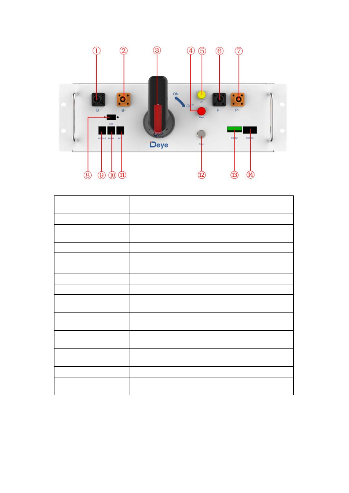
15
①B-
Connection position of the common negative pole of the
battery
②B+
Connection position of the common positive pole of the battery
③DC switch
Used to manually control the connection between the battery
rack and external devices
④ALRM light indicator
Battery system fault alarm indicator
⑤HV light indicator
High-voltage hazard indicator
⑥PCS-
Connection position of PCS negative pole
⑦PCS+
Connection position of PCS positive pole
⑧USB
BMS upgrade interface and storage expansion interface
⑨OUT COM
Connection position with next GE-F-PDU communication
output
⑩IN COM
Connection position with previous GE-F-PDU communication
input
⑪PCS COM
Communication interface with charging and discharging
equipment
⑫START
A start switch of 12VDC power inside the high-voltage control
box
⑬COMM1
Communicative connection with the cabinet
⑭COMM2
Communicative connection with the first battery module; and
providing 12VDC power for the first battery module

16
2.4.3 Indicator light Design
Indicator light: When the green light comes on, the BESS is Run. When the red light comes on,
the BESS gives an alarm.
1. The following faults trigger either level 2 fault. The cabinet ALARM red light is on, the external
ALARM light is on, and the RUN indicator is off.
1 System fault 17
Total voltage too high
fault
33 Voltage acquisition fault
2 Charging current fault 18
Discharge relay
adhesion
34
Temperature acquisition
fault
3 Charging current fault 19
Charge relay
adhesion
35 Emergency stop press fault
4
Charging
overtemperature fault
20
Heating relay
adhesion
36
Detected combustible gas
fault
5
Discharging
overtemperature fault
21 Extreme protection 37
Detected water sensor
fault
6
Charging low
temperature fault
22
Abnormal supply
voltage
38
Detected smoke sensor
fault
7
Discharging low
temperature fault
23
Main positive relay
adhesion
39 Pre-charge failed fault
8
Pressure difference
24
blown fuse
40
The Charging voltage is too

17
too large fault
low
9
Temperature
difference too large
fault
25 BMU repeat fault 41 BMU communication fault
10
High SOC fault
26
BMU repeat fault
42
BMU number anomaly
11
Cell temperature low
voltage fault
27
Internal CAN
communication fails
43
Abnormal Mot total
pressure collection
12 Pre-charge resistance
temperature too high 28 PCS CAN
Communication fails 44
Abnormal Temperature
collection of the BMS
connector
13 Insulation fault 29 Abnormal PCS RS485
communication 45
Abnormal Temperature
collection of the BMU
connector
14 Heating film is too
high fault 30
Abnormal external
total pressure
collection
46 EEPROM storage fault
15 SOC too low fault 31
Abnormal internal
total pressure
collection
47 RTC clock fault
16
Total voltage too high
fault
32
Abnormal SCHG total
pressure collection
48 Current module fault
49 Current acquisition fault
2. When the emergency stop press fault, flammable gas fault, water flooding fault and smoke
fault are detected, the BESS external ALARM light is on and the RUN light is off.
3. The air conditioner is offline, the BESS external ALARM light is on, and the RUN light is off.
4. The following faults occur in the air conditioner. The BESS external ALARM light is on and the
RUN light is off.
1
High temperature alarm
9
Internal ambient
temperature 1 fault
17
Inner coil temperature
protection
2
Low temperature alarm
10
Internal ambient
temperature 2 fault
18
Internal fan failure
3
High humidity alarm
11
Internal ambient
humidity 1 fault
19
Internal fan
communication fault
4
Low humidity alarm
12
Internal ambient
humidity 2 fault
20
Internal fan overloaded
fault
5
Electric heating
protection
13
Inner coil temperature
fault
21
External fan failure
6
Outdoor ambient
temperature fault
14
Pressure sensor failure
22
External fan
communication fault
7
Outer coil temperature
fault
15
High exhaust
temperature protection
23
External fan
overloaded fault
8
Exhaust temperature
fault
16
Outer coil temperature
protection
24
Compressor startup
failure
25
Compressor
communication failure

18
Indicator: Steady yellow indicates that PDU is working properly and the battery power circuit is
closed. When the red light is on, PDU gives an alarm.
The following faults trigger any level 2 fault, the battery ALARM red light is on, the PDU ALARM
light is on, and the HV indicator is off.
1 System fault 17
Total voltage too high
fault
33 Voltage acquisition fault
2 Charging current fault 18
Discharge relay
adhesion
34
Temperature acquisition
fault
3 Charging current fault 19
Charge relay
adhesion
35 Emergency stop press fault
4
Charging
overtemperature fault
20
Heating relay
adhesion
36
Detected combustible gas
fault
5
Discharging
overtemperature fault
21 Extreme protection 37
Detected water sensor
fault
6
Charging low
temperature fault
22
Abnormal supply
voltage
38
Detected smoke sensor
fault
7
Discharging low
temperature fault
23
Main positive relay
adhesion
39 Pre-charge failed fault
8
Pressure difference
too large fault
24 blown fuse 40
The Charging voltage is too
low
9
Temperature
difference too large
fault
25 BMU repeat fault 41 BMU communication fault
10
High SOC fault
26
BMU repeat fault
42
BMU number anomaly
11
Cell temperature low
voltage fault
27
Internal CAN
communication fails
43
Abnormal Mot total
pressure collection
12 Pre-charge resistance
temperature too high 28 PCS CAN
Communication fails 44
Abnormal Temperature
collection of the BMS
connector
13 Insulation fault 29 Abnormal PCS RS485
communication 45
Abnormal Temperature
collection of the BMU
connector
14 Heating film is too
high fault 30
Abnormal external
total pressure
collection
46 EEPROM storage fault
15 SOC too low fault 31
Abnormal internal
total pressure
collection
47 RTC clock fault
16
Total voltage too high
32
Abnormal SCHG total
48
Current module fault

19
fault
pressure collection
49 Current acquisition fault
3 Transport and storage
3.1 Transportation
1 Preventive Measures
Failure to ship and store products in accordance with the requirements of this manual may void
the warranty.
2 Mode of Transportation
It can be transported by cars, trains and ships.
3.2 Transportation Requirement
The following conditions should be met for the transportation of BESS:
Ensure that the door is locked.
Select appropriate crane or lifting tool according to the site conditions. The lifting tool used
shall have a sufficient load bearing capacity, boom length and radius of rotation.
Additional traction may be required if ESS needs to be transported on slopes.
Remove all obstacles that exist or may exist on the way, such as tree branches, cables, etc.
The BESS should be transported and moved under good weather conditions.
Be sure to set up warning signs or warning area to prevent non-staff from entering the lifting
area to avoid accidents.
When transporting by road, it is important to use ropes to secure the top ring of the
equipment to the transport vehicle to avoid excessive tilt during transportation.
The battery products should be transported after packaging and during the transportation
process, severe vibration, impact, or extrusion should be prevented to prevent sun and rain. It
can be transported using vehicles such as cars, trains, and ships.
Always check all applicable local, national, and international regulations before transporting a
Lithium Iron Phosphate battery.
Transporting an end-of-life, damaged, or recalled battery may, in certain cases, be specially
limited or prohibited.
The transport of the Li-Ion battery falls under hazard class UN3480, class 9. For transport over
water, air and land, the battery falls within packaging group PI965 Section I.
Use Class 9 Miscellaneous Dangerous Goods and UN Identification labels for transportation of
lithium-ion batteries which are assigned Class 9. Refer to relevant transportation documents.
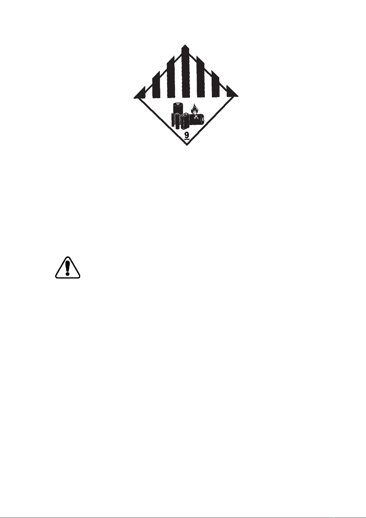
20
Class 9 Miscellaneous Dangerous Goods and UN Identification Label
3.3 Storage requirement
•During the rainy season to prevent possible condensation or its bottom being soaked by rain.
•BESS should be stored on higher ground. Raise container bases based on site conditions. The
specific height should be reasonably determined according to the geological and
meteorological conditions of the site.
•Stored on dry, flat, stable ground with sufficient carrying capacity and without any vegetation
cover.
•The ground must be flat and dry. Before storage, ensure that BESS’s door is locked.
•Storage ambient temperature:-30℃~60℃, recommended storage temperature:-30℃~25℃.
Notice! : To ensure battery life, keep the storage temperature of the battery module
between 0 ° C and 35 ° C
•Storage If the battery energy storage system is not used for a long time, please refer to the
following table to save power. After charging is complete, turn off all switches of the battery
energy storage system to ensure the lowest power consumption of the system.
•The relative humidity should be between 0 and 95% without condensation.
•The inlet and outlet of BESS should be effectively protected to prevent rain, sand and dust
from penetrating into. Check equipment regularly for damage.
This manual suits for next models
1
Table of contents
Other Deye Batteries Pack manuals


Popular Batteries Pack manuals by other brands


Pylontech
Pylontech RT12100B-G31 user manual

Aegis
Aegis ALF-048075A user manual

NOCO Genius
NOCO Genius NLP User guide & warranty

Vist
Vist VORHUT 34-263 user manual

True blue power
True blue power TB40 Series Installation manual and operating instructions

Bosch
Bosch PowerPack Frame 800 Original operating instructions


