Deye GB-SL10K-EU User manual

R
ALL IN ONE ESS
User Manual
GB-SL10K-EU
GB-SL8K-EU
GB-SL6K-EU
GB-SL5K-EU
GB-SL12K-EU
GB-SL15K-EU
GB-SL20K-EU

1. Safety Introductions
2. Product instructions
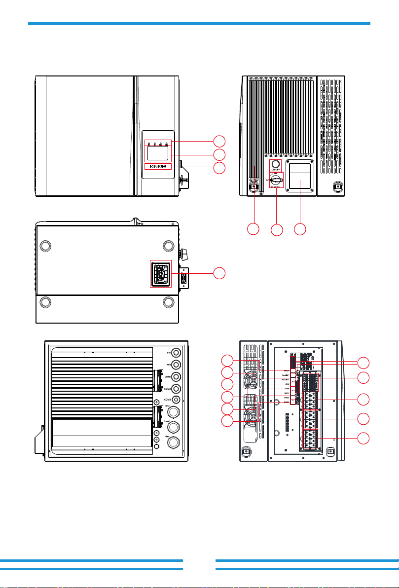
2.1 Product Overview
…………………………………………………
…………………………………………………
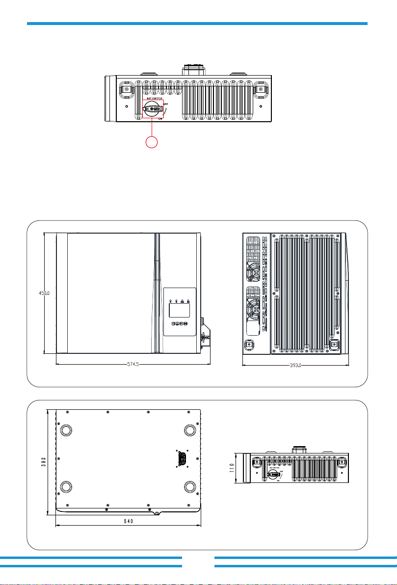
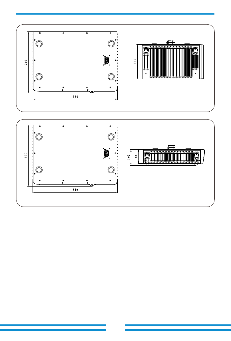
2.2 Product Size
01
01-05
Contents
……………………………………………………………
2.3 Product Features
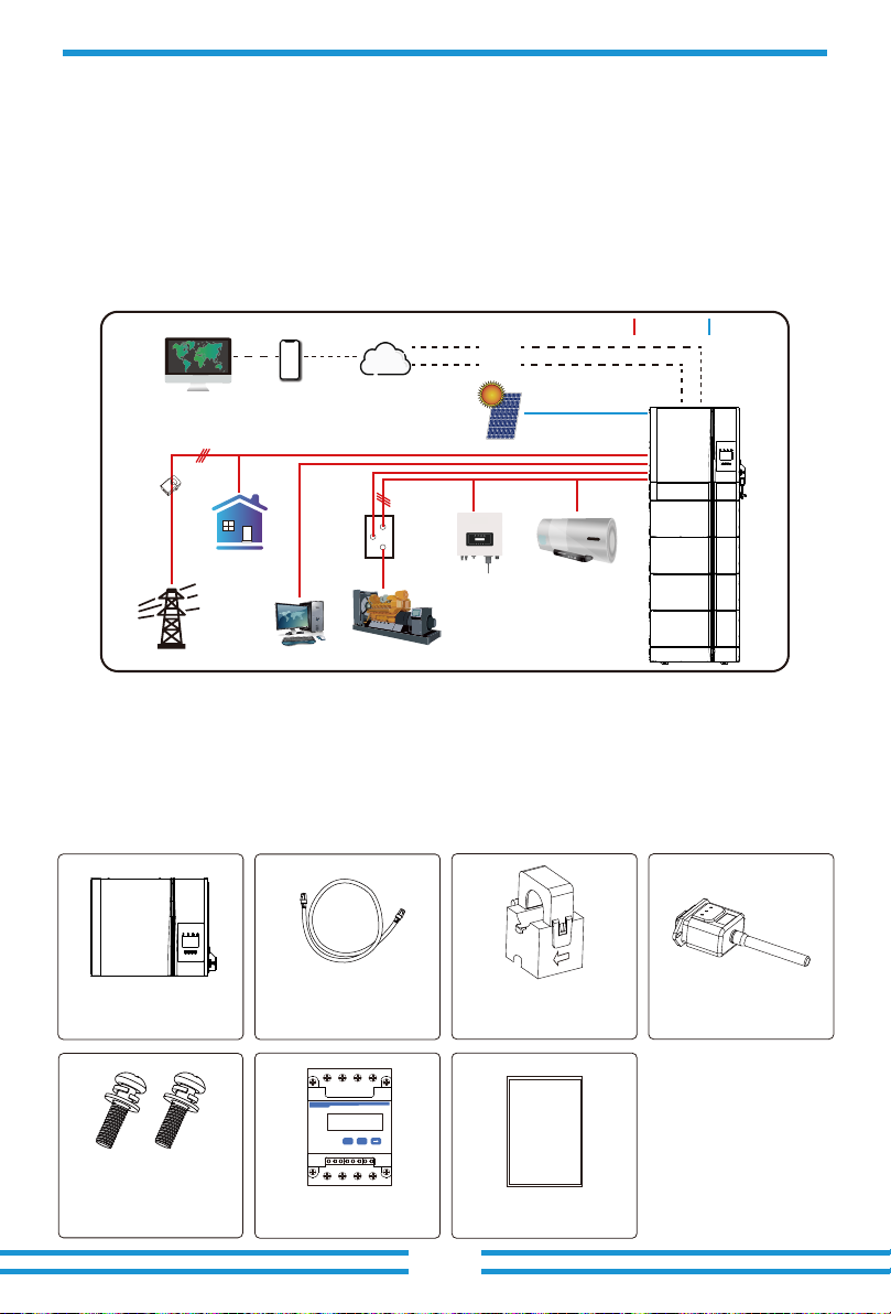
2.4 Basic System Architecture
3. Installation
3.1 Parts list
3.2 Mounting instructions
3.3 Battery connection
3.5 PV Connection
3.4 Grid connection and backup load connection
05-26
3.6 CT Connection
3.7 Earth Connection(mandatory)
3.8 WIFI Connection
3.9 Wiring System for Inverter
3.11 Typical application diagram of diesel generator
3.10 Wiring diagram
3.12 phase parallel connection diagram
……………………………………………………………………
6. Mode 40-41
5.6 Battery Setup Menu
5.7 System Work Mode Setup Menu
5.8 Grid Setup Menu
5.9 Generator Port Use Setup Menu
5.10 Advanced Function Setup Menu
5.11 Device Info Setup Menu
……………………………………………………………
……………………………………………………
4. OPERATION
4.1 Power ON/OFF
4.2 Operation and Display Panel
5. LCD Display Icons
5.1 Main Screen
5.2 Solar Power Curve
27-28
28-40
5.4 System Setup Menu
5.5 Basic Setup Menu
5.3 Curve Page-Solar & Load & Grid
………………………………………………
………………………………………………………………
7. Limitation of Liability
8. Datasheet
41-45
46-47
……………………………………………………………
9. Appendix I 48-49
……………………………………………………………
10. Appendix II 50
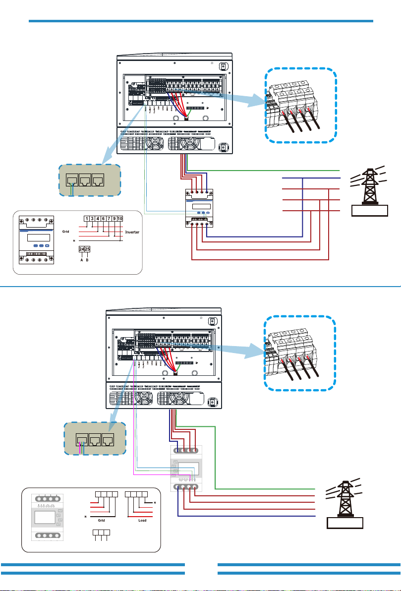
3.6.1 Meter Connection

- 01 -
- 02 -
2
3
1
7
8
12
11
10
15
14
13
9
16
17
18
456
- 03 -
2.2 Product Size
1
- 04 -
- 05 -
Three-Phase Smart Meter
SET ESC
Generator
Solar
Grid Backup Load
On-Grid
Home Load
AC cable DC cable
WiFI
GPRS
phone Cloud services
ATS
Smart Load
CT
Grid-connected
nverter

- 06 -
(
)
()
()
()
()
- 07 -
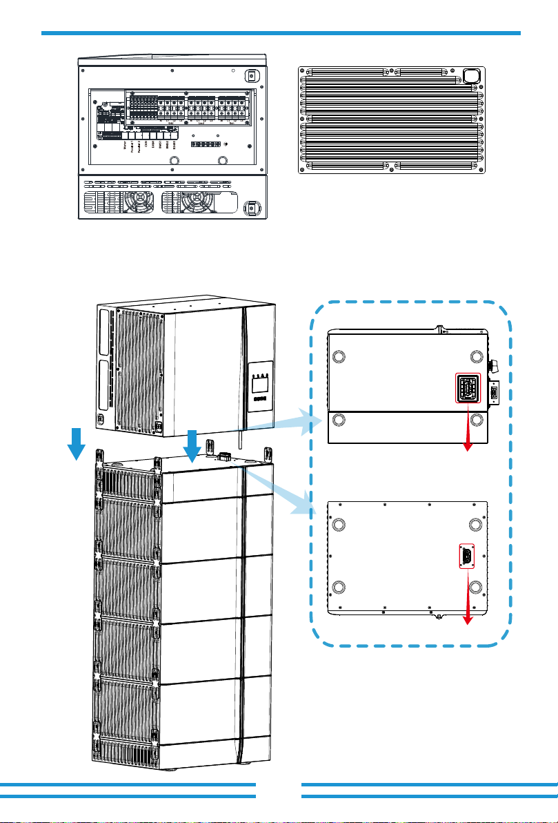
Battery Port
Battery Port

- 08 -
℃℃
:
:
- 09 -
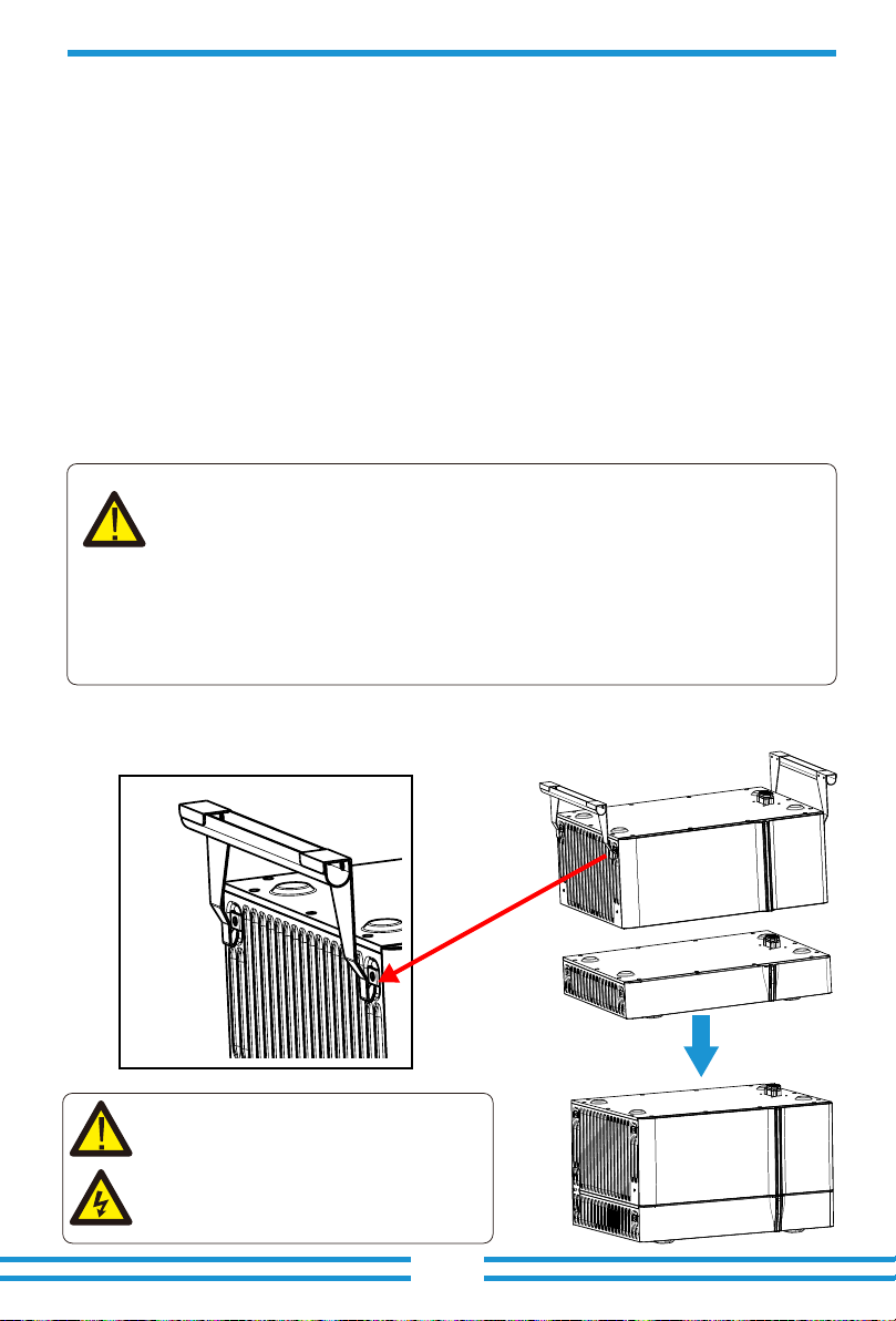
CAUTION!
- 10 -
...
- 11 -

- 12 -
()
()
()

- 13 -
1 2 3 4 5 6 7 8 9 10 1112 1 2 3 4 5 6 7 8 9 10 1112
.
.
.
CT -S
CT -T
CT -R
Gen start-up
N/O Relay
Parallel_1 Parallel_2Meter CAN DRM BMS1 BMS2 RS485
GS (diesel generator startup signal)
relay
coil
open
contact
G S
CN1 CN2
SHUT DOWN
B B
- 14 -
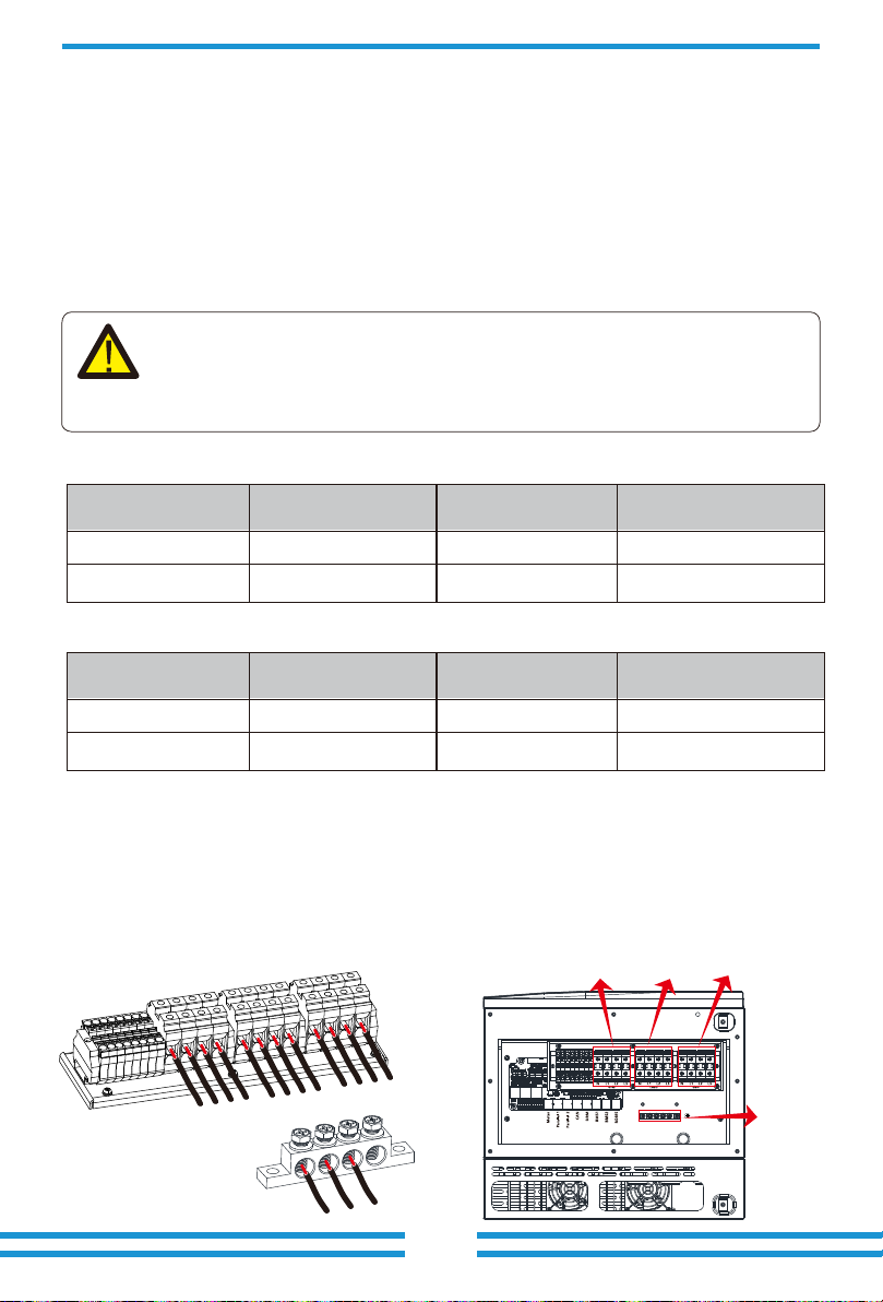
GRID
GRID
E-BAR
LOAD
LOAD GENGEN
E-BAR
L3
L2
L1
N
Model
Wire Size
Cable(mm )
2
10
Torque value(max)
25
Model
Wire Size
Cable(mm )
2
10
Torque value(max)
25
L3
L2
L1
NNL3
L2
L1
PE PE PE
- 15 -
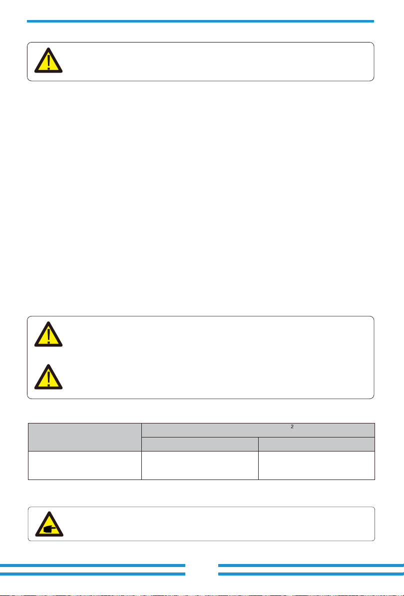
Safety Hint:
Cable type Range Recommended value
Cross secon(mm )

- 16 -
Inverter Model
2
10KW8KW
6KW
5KW
12KW 15KW 20KW
PV1+ PV1- PV2+ PV2-
1 2 3 4 5 6 7 8 9 10 1112
- 17 -
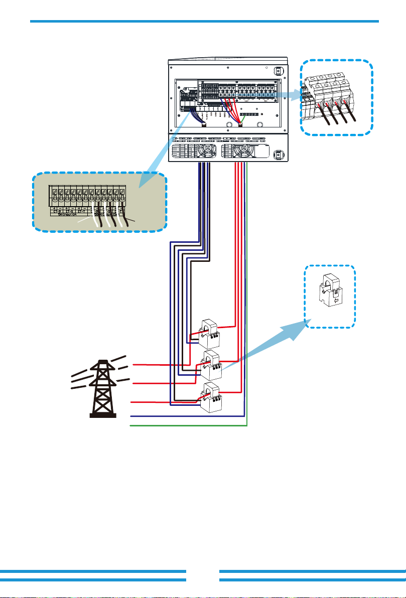
White wire Black wire
CT
Arrow pointing
to inverter
*Note:
Grid
N
PE
L1
L2
L3
CT1
CT2
CT3
GRID
L3
L2
L1
N
- 18 -
L1
L2
L3
N
PE
RS485A
RS485B
Three-Phase Smart Meter
SET ESC
1 74 10
2524
3
96 10
Three-Phase Smart Meter
SET ESC
1 74 10
2524
3 96 10
RS 485
CHNT DTSU666
(3,6,9,10)
(1,4,7,10)
L1
L2
L3
Grid
L1
L1
L2
L2
L3
L3
N
N
RS485A
RS485B
Grid
Eastron meterEastron SDM630-Modbus V2
RS 485
RS 485 B RS 485 A
B A G
(5,6,7,8)
(1,2,3,4)
1234
L1
L2
L3
5678
GND
Eastron
5 6 7 8
L1
L2
L3
Eastron
5 6 7 8
PE
GND
Parallel_1 Parallel_2Meter
Parallel_1 Parallel_2Meter
GRID
L3
L2
L1
N
GRID
L3
L2
L1
N
This manual suits for next models
6
Table of contents
Other Deye Batteries Pack manuals


