DeZurik D10350 User manual

DeZURIK
D10350 © 2014 DeZURIK, Inc.
Instructions
These instructions provide information about Switch and Position Transmitters. They are for use by
personnel who are responsible for installation, operation and maintenance of Switch and Position
Transmitters.
Safety Messages
All safety messages in the instructions are flagged with an exclamation symbol and the word Caution,
Warning or Danger. These messages indicate procedures that must be followed exactly to avoid
equipment damage, personal injury or death. Safety label(s) on the product indicate hazards that can
cause equipment damage, personal injury or death. If a safety label becomes difficult to see or read, or
if a label has been removed, please contact DeZURIK for replacement label(s).
Personnel involved in the installation or maintenance of valves should be constantly
alert to potential emission of pipeline material and take appropriate safety precautions.
Always wear suitable protection when dealing with hazardous pipeline materials. Handle
valves, which have been removed from service with suitable protection for any potential
pipeline material in the valve.
Inspection
Your Switch and Position Transmitter has been packaged to provide protection during shipment,
however, it can be damaged in transport. Carefully inspect the unit for damage upon arrival and file a
claim with the carrier if damage is apparent.
Parts
Recommended spare parts are listed on the assembly drawing. These parts should be stocked to
minimize downtime.
Order parts from your DeZURIK sales representative, or directly from DeZURIK. When ordering parts,
please include the 7-digit part number and 4-digit revision number (example: 9999999R000) located on
the data plate attached to the valve assembly. Also include the part name, the assembly drawing
number, the balloon number and the quantity stated on the assembly drawing.
DeZURIK Service
DeZURIK service personnel are available to install, maintain and repair all DeZURIK products.
DeZURIK also offers customized training programs and consultation services.
For more information, contact your local DeZURIK sales representative or visit our website at
www.dezurik.com.

DeZURIK
May 2014 Page 3 D10350
Table of Contents
Description - - - - - - - - - - - - - - - - - - - - - - - - - - - - - - - - - - - - - - - - - - - - - - - - - - - - -
4
Electrical Connections - - - - - - - - - - - - - - - - - - - - - - - - - - - - - - - - - - - - - - - - - - - - -
4
Mechanical Switches - - - - - - - - - - - - - - - - - - - - - - - - - - - - - - - - - - - - - - - - - - - - - -
4
Proximity Switches - - - - - - - - - - - - - - - - - - - - - - - - - - - - - - - - - - - - - - - - - - - - - - -
5
Position Transmitter - - - - - - - - - - - - - - - - - - - - - - - - - - - - - - - - - - - - - - - - - - - - - -
6
Indicator Adjustment - - - - - - - - - - - - - - - - - - - - - - - - - - - - - - - - - - - - - - - - - - - - - -
7
Switch Mounting Kit used on PMV Positioner - - - - - - - - - - - - - - - - - - - - - - - - - - - -
8
DeZURIK
D10350 Page 4 May 2014
Description
This valve accessory provides electrical functions in response to the open, closed, and intermediate
positions of a 2-way valve or a 2-position 3-way valve. Electrical switching and variable current
functions are provided in selected combinations. The adjustable sensing devices are mechanically
linked to a valve, a valve actuator, or a positioner.
Components are located in a sealed and accessible aluminum enclosure, constructed to comply with
NEMA types 4, 4X, 7 and 9. The position of the valve is visibly displayed in two windows at 180°
viewing angles. Three basic options consisting of mechanical switches, proximity switches, and a
position transmitter are provided individually or in selected combinations. The three options are
described below.
Electrical Connections
Field wiring enters through ¾" and ½" NPT electrical connections to a prewired and labeled terminal
strip as described in the following sections. One ½" pipe plug is provided with the unit. If the ½"
connection is not used, install the pipe plug tightly in the connection. Do not use thread sealant.
Mechanical Switches
The two SPDT or four SPDT mechanical snap-acting switches each have a rating of:
Silver Contacts -10 Amps at 125/250 VAC, or 0.5 Amp at 125 VDC.
Gold Contacts - 1 Amp at 125 VAC, or 0.5 Amp at 30 VDC
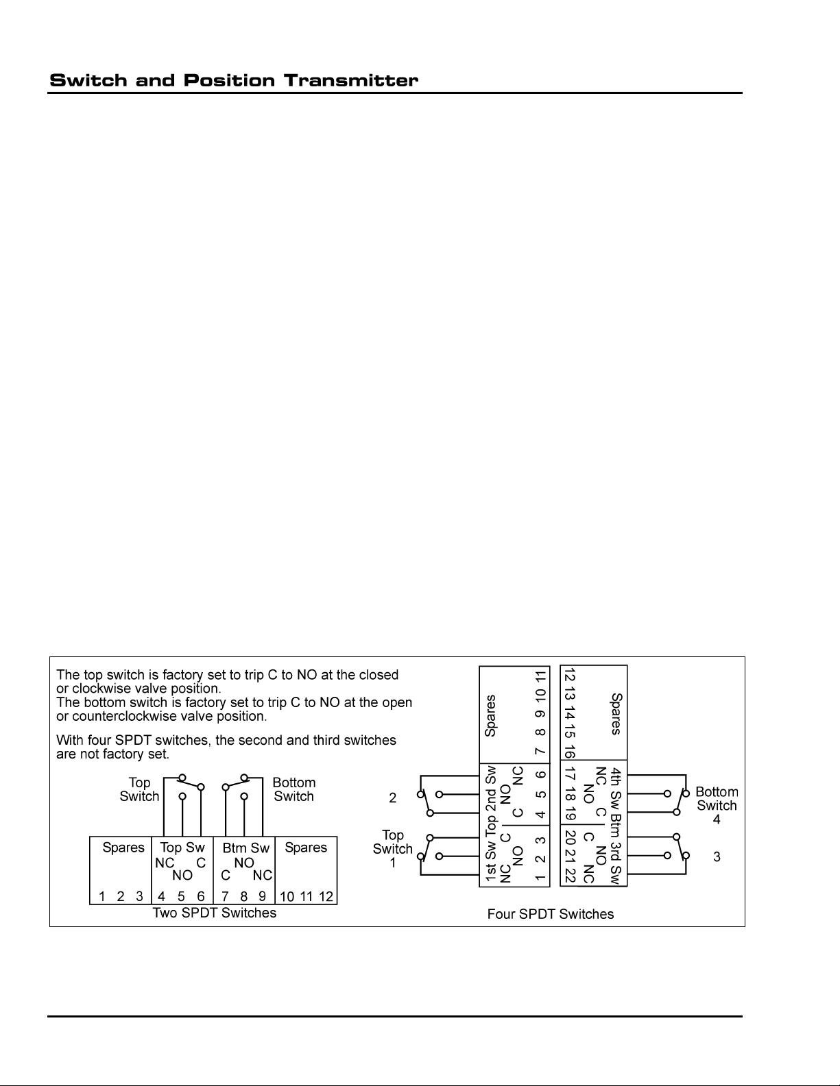
With two SPDT switches, the top switch is factory set to trip as the valve reaches the closed or
clockwise position, and the bottom switch is factory set to trip as the valve reaches the open or counter-
clockwise position. The internal wiring from the switches to the terminal strip is shown in Figure 1.
With four SPDT switches, the top (first) switch is factory set to trip as the valve reaches the closed or
clockwise position, and the bottom (fourth) switch is factory set to trip as the valve reaches the open or
counterclockwise position. The second and third switches are not factory set, but may be set in the
field. The internal wiring from the switches to the terminal strip is shown in Figure 2.
Figure 1—Mechanical Switches
DeZURIK
May 2014 Page 5 D10350
Mechanical Switches (Continued)
Each switch is actuated by a rotating cam. To adjust a top switch, push the top cam down, rotate it to
the desired position, and release the cam so it engages into the new position on the spline. To adjust a
bottom switch, repeat the process with the bottom cam, but lift the cam upwards to rotate it to the
desired position. Each cam may be further fine-tuned between spline positions by turning the set screw
on the cam with a 1/16" hex driver. The set screw is limited to adjustment of no more than one full turn.
Proximity Switches
The two SPDT proximity switches each has a rating of 0.3 amp at 120 VAC, or 0.2 amp at 30 VDC. The
switch contacts are sealed for low-energy switching of solid-state signal circuits.
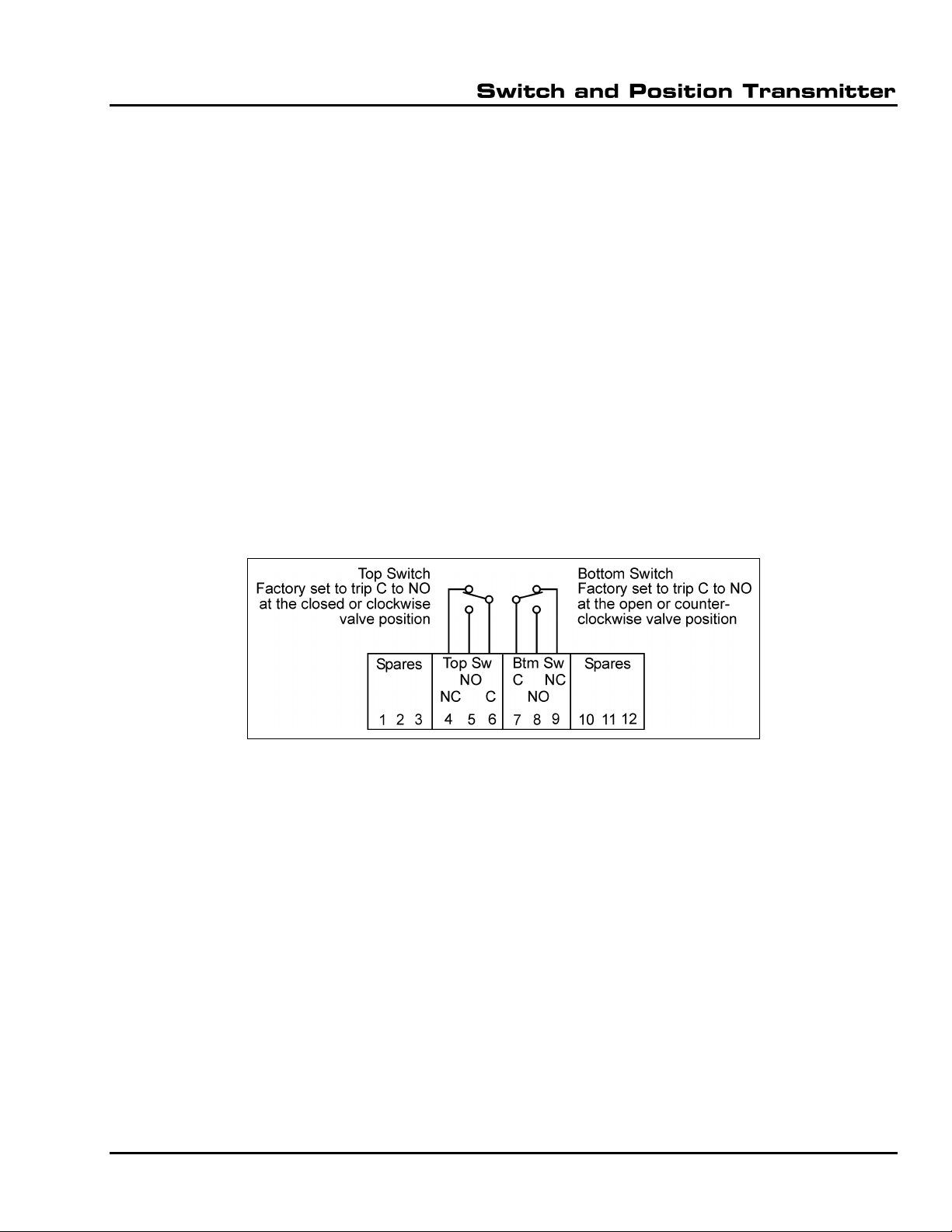
The top switch is factory set to trip as the valve reaches the closed or clockwise position, and the
bottom switch is factory set to trip as the valve reaches the open or counterclockwise position. The
internal wiring from the switches to the terminal strip is shown in Figure 2.
Each switch is actuated as the white stripe on its rotating cam aligns with the white stripe on the switch.
To adjust the top switch, push the top cam down, rotate it to the desired position, and release the cam
so it slides into the new position on the spline. To adjust the bottom switch, repeat the process with the
bottom cam, but lift the cam upwards to rotate it to the desired position.
Figure 2—Proximity Switches

DeZURIK
D10350 Page 6 May 2014
Position Transmitter
The position transmitter provides a 4 to 20 mA output signal with the plus and minus terminals
connected in series with an external 24 VDC power supply. Voltage variations from 10 VDC to 40 VDC
do not affect the current signal. The maximum load is 700 ohms at 24 VDC. The unit is calibrated as
shown in the following steps. Refer to Figure 3 for component identification.
1. Plug the 3-pin potentiometer connector into the appropriate 3 pins on the 5-pin block as
described in Figure 3. The 5-pin block is located next to the span adjustment.
2. Place the valve in the position desired for 4 mA output. Do not connect power until step 4. If the
valve is in the closed or clockwise position, connect an ohmmeter to terminals 2 and 3 of the
potentiometer; if the valve is in the open or counterclockwise position, connect an ohmmeter to
terminals 1 and 2 of the potentiometer.
3. Loosen the coupling that drives the potentiometer shaft, and rotate the potentiometer so that the
ohmmeter reads 500 ± 100 ohms. Then tighten the coupling, and disconnect the ohmmeter from
the potentiometer.
4. Connect a 20 mA ammeter and a 24 VDC power supply to terminals + and –as shown in Figure
3.
5. Adjust the zero trimpot so that the ammeter reads 4 ± 0.1 mA.
6. Place the valve in the position desired for 20 mA output. Adjust the span trimpot so that the
ammeter reads 20 ± 0.1 mA. The zero and span adjustments are not interactive.
Figure 3—Position Transmitter
DeZURIK
May 2014 Page 7 D10350
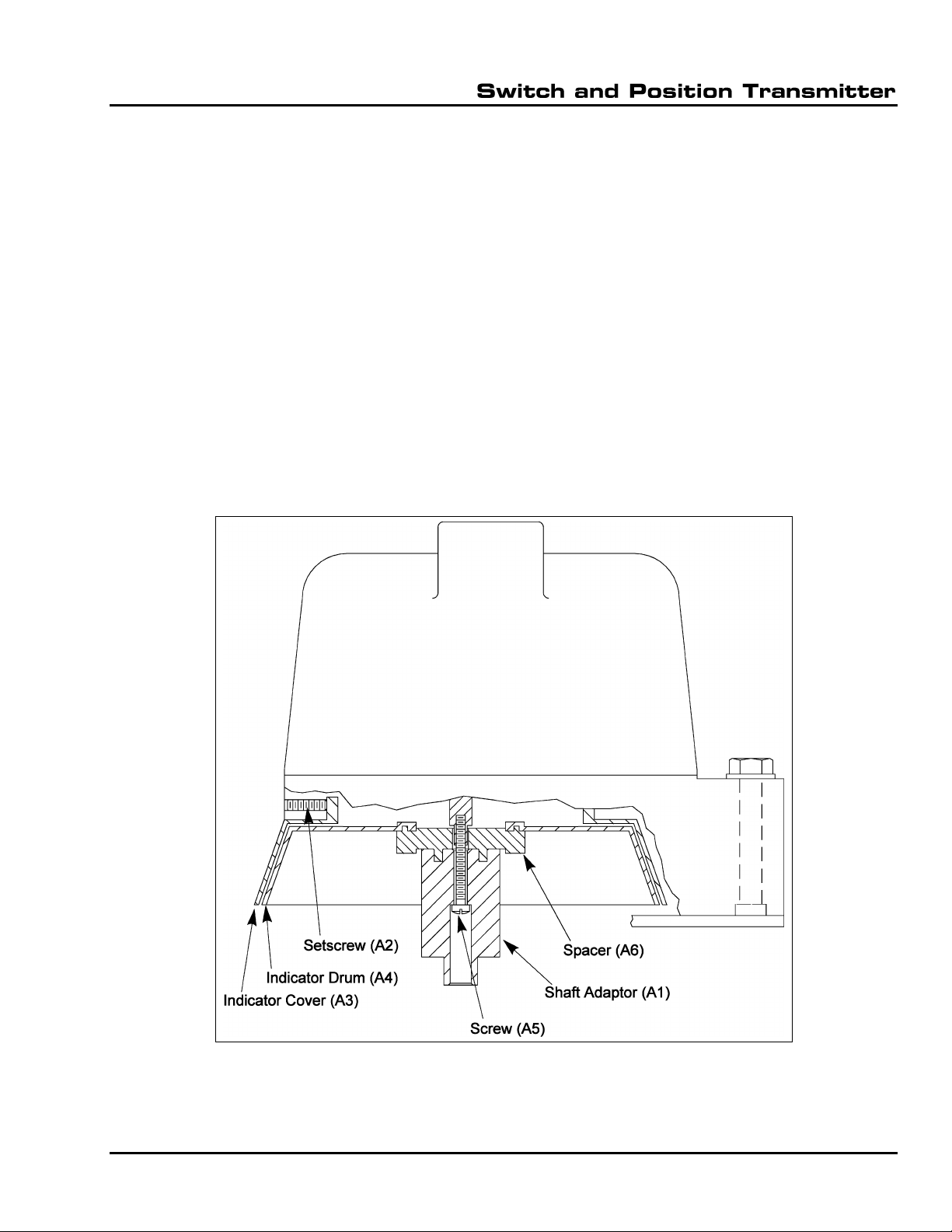
Indicator Adjustment
The open-closed indicator on all units, shown in Figure 4 as indicator drum (A4), may be re-indexed on
the input shaft as follows:
1. Remove the two mounting screws and washers near the conduit connection, and lift the unit
from position so that the bottom of the unit is accessible.
2. Loosen the screw (A5) about 3 turns.
3. Pull out the spacer (A6) and shaft adaptor (A1) so that the spacer pins are disengaged from the
timing holes in the indicator drum (A4). (The shaft adaptor may be a different size and/or shape
than shown in Figure 3.)
4. Rotate the indicator drum (A4) to the desired position, and push the shaft adaptor (A1) and
spacer (A6) towards the indicator drum (A4) to engage the spacer pins with the nearest timing
holes in the indicator drum. Tighten the screw (A5) to 8 ± 2 inch pounds.
5. Replace the unit in the same mounting position with the two screws and washers, and tighten
the screws to 80 ± 5 inch pounds.
6. To fine-tune the position of the indicator cover (A3), loosen the set screw (A2), and rotate the
indicator cover to the desired position. Tighten the set screw.
Figure 4 - Indicator Adjustment Components

DeZURIK
D10350 Page 8 May 2014
Switch Mounting Kit used on PMV Positioner
Figure 5 –Switch Mounting Kit used on PMV Positioner

Limited Warranty
DeZURIK, Inc. (“Seller”) manufactured products, auxiliaries and parts for a period of twenty-four (24) months from date of shipment from
Seller’s factory, are warranted to the original purchaser only against defective workmanship and material, but only if properly stored, installed,
operated, and serviced in accordance with Seller’s recommendations and instructions.
For items proven to be defective within the warranty period, your exclusive remedy under this limited warranty is repair or replacement of
the defective item, at Seller’s option, FCA Incoterms 2020 Seller’s facility with removal, transportation, and installation at your cost.
Products or parts manufactured by others but furnished by Seller are not covered by this limited warranty. Seller will provide repair or
replacement for other’s products or parts only to the extent provided in and honored by the original manufacturer’s warranty to Seller, in
each case subject to the limitations contained in the original manufacturer’s warranty.
No claim for transportation, labor, or special or consequential damages or any other loss, cost or damage is being provided in this limited
warranty. You shall be solely responsible for determining suitability for use and in no event shall Seller be liable in this respect.
This limited warranty does not warrant that any Seller product or part is resistant to corrosion, erosion, abrasion or other sources of failure,
nor does Seller warrant a minimum length of service.
Your failure to give written notice to us of any alleged defect under this warranty within twenty (20) days of its discovery, or attempts by
someone other than Seller or its authorized representatives to remedy the alleged defects therein, or failure to return product or parts for
repair or replacement as herein provided, or failure to store, install, or operate said products and parts according to the recommendations
and instructions furnished by Seller shall be a waiver by you of all rights under this limited warranty.
This limited warranty is voided by any misuse, modification, abuse or alteration of Seller’s product, accident, fire, flood or other Act of God,
or your failure to pay entire contract price when due.
The foregoing limited warranty shall be null and void if, after shipment from our factory, the item is modified in any way or a component of
another manufacturer, such as but not limited to, an actuator is attached to the item by anyone other than a Seller factory authorized service
personnel.
All orders accepted shall be deemed accepted subject to this limited warranty, which shall be exclusive of any other or previous Warranty,
and this shall be the only effective guarantee or warranty binding on Seller, despite anything to the contrary contained in the purchase order
or represented by any agent or employee of Seller in writing or otherwise, notwithstanding, including but not limited to implied warranties.
THE FOREGOING REPAIR AND REPLACEMENT LIMITED WARRANTY IS IN LIEU OF ALL OTHER WARRANTIES, OBLIGATIONS AND
LIABILITIES, INCLUDING ALL WARRANTIES OF FITNESS FOR A PARTICULAR PURPOSE OR OF MERCHANTABILITY OR
OTHERWISE, EXPRESSED OR IMPLIED IN FACT OR BY LAW, AND STATE SELLER’S ENTIRE AND EXCLUSIVE LIABILITY AND YOUR
EXCLUSIVE REMEDY FOR ANY CLAIM IN CONNECTION WITH THE SALE AND FURNISHING OF SERVICES, GOODS OR PARTS,
THEIR DESIGN, SUITABILITY FOR USE, INSTALLATION OR OPERATIONS.
Disclaimer
Metric fasteners should not be used with ASME Class 150/300 bolt holes and flange bolt patterns. If you use metric fasteners with ASME
Class 150/300 bolt holes and flange bolt patterns, it may lead to product failure, injury, and loss of life. DeZURIK Inc. disclaims all liability
associated with the use of metric fasteners with ASME Class 150/300 bolt holes and flange patterns, including but not limited to personal
injury, loss of life, loss of product, production time, equipment, property damage, lost profits, consequential damages of any kind and
environment damage and/or cleanup. Use of metric fasteners with ASME Class 150/300 bolt holes and flange bolt patterns is a misuse that
voids all warranties and contractual assurances. If you use metric fasteners with ASME Class 150/300 bolt holes and flange bolt patterns,
you do so at your sole risk and any liability associated with such use shall not be the responsibility of DeZURIK, Inc. In addition to the
foregoing, DeZURIK’s Manufacturer’s Conditions apply.
Limitation of Liability
IN NO EVENT SHALL SELLER BE LIABLE FOR ANY DIRECT, INDIRECT, SPECIAL, PUNITIVE, OR CONSEQUENTIAL DAMAGES
WHATSOEVER, AND SELLER’S LIABILITY, UNDER NO CIRCUMSTANCES, WILL EXCEED THE CONTRACT PRICE FOR THE GOODS
AND/OR SERVICES FOR WHICH LIABILITY IS CLAIMED. ANY ACTION FOR BREACH OF CONTRACT BY YOU, OTHER THAN RIGHTS
RESPECTING OUR LIMITED WARRANTY DESCRIBED ABOVE, MUST BE COMMENCED WITHIN 12 MONTHS AFTER THE DATE OF
SALE. Sales and Service
For information about our worldwide locations, approvals, certifications and local representative:
250 Riverside Ave. N., Sartell, MN 56377 ● Phone: 320-259-2000 ● Fax: 320-259-2227
DeZURIK, Inc. reserves the right to incorporate our latest design and material changes without notice or obligation.
Design features, materials of construction and dimensional data, as described in this manual, are provided for your information only
and should not be relied upon unless confirmed in writing by DeZURIK, Inc. Certified drawings are available upon request.
Printed in U.S.A.
October 2021
Table of contents
Popular Transmitter manuals by other brands


Honeywell
Honeywell 5802mn2 - Ademco Wireless Panic user manual

Shure
Shure UR1M quick start guide

rojaflex
rojaflex WSR-15 Original assembly and operating instructions

Emerson
Emerson Rosemount 5402 Reference manual
Levil Aviation
Levil Aviation Beacon 978 Series Installation and Pilot's Guide

Steren
Steren MP3-050 instruction manual