DFA 127 User manual

DFA 127
User manual
Translation of the original manual

Document identification
Article nr.: 102-127401806
Version: V1.0
Publication date: 01/02/2022
Subject to technical modifications
Copyright © agtatec ag

Table of contents
BAL_DFA_127_EN_1V0_OEM_102-127401806 3 / 28
Table of contents
Glossary ............................................................................................................................................................ 4
1 Safety................................................................................................................................................................. 5
1.1 Presentation of warning signs............................................................................................................... 5
1.2 Intended purpose of use ....................................................................................................................... 5
1.3 General hazards ................................................................................................................................... 5
1.4 State of technology ............................................................................................................................... 8
1.5 Spare parts and liability ........................................................................................................................ 8
2 General information ......................................................................................................................................... 9
2.1 Purpose and use of the instructions ..................................................................................................... 9
2.2 Copyright .............................................................................................................................................. 9
2.3 Product identification ............................................................................................................................ 9
2.4 Manufacturer agtatec ag....................................................................................................................... 9
2.5 Target groups ....................................................................................................................................... 10
2.6 Definition of terms................................................................................................................................. 10
3 Description........................................................................................................................................................ 11
3.1 Overview............................................................................................................................................... 11
3.2 Types of arm......................................................................................................................................... 12
3.3 Low energy drive (Low Energy) ............................................................................................................ 12
3.4 Functions .............................................................................................................................................. 12
3.5 Primary / secondary application............................................................................................................ 13
3.6 Control panel ........................................................................................................................................ 13
3.7 Battery pack (optional).......................................................................................................................... 14
4 Specifications ................................................................................................................................................... 15
4.1 Tecnical data ........................................................................................................................................ 15
5 Operation........................................................................................................................................................... 16
5.1 Toggle switch BDI................................................................................................................................. 16
5.1.1 Control elements and displays......................................................................................................... 16
5.2 Control panel BDE-D ............................................................................................................................ 16
5.2.1 Operation modes and button functions ............................................................................................ 16
5.2.2 Perform reset ................................................................................................................................... 18
5.2.3 Display system information .............................................................................................................. 19
5.2.4 Lock control panel............................................................................................................................ 19
5.2.5 Set parameters ................................................................................................................................ 20
5.2.6 Description of parameters................................................................................................................ 21
6 Malfunctions ..................................................................................................................................................... 23
6.1 Status displays...................................................................................................................................... 23
6.2 Troubleshooting .................................................................................................................................... 23
7 Maintenance and servicing.............................................................................................................................. 25
7.1 Test log book ........................................................................................................................................ 25
7.2 General remarks ................................................................................................................................... 25
7.3 Operator duties ..................................................................................................................................... 25
7.4 Spare parts and wearing parts.............................................................................................................. 26

Glossary
4 / 28 BAL_DFA_127_EN_1V0_OEM_102-127401806
Glossary
BDE
Control panel
BDE-D
Bedienungseinheit mit Display
BDE-M
Control panel mechanical
BDI
Control unit with toggle switch
BDI-M
Print for mechanical control unit
NET
Power supply
SSK
Key pivot contact
STG
Control unit
Safety 1
BAL_DFA_127_EN_1V0_OEM_102-127401806 5 / 28
1 Safety
1.1 Presentation of warning signs
Various symbols are used in this guide for easier understanding:
NOTICE
Useful advice and information to ensure correct and efficient workflow of the system.
IMPORTANT
Specific details which are essential for trouble-free operation of the system.
IMPORTANT
Important details which must be read for proper function of the system.
CAUTION
Against a potential hazardous situation that can lead to minor personal injury and property
damage.
WARNING
Against a latent hazardous situation that can lead to severe injuries or death and cause sub-
stantial property damage.
DANGER
Against an imminent hazardous situation that can lead to severe injury or death.
DANGER
Against an imminent or latent hazardous situation that could lead to electric shock and cause
serious injury or death.
1.2 Intended purpose of use
The system is designed exclusively for use as a pedestrian passage. The installation must only occur
in dry areas. If there are deviations then proper waterproofing and water drains will be required on-
site.
Any other application or use beyond this purpose is not considered to be an intended purpose. The
manufacturer bears no liability for any resulting damage; the operator alone shall bear the associated
risk.
The intended purpose also includes observation of the operating conditions specified by the manufac-
turer, in addition to regular care, maintenance and repair.
Interventions in or alterations to the installation performed by non-authorized maintenance technicians
exclude the manufacturer's liability for consequential damages.
1.3 General hazards
The following section lists hazards that can be caused by the system even when used as intended.
To reduce the risk of malfunction, damage to property or injury to persons and to avoid dangerous
situations, the safety instructions listed here must be observed.
1Safety
6 / 28 BAL_DFA_127_EN_1V0_OEM_102-127401806
The specific safety instructions in the other sections of this manual must also be observed.
IMPORTANT
The country-specific regulations must be observed and complied with!
IMPORTANT
To avoid malfunctions, moving objects such as flags or parts of plants must not be allowed to
enter the detection range of the sensors.
CAUTION
Risk of malfunctions, material damage or injury due to improper settings!
a) Improper settings can lead to malfunctions, material damage or personal injury.
ðDo not disconnect the system from the power supply overnight.
ðSettings should only be made by personnel qualified to do so.
ðDo not disassemble, put out of operation or manipulate safety devices.
ðHave faults rectified by specialist personnel or by personnel qualified to do so.
ðHave service and maintenance carried out according to locally applicable regulations or accord-
ing to a maintenance contract.
CAUTION
Risk of malfunctions, material damage or injuries due to insufficient or missing cleaning or
care!
a) Insufficient or inattentive cleaning or care of the system can lead to malfunctions, damage to
property or injury to persons.
ðCheck the sensors regularly for dirt and clean them if necessary.
ðRegularly remove dirt accumulations in the floor rail or under the floor mat.
ðKeep the system free from snow and ice.
ðDo not use aggressive or caustic cleaning agents.
ðUse road salt or loose chippings only conditionally.
ðLay the floor mat without folds and flush with the floor.
ðEquipment required for cleaning purposes such as ladders or similar must not be leaned on or at-
tached to the system.
CAUTION
Risk of material damage or injury due to unforeseen opening, closing or turning of the door!
a) The door can open, close or turn unexpectedly. This may result in damage to property or injury
to persons.
ðNo persons may be present in the opening area of the system.
ðEnsure that moving objects such as flags or parts of plants do not enter the detection range of
the sensors.
ðDo not make any settings on the control unit when the system is in use.
ðHave faults rectified immediately by specialist or personnel qualified to do so.
ðRemove objects from the opening area.
ðDo not disassemble, put out of operation or manipulate safety devices.
ðDo not rush through a closing system.
Safety 1
BAL_DFA_127_EN_1V0_OEM_102-127401806 7 / 28
CAUTION
Risk of bruising and severing of limbs!
a) If the system moves, careless behaviour can lead to serious injuries to limbs or severance of
limbs.
ðDo not reach in when parts of the system are moving.
ðKeep a distance when parts of the system move.
ðDo not bump into or touch the system when it is moving.
ðDo not open or remove protective covers during operation.
ðDo not permanently remove covers from the system.
ðOnly carry out inspection, service, maintenance and cleaning when the system is stationary and
switched off.
CAUTION
Danger of material damage or injury due to non-functioning safety devices!
a) If safety devices are not functioning, manipulated or put out of operation, there is a risk of dam-
age to property or injuries that can lead to death.
ðNever disable or manipulate safety devices.
ðHave inspection, service and maintenance of the safety devices carried out according to local
regulations or according to a maintenance contract.
CAUTION
Danger of malfunctions, damage to property or risk of injury if used by unauthorised persons!
a) If unauthorised persons use the system, there is a risk of malfunction, damage to property or in-
jury to persons.
ðChildren under 8 years of age may only use the system under supervision.
ðChildren must not play, clean or maintain the system.
ðPersons with limited physical, sensory or mental abilities as well as persons with insufficient
knowledge or experience may only use the system under supervision or must have received and
understood instructions to do so.
DANGER
Danger to life due to electric current!
a) In case of contact with live parts, there is an immediate danger to life due to electric shock.
Damage to or removal of the insulation or individual components can be life-threatening.
ðBefore starting work on active parts of electrical systems and equipment, ensure that all poles are
voltage free and that this is maintained for the duration of the work.
ðKeep moisture away from live parts. This can lead to a short circuit.
ðNever bridge fuses or put them out of operation.
ðDo not connect the power supply until all work has been completed.
ðHave work on the electrical system performed by qualified personnel only.

1Safety
8 / 28 BAL_DFA_127_EN_1V0_OEM_102-127401806
DANGER
Danger to life due to non-functioning safety devices of the fire protection system!
a) If safety devices of the fire protection system do not function properly, there is a risk of serious
or fatal injuries.
ðNever disconnect the fire protection system from the power supply overnight.
ðDo not disassemble, put out of operation or manipulate safety devices.
ðDo not remove safety instructions on the system.
ðNever block, hold open or otherwise prevent fire doors from closing.
ðHave inspection, service and maintenance of the fire protection system carried out in accordance
with locally applicable regulations or according to a maintenance contract.
ðHave the fire protection system checked and maintained according to the state of the art.
1.4 State of technology
This system was developed using state of the art technology and officially recognized technical safety
regulations. The system, depending on its options and diameter, comply with the requirements of the
Machine Guidelines 2006/42/EG as well as EN 16005 and DIN 18650 (D).
Nevertheless, danger may arise if not used as intended.
IMPORTANT
Installation, commissioning, inspection, maintenance and repair work may only be conducted
by qualified, trained and authorized technicians.
After commissioning or repair work, fill in the check list and give it to the customer for safe
keeping.
We recommend obtaining a service agreement.
1.5 Spare parts and liability
Reliable and trouble free operation of the door is only guaranteed when using parts that were recom-
mended by the manufacturer. The manufacturer declines any liability for damages resulting from un-
authorized modifications to the door or the use of parts that are not permitted.

General information 2
BAL_DFA_127_EN_1V0_OEM_102-127401806 9 / 28
2 General information
2.1 Purpose and use of the instructions
These instructions are an integral part of the system and enable efficient and safe handling of the sys-
tem. In order to ensure proper functioning, the instructions must be accessible at all times and kept in
the immediate area of the system.
Although only the male form has been chosen for reasons of better legibility, the information refers to
members of both sexes.
The operator must have read and understood the manual before starting any work. The basic require-
ment for safe working is to follow the safety instructions and the handling instructions. In addition, the
local regulations and safety rules apply.
The manual can be handed over in extracts to instructed personnel who are familiar with the opera-
tion of the system.
The illustrations are for basic understanding and may differ from the actual presentation. Specific rep-
resentations are contained in the drawings.
2.2 Copyright
The copyright for these instructions remains with:
agtatec ag
The instructions may not be reproduced, distributed, or used for the purpose of competition without
the written consent of agtatec ag.
Infringements shall result in the obligation to pay damages.
2.3 Product identification
For precise identification, please refer to the nameplate attached to the inside of the casing or to the
operator displaying the following information:
Example:
Type:
Serial number:
Year of construction:
Mains connection:
Power consumption:
Classification according to
18650-1:2005:
Marking:
2.4 Manufacturer agtatec ag
agtatec ag
Allmendstrasse 24
CH – 8320 Fehraltorf
Switzerland
Phone: +41 44 954 91 91
Fax: +41 44 954 92 00
2General information
10 / 28 BAL_DFA_127_EN_1V0_OEM_102-127401806
2.5 Target groups
CAUTION
Risk of injury if personnel are insufficiently qualified!
If unqualified personnel work on the system or are in the danger zone of the system, dangers may
arise which can cause serious injuries and considerable damage to property.
a) All work must be carried out by qualified personnel only.
b) Keep unqualified personnel away from danger areas.
This operating manual is intended for the target groups listed below:
– Operating entity of the system:
the person who is responsible for the technical maintenance of this system
– Operator of the system:
the person who operates the system every day and has been suitably instructed
2.6 Definition of terms
Term: Explanation:
System The term is also used in these instructions as a synonym for
the product. Door operators, revolving doors, sliding doors,
etc. are referred to as a system.
If information in these instructions refers to a specific type, this
is shown accordingly in the text.
User Users are all persons who use the system.
System operator The respective owner is referred to as the system operator, re-
gardless of whether they operate the system as the owner or
pass it on to third parties.
Authorized representative The authorized representative takes over certain parts of the
manufacturer's obligations with regard to fulfilling the require-
ments of the Machinery Directive. In particular, the authorized
representative may also place the system on the market and/
or sign EC declarations of incorporation.
Qualified personnel are authorized and appropriately trained to perform the following work:
– Disassembly, Assembly, Commissioning, Operation, Audit, Maintenance, Troubleshooting, De-
commissioning
The qualified personnel have several years of professional experience in the technical field, e.g. as
mechanics or machine fitters.
The qualified personnel are aware of the residual risks arising from the installation site and, due to
their professional training, knowledge and experience, are able to carry out the work assigned to
them and to independently identify and avoid possible danger points.
Manufacturer The manufacturer is whoever designs and/or builds machinery
or incomplete machinery under the scope of the Machinery
Directive.
Life phases All phases of the system's condition and use are referred to as
life phases. This applies from the time the system leaves the
factory until it is disposed of.
Personnel All persons who carry out activities on and with the system are
referred to as personnel. Personnel can be, for example, the
operator, the cleaning staff, or the security staff. The personnel
meet the personnel qualifications required by the manufac-
turer.
Description 3
BAL_DFA_127_EN_1V0_OEM_102-127401806 11 / 28
3 Description
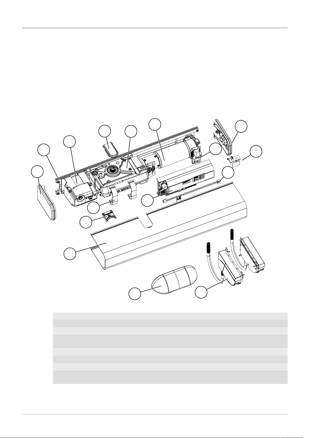
3.1 Overview
The swing door operator DFA 127 (hereinafter referred to as operator), is a self-monitored, micropro-
cessor-controlled swing door operator. It can be used in a multitude of ways thanks to its special and
additional functions.
The microprocessor analyzes the current door position, door speed, and target position and calcu-
lates the movement sequence. This means that there are no jerky braking movements or creep rate,
and end stops for the door are eliminated. The spring force must be adjusted depending on door leaf
width.
Set parameters [}20]
Description of parameters [}21]
1
3
45
67
8
9
11
10
12
13
14
15 16
2
1 Side cover 2 Chassis
3 Power supply unit NET 4 Shaft cover
5 Drive group ATG 6 Motor MOT
7 Side cover with toggle switch 8 Print for mechanical control panel BDE-M
(option)
9 Cable SIP 220 mm 10 Motor print
11 Control device STG 12 Wedge
13 Cable clip 14 Casing
15 Sensor RAD 290 (option) 16 Sensor BEA Flatscan left and right (op-
tion)

3Description
12 / 28 BAL_DFA_127_EN_1V0_OEM_102-127401806
3.2 Types of arm
Power is transmitted from the operator to the door leaf by means of an arm. Depending on the install-
ation situation, a standard arm or a sliding arm may be suitable. Standard arms are available in vari-
ous lengths to adjust the recess depth. Varying over heights are adjusted with the lever sockets (shaft
extensions).
Standard arm SG
2
1
1 Lever socket 2 Adjusting screw length
Sliding arm GG
2
1
3
4
1 Stop plate with damper stop 2 Pin shaft
3 Slide shoe 4 Lever socket
3.3 Low energy drive (Low Energy)
Parameterization makes it possible to use the operator as a low-energy operator.
The door is closed with reduced spring force. The opening and closing speeds can be adjusted to a
limited extent and the operator reacts more sensitively in the event of a collision. To prevent acci-
dental or improper changes to the programming, access to the parameters is restricted for users.
Only qualified personnel may carry out the parameterization of the operator.
3.4 Functions
Obstacle detection: If the door hits an obstacle when opening, it stops immediately and saves the
position of the collision. During the hold open time, the operator briefly attempts to reach the open po-
sition. Once the hold open time has elapsed, the door closes and the obstacle position is passed over
more slowly the next time it opens. This prevents another hard impact.
Description 3
BAL_DFA_127_EN_1V0_OEM_102-127401806 13 / 28
Reversing: If the door hits an obstacle when closing, a reopening is initiated immediately (reversing).
The obstacle position is saved in the door operator and this position is approached gently the next
time the door is closed.
Operation: Three operation modes can be set using the built-in toggle switch BDIToggle switch BDI
[}16].
Primary / secondary: A primary / secondary system can only be operated via the toggle switch BDI
of the primary operator. This switch position also affects the secondary operator.
3.5 Primary / secondary application
Primary
Secondary
Active leafInactive leaf
With the primary / secondary application, the
opening and closing sequence of two-leaf doors is
controlled electronically.
For two-leaf fire doors, the mechanical door selector SFR 127 is additionally installed for the inactive
leaf and the active leaf.
The two operators communicate with each other via an interface so that the safety functions such as
reversing and obstacle detection remain in place.
The closing sequence control can only be used with operator height 108 mm.
NOTICE
The functions of the primary / secondary operator correspond to those of a standard operator.
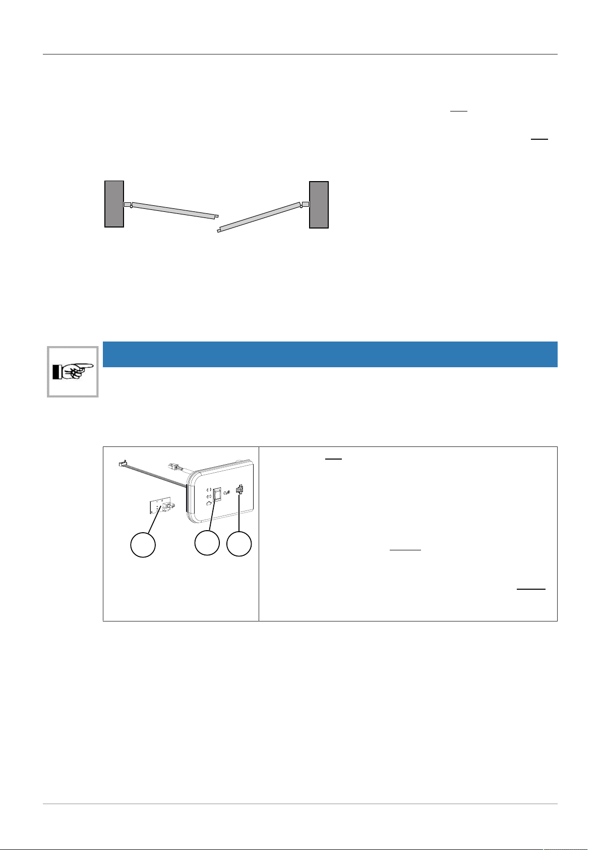
3.6 Control panel
3
12
7
Toggle switch BDI (2) on the side cover of the operator with three
operation modes to choose from.
– Automatic
– Continuously open
– Manual operation
The connection for service (3) is found at the side cover.
If an electronic control panel BDE-D is connected, this has priority
for operation.
If a mechanical control panel BDE-M or an external activation is
used, the toggle switch BDI must be replaced with option BDI-M
(1).
Control elements and displays [}16]
3Description
14 / 28 BAL_DFA_127_EN_1V0_OEM_102-127401806
1
2
4 5 6 7 8910
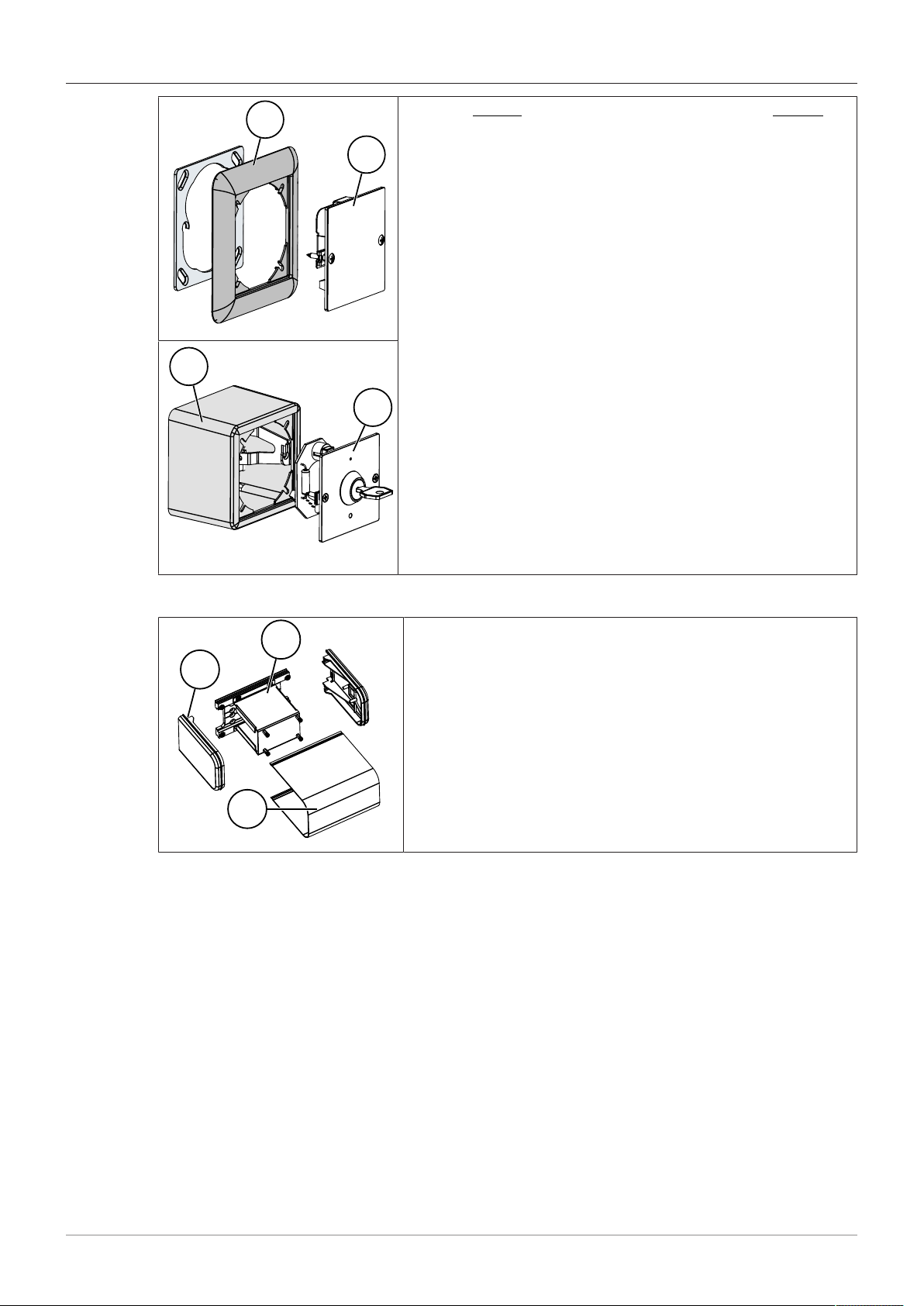
Electronic BDE-D (2) and/or mechanical control panel BDE-M (4).
The electronic control panel can be used to choose between five
operation modes and set selected door parameters.
– Automatic
– Continuously open
– One-way
– Manual operation
– Locked
The control panels can be installed with corresponding attach-
ments as a flush-mounted (1) or surface-mounted (3) version.
Control panel BDE-D [}16]
3
4
5 6 7 8910
3.7 Battery pack (optional)
1
3
2
The battery pack supplies power to the operator in the event of a
power failure. It is installed on the side of the operator and con-
sists of a side cover (1), battery kit (2), and casing (3).
If space allows, the battery kit (2) can be installed in the operator
housing.

Specifications 4
BAL_DFA_127_EN_1V0_OEM_102-127401806 15 / 28
4 Specifications
4.1 Tecnical data
Operating voltage: 230VAC, 50/60 Hz
Power consumption: Standby 13 W, rated power 67 W
Max. torque: 50 Nm
Max. Mass inertia door leaf: 65 kgm2
Opening angle: 70° - 115°
Hold open time 0 to 60 seconds (40 steps)
Opening speed: 3 to 20 seconds (40 steps)
Closing speed: 5 to 20 seconds (40 steps)
Noise generation: < 45 dB
Degree of protection: IP20
Temperature range: From -15 to +50° C
Humidity range: Up to 85% rel. humidity, not condensing
5Operation
16 / 28 BAL_DFA_127_EN_1V0_OEM_102-127401806
5 Operation
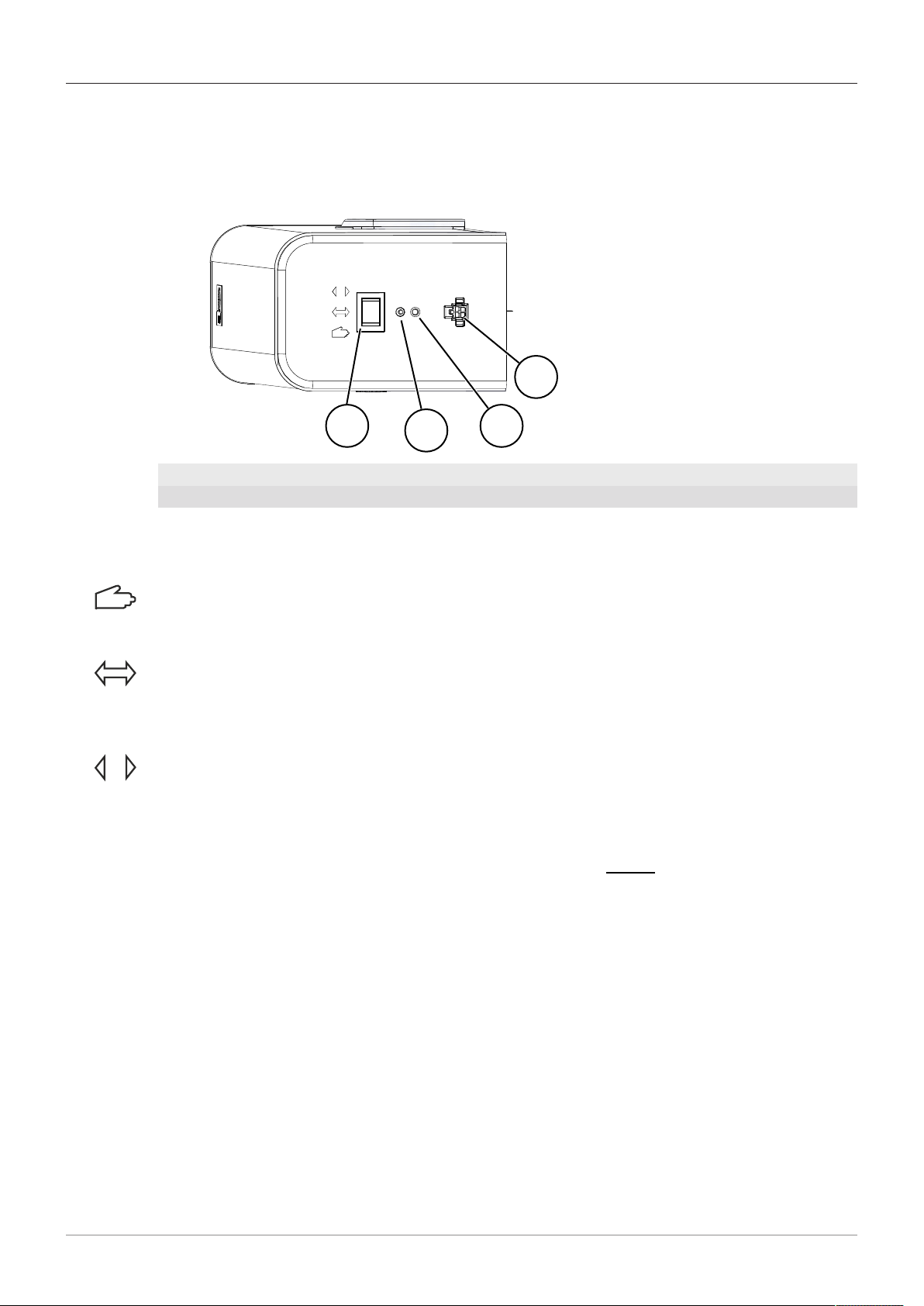
5.1 Toggle switch BDI
5.1.1 Control elements and displays
123
4
1 Toggle switch BDI 2 Reset button
3 Status display LED 4 Connection for configuration tool
Toggle switch BDI
Three operation modes can be selected using the toggle switch:
Manual operation:
The operator works like a door closer. It can be opened manually and closes independently. The
connected sensors are disabled.
Automatic:
In the "Automatic" operation mode, the door opens with the aid of a trigger device/sensor or when
pushed when the touch control is activated. The door closes after the hold open time has elapsed,
unless a new opening impulse is given.
Continuously open:
The door remains open.
If the door encounters an obstacle when opening, the operator attempts to open the door. If the
obstacle does not move, the current position is recognized as continuously open.
The toggle switch is always active. If an electronic control panel BDE-D is connected, the operation
mode is determined by this.
Reset button
When pressed for 5 seconds, this button resets the control device.
Status display LED
– When LED is off the operator is ready to use.
– Flashes when an error occurs during operation.
5.2 Control panel BDE-D
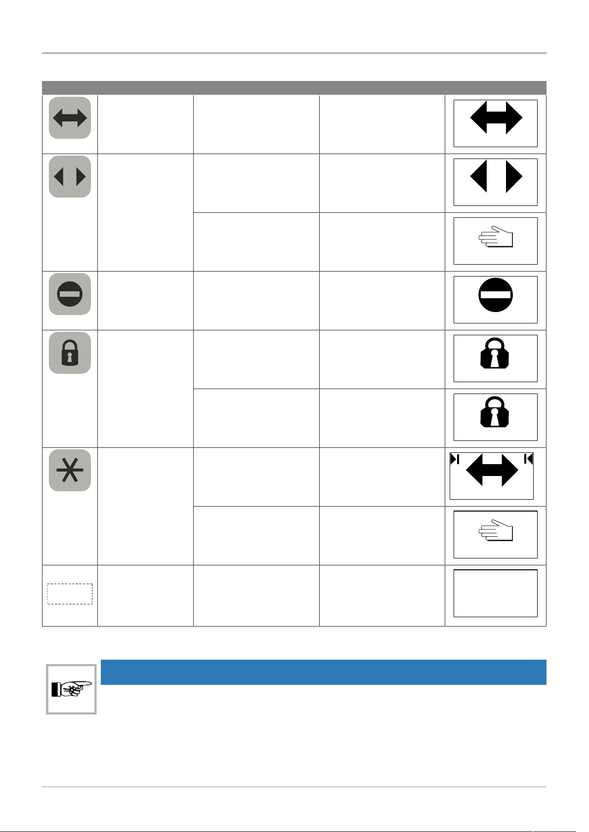
5.2.1 Operation modes and button functions
The buttons on the control panel BDE-D are used to set the door system operation modes in the main
menu. The parameters of the door system are set in the sub menu.
The button functions are divided into main menu and sub menu.
Operation 5
BAL_DFA_127_EN_1V0_OEM_102-127401806 17 / 28
Main menu
Button Name Operation Function Display on LCD
Automatic button Press button 1 x Automatic operation via
sensors
Automatic
Continuously open
button
Press button 1 x For sliding door operator
and swing door operator:
continuously open, sensors
disabled
Continuously open
Press button 2 x or hold it
down for 2 seconds
For sliding door operator:
manual operation
Manual
One-way button Press button 1 x Passage only possible from
one direction
One-way
Locking button Press button 1 x Door closed, sensors dis-
abled
Locked
Press button again The door opens again,
closes, and locks again.
Can be opened with a key
(optional).
Locked
Star button Press button 1 x For sliding door operator:
Reduced open width
Automatic
Press button 1 x For swing door operator:
manual operation
Manual
E
Menu button Restart control device:
press button for 5 seconds
Restart hardware BDE-D:
press button for 12 seconds
Access to parameter menu
Enable control lock
Restart control device
Restart hardware BDE-D
Sub menu
NOTICE
The main menu is returned to automatically 3 minutes after the last entry.

5Operation
18 / 28 BAL_DFA_127_EN_1V0_OEM_102-127401806
Button Name Operation Function Display on LCD
E
Enter button Press button 1 x to go to
the next sub menu.
Select menu item, confirm
entry
Opening speed
0 10 20 30 40
+
Plus button Press button 1 x to go
down.
Navigate downwards in the
menu
Parameter
Driving cycle
Time delay open
Operator
Press button 1 x to increase
the value.
Move the slide control to
the right to increase the
value
Closing speed
0 10 20 30 40
-
Minus button Press button 1 x to go up. Navigate upwards in the
menu
Parameter
Driving cycle
Time delay open
Operator
Press button 1 x to reduce
the value.
Move the slide control to
the left to reduce the value
Closing speed
0 10 20 30 40
C
Clear button Press button 1 x to go to
the previous menu.
Leave the menu item
without saving.
Parameter
Driving cycle
Time delay open
Operator
5.2.2 Perform reset
Reset controller
Step Button Operation Function Display on LCD
1.
E
Press button for 5 seconds Perform controller reset
No
Reset controller?
Yes
2.
C
Press button 1 x Cancel reset
E
Press button 1 x Perform reset
Reset control panel
Step Button Operation Function Display on LCD
1.
E
Press button for 12 seconds Perform control panel reset

Operation 5
BAL_DFA_127_EN_1V0_OEM_102-127401806 19 / 28
Step Button Operation Function Display on LCD
2.
3. The connection has been established
DFA 127 V2.21
Basic operator
5.2.3 Display system information
Information about the door system, such as software version, door type, or servicing status, can be
shown on the display.
NOTICE
The main view is returned to by scrolling or automatically after 20 seconds.
Step Button Operation Function
1.
E
Press button for approx.
2 seconds
Software information
is displayed
STA20 V2.0
BDE-D V2.05 1
Software
2.
E
Press button 1 x Scroll through the in-
formation and/or re-
turn to main view
STA20 V2.0
BDE-D V2.05 1
Software
3.
E
Press button 1 x Scroll through the in-
formation and/or re-
turn to main view
Servicing
0 50 100
5.2.4 Lock control panel
Enable control lock on the keyboard
Step Button Operation Function Display on LCD
1.
E
Press the button se-
quence as shown
To disable, press the
button sequence again
No settings can be made
on the control panel BDE-
D.
Automatic
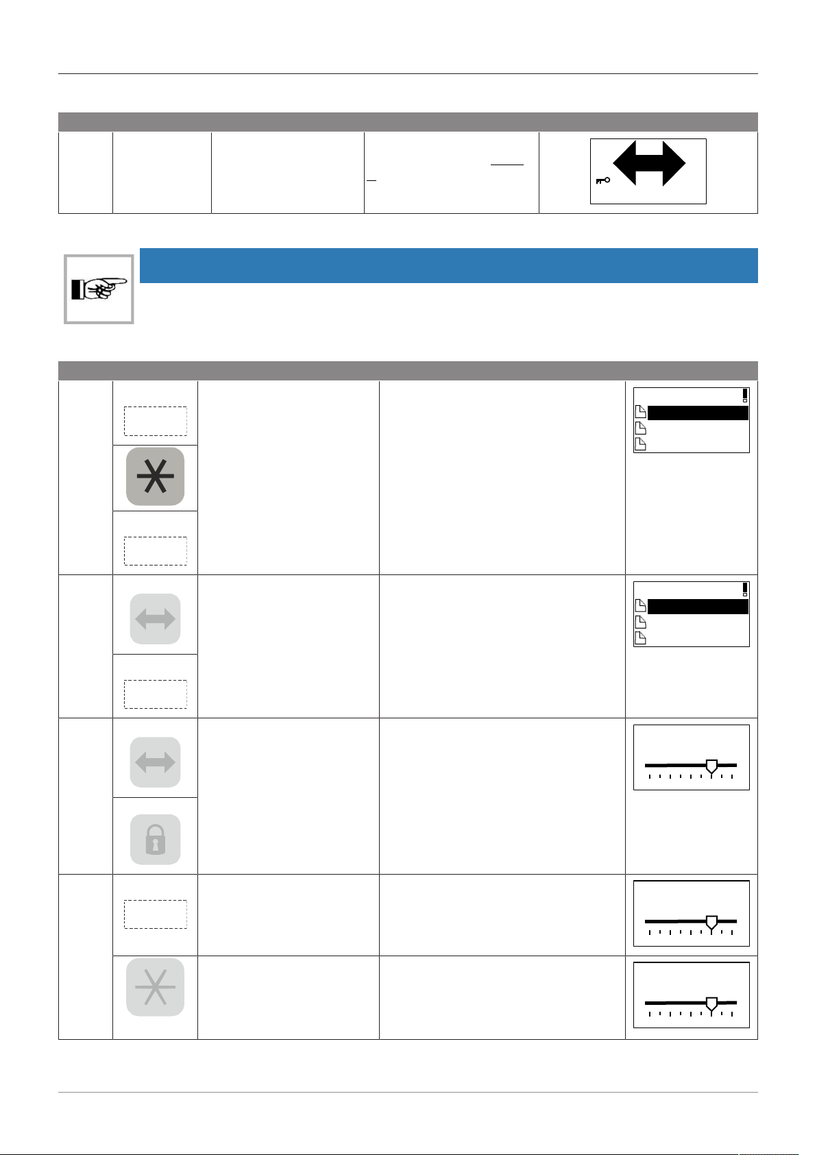
5Operation
20 / 28 BAL_DFA_127_EN_1V0_OEM_102-127401806
Enable control lock with key
Step Requirement Operation Function Display on LCD
1. The desired
operation
mode is set.
Enable/disable the con-
trol lock with the key
No settings can be made
on the control panel BDE-
D.
Automatic
5.2.5 Set parameters
IMPORTANT
With the type "low energy", the parameters can only be changed by qualified personnel.
The following example of the closing speed explains how to set the parameters of the door.
Step Button Operation Function Display on LCD
1.
E
Press the buttons in the or-
der shown
Access to the parameters in the sub
menu
Parameter
Driving cycle
Time delay open
Operator
E
2.
+
Press the buttons in the or-
der shown
In the sub menu, access the parameter
closing speed
Driving cycle
Closing speed
Opening speed
Acceleration
E
3.
+
Set the closing speed with
the buttons shown.
Hold down the button to
move continuously
Increase speed
0 = minimum speed
40 = maximum speed
Closing speed
0 10 20 30 40
-
6.
E
Press button 1 x Save value
Closing speed
0 10 20 30 40
C
Press button 1 x Leave without saving
Closing speed
0 10 20 30 40
Table of contents
Popular Door Opening System manuals by other brands

Dormakaba
Dormakaba PT 22 Installation instruction

FAAC
FAAC A1000 user manual

Cal-Royal
Cal-Royal CR3049HOSPRS installation instructions

Lamp
Lamp AZ-GD231 installation instructions

GEZE
GEZE Slimdrive SL NT Installation and service instructions

Assa Abloy
Assa Abloy Corbin Russwin ED4000 Series installation instructions


hager
hager 5200 Series installation instructions

CornellCookson
CornellCookson FS-36EP Series Installation instructions and operation manual

Dormakaba
Dormakaba RTS Series installation instructions

Automatic Technology
Automatic Technology HiRO GDO-12 Wiring and Installation Instructions

Command access
Command access MLRK1 Series instructions

Kason
Kason 10058E Series installation instructions