manuals.online logo
Brands
  1. Home
  2. •
  3. Brands
  4. •
  5. Cal-Royal
  6. •
  7. Door Opening System
  8. •
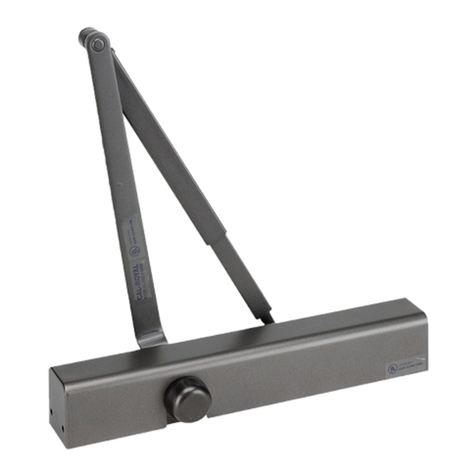
  9. Cal-Royal CR3049HOSPRS User manual

Cal-Royal CR3049HOSPRS User manual

CR3049HOSPRS & CR3077SPAS
INSTALLATION INSTRUCTIONS
PUSH SIDE MOUNTED(PARALLEL ARM)
HOW TO DETERMINE
HAND OF DOOR
RIGHT
HAND
DOOR
LEFT
HAND
DOOR
CLOSER CONTROL DIAGRAM
BACK CHECK
MAIN SPEED
LATCH
SPEED
DECREASE
SPRING
POWER
C.C.W.
MAXIMUM DOOR
WIDTH FULL
TURNS
REQUIRED
EXTERIO
R DOORS
EXTERIOR
DOORS
-------- 5 lb-f* 5 TURNS C.C.W.
8.5 lb-f* 34"(864) 2 TURNS C.C.W.
30" (762) 38"(962) 0 TURNS
36"(914) 48"(1219) 5 TURNS C.W.
42"(1067) 54"(1372) 10 TURNS C.W.
48"(1219) 60"(1524) 15 TURNS C.W.
INSTALL ON DROP PLATE
(FOR NARROW RAIN INSTALLATION)
STANDARD INSTALLATION
GENERAL NOTES
The Cushion Arm Closer is non-handed and is designed to meet entrance
accessibility requirements. Determine hand of door first before installation.
Refer to illustration (right), then the proper installation template.
The Cushion Arm Closer can be adjusted to handle all exterior doors up to
4'0" and interior doors up to 5'0" wide. Adjust the spring power as shown
before installing the closer. Turn the spring adjustment nut clockwise or
counter-clockwise to the required number of turns to match door width as
indicated in the chart below.
ALLEN
WRENCH
INCREASE
SPRING
POWER
C.W.
IMPORTANT - When adjusting spring power DO NOT exceed the
maximum number of turns in either direction. Doing so may damage the closer
* Opening force on 36" Door
DWG # DCG1020 - 1/3 - APR2022
FOR TOP RAIL LESS THAN 5-1/2”, DROP PLATE WILL BE REQUIRED
MAXIMUM OPENING 110° PUSH SIDE MOUNTING
3-38"
(86)
2-18"
(54)
1116"(17.5)
516"(8)
DOOR
STOP
2-38"(60)
3-316"(81)
5-12"(140)
11-18"(283) = 85º
10-12"(267) = 90º
9-14"(235) = 100º
8-38"(213) = 110º
HINGE CENTER
SCREWS FOR SHOE PA BRACKET
1/4-20x 58 P.H.M.S (4) OR ST6.3x35 P.H.W.S (4)
1/4-20x 1-12" P.H.M.S (1) OR ST6.3x50 P.H.W.S (1)
2-14"(57)
2-316"(56)
HINGE CENTER
STOP FACE
SCREWS FOR CLOSER
14 - 20 x 2-1/4 P.H.M.S(4) OR ST6. 3 x75 P.H.W.S (4)
COVER
LEFT HAND
2-14"(57)
2-316"(56)
HINGE CENTER
STOP FACE
RIGHT HAND
IMPORTANT: USE SPACER BLOCK PROVIDED FOR
FIFTH SCREW
MOUNTED STOP FACE (PUSH SIDE) PARALLEL ARM
(AVAILABLE FROM DEALER)
3-38"
(86)
2-18"
(54)
1116"
(17.5)
516"
(8)
DOOR
STOP
2-38"(60)
3-316"(83.5)
5-12"(140)
HINGE CENTER
1"
(25.5)
1'
(25.5)
3"
(76)
1"
(25.5)
3"
(76)
1"
(25.5)
BEFORE INSTALLING MOUNTED STOP FACE (PARALLEL ARM) TURN BACKCHECK SELECTOR VALVE
(FOUND ON OPPOSITE SIDE OF CLOSER FROM REGULATING SCREW SIDE) ALL THE WAY IN (CLOCKWISE)!
3-38"
(86)
2-18"
(54)
1116"
(17.5)
516"(8)
DOOR
STOP
2-38"(60)
3-316"(81)
5-12"(140)
11-18"(283) = 85º
10-12"(267) = 90º
9-14"(235) = 100º
8-38"(213) = 110º
HINGE CENTER
SCREWS FOR SHOE PA BRACKET
1/4-20 x 58 P.H.M.S (4) OR ST6.3x35 P.H.W.S (4)
1/4-20 x 1-12" P.H.M.S (1) OR ST6.3x50 P.H.W.S (1)
HINGE CENTER
STOP FACE
SCREWS FOR CLOSER
14 - 20 x 24 P.H.M.S(4)
DROP PLATE
LEFT HAND HAND SHOWN. RIGHT HAND OPPOSITE
8-38"(213) = 85º
7-58"(194) = 90º
6-12"(165) = 100º
5-12"(140) = 110º
1-12"
(38)
8-14"
(210)
1-12"
(38)
1116"(17.5)
1516"(24)
SCREWS FOR CLOSER
14 - 20 x 5
8" P.H.M.S(4) OR
ST6.3 X 35 P.H.W.S(4)
MIN 2-12"(64)
IMPORTANT:
USE SPACER BLOCK PROVIDED FOR
FIFTH SCREW
ON DROP PLATE
9-12"(241) = 85º
8-34"(222) = 90º
7-58"(194) = 100º
6-58"(168) = 110º
9-12"(241) = 85º
8-34"(222) = 90º
7-58"(194) = 100º
6-58"(168) = 110º
11-18"(283) = 85º
10-12"(267) = 90º
9-14"(235) = 100º
8-38"(213) = 110º
DWG # DCG1020 - 2/3 - APR2022
5/16 OR 8mm
HEX WRENCh
Both D.S. / DSHO shoes must be " handed" to
match door BEFORE mounting. see Fig. 1
For Left Hand doors: All shoes are shipped assembled
for left hand doors. Insert 516" (8mm) Hex wrench into
arm stop and turn counter - clockwise to seat stop as
tightly as possible.
INSTALLATION & ADJUSTMENT INSTRUCTIONS
(LEFT HAND SHOWN - RIGHT HAND OPPOSITE)
REGULATION
The BA series closer has been regulated prior to shipment.
If adjustment are necessary, carefully follow instructions.
CLOSING SPEED: See Closer Control Diagram on page 1.
To adjust Main Speed, turn reg. screw clockwise to decrease
or counter-clockwise to increase. To adjust Latch Speed,
turn reg.screw clockwise to decrease or counter-clockwise to
increase. Reg.screw locations are shown at left and on label
BACKCHECK: is essential to proper operation of Cush-Stop.
Use enough backcheck to prevent arm from striking arm stop
with impact. To increase resistance. Turn reg. screw clockwise.
- DO NOT USE ABRUPT BACKCHECK! -
6. Attach cover: place cover insert into proper slots for
either R.H. or L.H. door. Place cover over closer and hold
against door while tightening cover screws firmly
BRACKET
ARM STOP
FILLER PLUG
CAUTION
IMPROPER INSTALLATION OR REGULATION
MAY RESULT IN PERSONAL INJURY OR
PROPERTY DAMAGE
FOLLOW ALL INSTRUCTION CAREFULLY.
FOR QUESTION CONTACT DEALER
OPTIONAL
DROP PLATE
REMOVABLE INSERTS
TO CONVERT TO OPPOSITE
HAND COVER
SELECTOR VALVE SCREW
SIZE ADJUST
BACKCHECK SCREW
MAIN ARM
ARM
SCREW
COVER
SCREW
MAIN SPEED
SCREW
LATCH SPEED
SCREW
30º APPROX.
RIGHT HAND ASSEMBLY SHOW
HANDING & ASSEMBLY OF D.S./ DSHO SHOE
For Right Hand doors: (see illustration) Push filler plug
out of shoe. Using a 516" (8mm) Hex wrench, turn arm in
hole marked "R". Turn wrench counter-clockwise, seating
stop as tightly as possible. Insert filler plug into other hole.
1. Adjust spring power to match door width as indicated
by chart on front page.
2. Select proper templating on opposite page, based on
degree on openning/dead stop. The closer and arm holes
must be located for same degree of openning/dead
stop. Drill and/ or tap mounting holes in door and
head jamb.
3. Attach complete arm to closer, as shown at left.
Arm will be at about a 30º angle to closer body.
Fasten with arm shaft screw. The arm will appear to
be in an incorrect position. This is to accommodate the
pre-load required for parallel arm mounted door
closer. See Fig.2.
4. Mount closer on door, using fasteners provided.
NOTE: arm will provide some resistance.
5. Swing door open about 45º. Mount shoe to frame stop
per proper templating on opposite page. Be sure to
install the "fifth" screw. If stop is not wide enough,
use spacer block provided.
BEFORE INSTALLING THE ARM - TURN BACKCHECK
SELECTOR VALVE (on back of closer) ALL THE WAY IN.
CAUTION DO NOT BACK VALVES OUT OF
CLOSER OR A LEAK WILL RESULT
DWG # DCG1020 - 3/3 - APR2022

This manual suits for next models

1

Other Cal-Royal Door Opening System manuals

Cal-Royal 2260V Series User manual

Cal-Royal

Cal-Royal 2260V Series User manual

Cal-Royal N-FMR7700 Series User manual

Cal-Royal

Cal-Royal N-FMR7700 Series User manual

Cal-Royal 7760V Series User manual

Cal-Royal

Cal-Royal 7760V Series User manual

Cal-Royal 8600 User manual

Cal-Royal

Cal-Royal 8600 User manual

Cal-Royal 500 Series Instruction sheet

Cal-Royal

Cal-Royal 500 Series Instruction sheet

Cal-Royal 801 Series User manual

Cal-Royal

Cal-Royal 801 Series User manual

Cal-Royal 98-3PT User manual

Cal-Royal

Cal-Royal 98-3PT User manual

Cal-Royal N-F98CVR User manual

Cal-Royal

Cal-Royal N-F98CVR User manual

Cal-Royal A2260V Series User manual

Cal-Royal

Cal-Royal A2260V Series User manual

Cal-Royal 8600 User manual

Cal-Royal

Cal-Royal 8600 User manual

Cal-Royal N-77CVR User manual

Cal-Royal

Cal-Royal N-77CVR User manual

Cal-Royal 22-3PT User manual

Cal-Royal

Cal-Royal 22-3PT User manual

Cal-Royal N-F77CVR User manual

Cal-Royal

Cal-Royal N-F77CVR User manual

Cal-Royal 900 Series User manual

Cal-Royal

Cal-Royal 900 Series User manual

Cal-Royal N900 Series User manual

Cal-Royal

Cal-Royal N900 Series User manual

Cal-Royal N-MR7700 Series User manual

Cal-Royal

Cal-Royal N-MR7700 Series User manual

Cal-Royal CR801 Series User manual

Cal-Royal

Cal-Royal CR801 Series User manual

Cal-Royal N-CVRESC User manual

Cal-Royal

Cal-Royal N-CVRESC User manual

Popular Door Opening System manuals by other brands

Dorma G-SR EMR Fixing instructions

Dorma

Dorma G-SR EMR Fixing instructions

FAAC XKPR125D manual

FAAC

FAAC XKPR125D manual

Hettich TopLine 22 installation instructions

Hettich

Hettich TopLine 22 installation instructions

GAL MOVFR installation instructions

GAL

GAL MOVFR installation instructions

Altronix TROVE T1KE34DV installation guide

Altronix

Altronix TROVE T1KE34DV installation guide

Assa Abloy 1370 Mounting instructions

Assa Abloy

Assa Abloy 1370 Mounting instructions

Helm MK-L 80 G 120 installation instructions

Helm

Helm MK-L 80 G 120 installation instructions

Mantion SLID'UP 2500 Instructions for assembly

Mantion

Mantion SLID'UP 2500 Instructions for assembly

RollSeal RS-500M Installation and operation manual

RollSeal

RollSeal RS-500M Installation and operation manual

BEA ZENSAFE manual

BEA

BEA ZENSAFE manual

Stanley Dura-Glide Series Owner's operation and maintenance manual

Stanley

Stanley Dura-Glide Series Owner's operation and maintenance manual

CDVI IPV1 manual

CDVI

CDVI IPV1 manual

SUGATSUNE LAMP FD50-H installation manual

SUGATSUNE

SUGATSUNE LAMP FD50-H installation manual

GFA VR/TF2E instructions

GFA

GFA VR/TF2E instructions

Besam PowerSwing manual

Besam

Besam PowerSwing manual

D+H BAZ 04-N-UT Original instructions

D+H

D+H BAZ 04-N-UT Original instructions

DITEC DAS900FM installation manual

DITEC

DITEC DAS900FM installation manual

Gliderol IGDU GEN II Upgrade Kit Install & user's guide

Gliderol

Gliderol IGDU GEN II Upgrade Kit Install & user's guide

manuals.online logo
manuals.online logoBrands
  • About & Mission
  • Contact us
  • Privacy Policy
  • Terms and Conditions

Copyright 2025 Manuals.Online. All Rights Reserved.