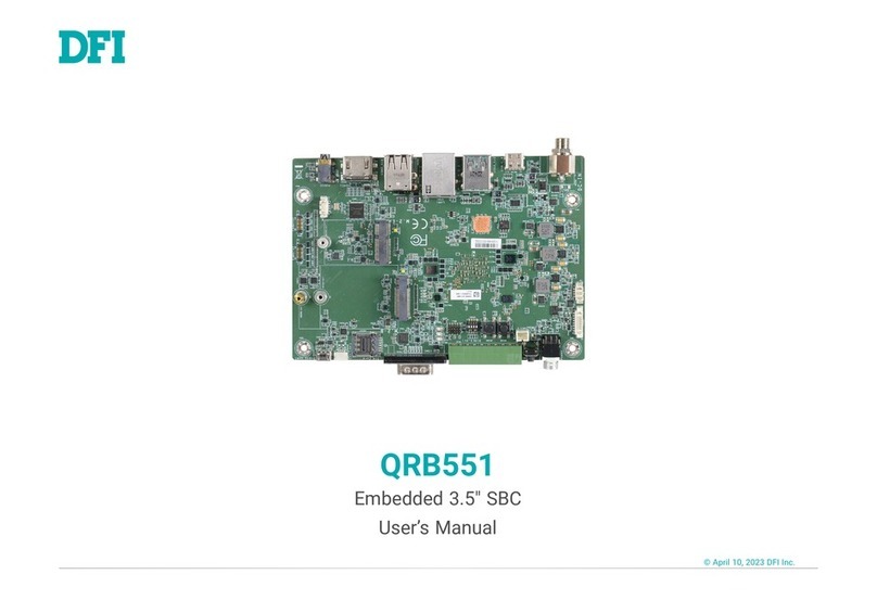
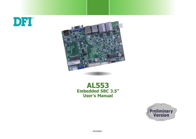
DFI CL60-LX User manual

CL60-LX
Rev. A+
System Board
Carte Mère Manuel
System-Platine
Users Manual
Pour Utilisateur
Benutzerhandbuch
37700902
All manuals and user guides at all-guides.com
all-guides.com

Copyright
This publication contains information that is protected by copyright. No part of it may
be reproduced in any form or by any means or used to make any transformation/
adaptation without the prior written permission from the copyright holders.
This publication is provided for informational purposes only. The manufacturer makes
no representations or warranties with respect to the contents or use of this manual and
specifically disclaims any express or implied warranties of merchantability or fitness
for any particular purpose.The user will assume the entire risk of the use or the results
of the use of this document. Further, the manufacturer reserves the right to revise this
publication and make changes to its contents at any time, without obligation to notify
any person or entity of such revisions or changes.
© 1999. All Rights Reserved.
Trademarks
Microsoft®MS-DOS®, WindowsTM, Windows®95 and Windows®98 are registered
trademarks of Microsoft Corporation. Intel®, Pentium®II and CeleronTM are registered
trademarks of Intel Corporation. Award is a registered trademark of Award Software,
Inc. Other trademarks and registered trademarks of products appearing in this manual
are the properties of their respective holders.
Caution:
Danger of explosion if battery incorrectly replaced.
Replace only with the same or equivalent type recommended by the
manufacturer.
Dispose of used batteries according to the battery manufacturers instructions.
FCC and DOC Statement on Class B
This equipment has been tested and found to comply with the limits for a Class
B digital device, pursuant to Part 15 of the FCC rules. These limits are designed
to provide reasonable protection against harmful interference when the
equipment is operated in a residential installation. This equipment generates, uses
and can radiate radio frequency energy and, if not installed and used in
accordance with the instruction manual, may cause harmful interference to radio
communications. However, there is no guarantee that interference will not occur
in a particular installation. If this equipment does cause harmful interference to
radio or television reception, which can be determined by turning the equipment
off and on, the user is encouraged to try to correct the interference by one or
more of the following measures:
Reorient or relocate the receiving antenna.
Increase the separation between the equipment and the receiver.
Connect the equipment into an outlet on a circuit different from that to
which the receiver is connected.
Consult the dealer or an experienced radio TV technician for help.
Notice:
1. The changes or modifications not expressly approved by the party
responsible for compliance could void the user's authority to operate the
equipment.
2. Shielded interface cables must be used in order to comply with the emission
limits.
All manuals and user guides at all-guides.com

Table of Contents / Sommaire / Inhaltsverzeichnis
4
7
18
19
20
21
22
23
24
26
27
31
31
35
8
9
10
11
12
37
38
38
Chapter 1 - Introduction
1.1 Features and Specifications...................................................................
1.2 Package Checklist ......................................................................................
Chapter 2 - Hardware Installation
2.1 System Board Layout ..............................................................................
2.2 DIP Switch Settings of the Processors .........................................
2.3 Jumper Settings for Clearing CMOS Data.................................
2.4 Jumper Settings for Wake-On-Keyboard/Mouse.....................
2.5 Connectors ....................................................................................................
Chapter 3 - Award BIOS Setup Utility
3.1 Entering the Award BIOS Setup Utility ........................................
3.2 Setting the Date and Time...................................................................
3.3 Selecting the Hard Drive and Floppy Drive Type...................
3.4 Selecting the Drive to be Searched First for an
Operating System ......................................................................................
3.5 Selecting the External System Bus Clock of the Processor
3.6 Selecting an IRQ for the External Modem .................................
3.7 Selecting the Method of Powering-off the System .................
3.8 Selecting the Power Lost Resume State ......................................
3.9 Using the System Health Monitor Function ...............................
3.10 Loading Fail-Safe Settings/Optimal Settings ...............................
3.11 Setting the Wake-On-Keyboard/Mouse Function ...................
3.12 Setting the Supervisor/User Password .........................................
Chapter 4 - Supported Softwares
4.1 Utility ................................................................................................................
Appendix A - System Error Messages
A.1 POST Beep ...................................................................................................
A.2 Error Messages ............................................................................................
Note:
The users manual in the provided CD contains detailed information
about the system board. If, in some cases, some information doesnt
match those shown in this manual, this manual should always be
regarded as the most updated version. To view the users manual,
insert the CD into a CD-ROM drive. The autorun screen (Main Board
Utility CD) will appear. Click Users Manual.
All manuals and user guides at all-guides.com

4
1.1 Features and Specifications
Caractéristiques et Spécifications
Leistungsmerkmale und Technische Daten
1.1.1 Features / Caractéristiques / Leistungsmerkmale
Chipset
Intel440LX AGPset
Processor
The system board is equipped with IntelSocket 370 and a
switching voltage regulator that automatically detects 1.30V to
2.05V.
300A/333/366/400/433MHz CeleronTM PPGA processor
System Memory
16MB to 384MB memory using unbuffered DIMMs
Three 168-pin DIMM sockets
Uses SDRAM (10/12/13ns), 3.3V
ECC supported (uses x72 SDRAM)
Expansion Slots
The system board is equipped with 1 dedicated AGP slot, 3
dedicated PCI slots, 2 dedicated 16-bit ISA slot and 1 shared PCI/
ISA slot. All PCI and ISA slots are bus masters.
Desktop Management Interface (DMI)
The system board comes with a DMI 2.0 built into the BIOS. The
DMI utility in the BIOS automatically records various information
about your system configuration and stores these information in the
DMI pool, which is a part of the system board's Plug and Play
BIOS. DMI, along with the appropriately networked software, is
designed to make inventory, maintenance and troubleshooting of
computer systems easier.
Chapter 1 - Introduction / Introduction / Einleitung
DIMMs
2MBx64/x72
4MBx64/x72
Memory Size
16MB
32MB
DIMMs
8MBx64/x72
16MBx64/x72
Memory Size
64MB
128MB
All manuals and user guides at all-guides.com

1
Introduction
5
ATX Double Deck Ports
2 USB ports
Two NS16C550A-compatible DB-9 serial ports
One SPP/ECP/EPP DB-25 parallel port
One mini-DIN-6 PS/2 mouse port
One mini-DIN-6 PS/2 keyboard port
Connectors
One connector for IrDA interface
Two IDE connectors
One floppy drive interface supports up to two 2.88MB floppy
drives
One 20-pin ATX power supply connector
One 3-pin WOL (Wake-On-LAN) connector
One SB-LINK connector
Three fan connectors for CPU, chassis and AGP fans.
PCI Bus Master IDE Controller
Two PCI IDE interfaces support up to four IDE devices
Ultra DMA/33 supported (Synchronous Ultra DMA mode -
data transfer rate up to a maximum of 33MB/sec.)
PIO Mode 3 and Mode 4 Enhanced IDE (data transfer rate up
to 16.6MB/sec.)
Bus mastering reduces CPU utilization during disk transfer
ATAPI CD-ROM, LS-120 and ZIP supported
IrDA Interface
The system board is equipped with an IrDA connector for wireless
connectivity between your computer and peripheral devices. It
supports peripheral devices that meet the IrDA or ASKIR standard.
USB Ports
The system board is equipped with two USB ports. USB allows
data exchange between your computer and a wide range of
simultaneously accessible external Plug and Play peripherals.
BIOS
Award BIOS, Windows95 Plug and Play compatible
Flash EPROM for easy BIOS upgrades
All manuals and user guides at all-guides.com

Introduction
1
6
1.1.2 System Health Monitor Functions
System Health Monitor Fonctions
System Health Monitor Funktions
The system board is capable of monitoring the following system
health conditions.
Monitors processor/system temperature and processor overheat
alarm
Monitors 1.5V/3.3V/±5V/±12V/VCORE voltages and failure
alarm
Monitors processor/chassis fan speed and failure alarm
Automatic processor/chassis fan control
Read back capability that displays accurate temperature, voltage
and fan speed
1.1.3 Intelligence / Intelligence / Intelligente Ausstattungsteile
Automatic CPU/Chassis Fan Off
The CPU and chassis fans will automatically turn off once the system
enters the Suspend mode.
Dual Function Power Button
Depending on the setting in the BIOS setup, this switch will allow
your system to enter the Soft-Off or Suspend mode.
External Modem Ring-on
The Modem Ring-on feature allows the system that is in the
Suspend mode or Soft Power Off mode to wake-up/power-on to
respond to incoming calls. This feature supports external modem
only.
RTC Timer to Power-On the System
The RTC installed on the system board allows your system to
automatically power-on on the set date and time.
Wake-On-LAN Ready
The Wake-On-LAN function allows the network to remotely wake
up a Soft Power Down (Soft-Off) PC.Your LAN card must support
the remote wakeup function.
Important:
The 5VSB power source of your power supply must support
≥720mA (minimum).
Wake-On-Keyboard/Wake-On-Mouse
This function allows you to use the keyboard or mouse to power-on
the system. Refer to sections 2.4 (chapter 2) and 3.11 (chapter 3)
for more information.
All manuals and user guides at all-guides.com
all-guides.com

1
Introduction
7
Important:
The power button will not function once a keyboard
password has been set in the KB Power On Password
field of the Integrated Peripherals setup. You must type the
correct password to power-on the system.
The 5VSB power source of your power supply must
support ≥720mA (minimum).
ACPI
The system board is designed to meet the ACPI (Advanced
Configuration and Power Interface) specification. ACPI has energy
saving features that enables PCs to implement Power Management
and Plug-and-Play with operating systems that support OS Direct
Power Management.
Virus Protection
Most viruses today destroy data stored in hard drives. The system
board is designed to protect the boot sector and partition table of
your hard disk drive.
1.2 Package Checklist
Liste de Vérification de lEmballage
Verpackungsliste
The system board package contains the following items:
þThe system board
þA users manual
þOne 40-pin IDE hard disk cable
þOne 34-pin floppy disk drive cable
þOne CD
If any of these items are missing or damaged, please contact your
dealer or sales representative for assistance.
All manuals and user guides at all-guides.com

8
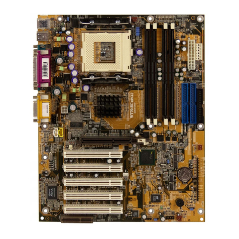
2.1 System Board Layout
Position de la Carte Système
Aufbau der Hauptplatine
Chapter 2 - Hardware Installation
Installation du Matériel
Installation der Hardware
All manuals and user guides at all-guides.com

2
Hardware Installation
9
2.2 DIP Switch Settings for Processors
Positionnement des Cavaliers des Processeurs
DIP Schaltereinstellungen für den Prozessor
Note:
SW1 is for factory use only.
Note:
1. Intel CeleronTM PPGA processors support VID (Voltage Identification).
The switching voltage regulator on the system board will automatically
set the voltage regulator according to the voltage of the processor.
2. You cannot overclock an Intel CeleronTM PPGA processor because its
frequency ratio has been fixed by the manufacturer. The table above is
for factory use only.
In the example above:
Switch 1: Off
Switch 2: On
Switch 3: Off
Switch 4: On
300MHz 4.5x
333MHz 5x
SW1
Frequency
Ratio
5.5x
SW1
Frequency
Ratio
400MHz
433MHz
Future
processor
Future
processor
6x
6.5x
7x
7.5x
8x
Future
processor
366MHz
66MHz
CPU
Frequency Ext. System
Bus Clock
66MHz
66MHz
66MHz
Ext. System
Bus Clock
CPU
Frequency
66MHz
66MHz
66MHz
66MHz
All manuals and user guides at all-guides.com

2
10
Hardware Installation
2.3 Jumper Settings for Clearing CMOS Data
Positionnement des Cavaliers pour Effacer les Données
CMOS
Jumpereinstellungen zum Löschen der CMOS Daten
Jumper JP2 - Clear CMOS Data
To load the default values stored in
the ROM BIOS, please follow the
steps below.
1. Power-off the system and unplug
the power cord.
2. Set JP2 pins 2 and 3 to On.
Wait for a few seconds and set
JP2 back to its default setting,
pins 1 and 2 On.
3. Plug the power cord and power-
on the system.
2-3 On:
Clear CMOS Data
1-2 On: Normal
(default)
1
2
3
1
2
3
All manuals and user guides at all-guides.com

2
Hardware Installation
11
2.4 Jumper Settings for Wake-On-Keyboard/Mouse
Positionnement des Cavaliers pour Réveil-Sur-Clavier/
Souris
Jumpereinstellungen für die Wake-On Tastatur/Maus
Jumper JP1 - Wake-on-Keyboard/Wake-On-Mouse
To use the keyboard or mouse to power-on the system, please
follow the steps below.
1. Set JP1 to 2-3 On - enable.
2 Keyboard/Mouse Power On in the
Integrated Peripherals setup of the
Award BIOS must be set
accordingly. Refer to section 3.11
(chapter 3) for more information.
Warning:
1. If JP1 was previously enabled
with a password set in the KB
Power On Password field, and
now you wish to disable the
Wake-On-Keyboard
(password) function, make sure
to set the Keyboard/Mouse
Power On field to Disabled
prior to setting JP1 to disabled.
You will not be able to boot up the system if you fail to do so.
2. The power button will not function once a keyboard
password has been set in the KB Power On Password
field of the Integrated Peripherals setup. You must type the
correct password to power-on the system.
3. The 5VSB power source of your power supply must
support
≥
720mA (minimum).
2-3 On: Enable1-2 On: Disable
(default)
123 12 3
All manuals and user guides at all-guides.com
all-guides.com

2
12
Hardware Installation
2.5.2 IrDA Connector
Connecteur IrDA
IrDA Anschlüsse
2.5 Connectors / Connecteurs / Anschlüsse
2.5.1 Floppy Disk Drive Controller and IDE Interface
Contrôleur de Lecteur de Disquette et Interface IDE
Diskettenlaufwerkcontroller und IDE Interface
Important:
If you encountered problems while using an ATAPI CD-ROM drive
that is set in Master mode, please set the CD-ROM drive to
Slave mode. Some ATAPI CD-ROMs may not be recognized and
cannot be used if incorrectly set in Master mode.
Pin
1
2
3
4
5
Function
IRTX
Ground
IRRX
N. C.
VCC
All manuals and user guides at all-guides.com

2
Hardware Installation
13
2.5.4 Chassis Fan Connector
Connecteur de Châssis de Ventilateur
Anschluß Kühlungsgehäuse
2.5.3 CPU Fan Connector
Connecteur du Ventilateur de CPU
CPU Kühlung Anschluß
Pin
1
2
3
Function
On/Off
+12V
Sense
Pin
1
2
3
Function
On/Off
+12V
Sense
All manuals and user guides at all-guides.com

2
14
Hardware Installation
2.5.5 AGP Fan Connector
Connecteur de Ventilateur AGP
Anschluß AGP Kühlung
2.5.6 SB-LINK Connector
Connecteur de SB-LINK
Anschluß SB-LINK
Pin
1
2
3
Function
Ground
+12V
N. C.
Pin
1
2
3
4
5
6
Function
PC/PCI-GNTx
DGND
Key
PC/PCI-REQx
DGND
SERIRQ
All manuals and user guides at all-guides.com

2
Hardware Installation
15
Important:
The 5VSB power source of your power supply must support
≥720mA (minimum).
2.5.7 Wake-On-LAN (WOL) Connector
Connecteur Réveil-Sur-LAN (WOL)
Wake-On-LAN (WOL) Anschluß
2.5.8 Power Connector
Connecteur dAlimentation
Netzanschluß
Important:
Your power supply must meet the ATX specification -
supporting 3.3V/14A (minimum), otherwise your system will
not boot properly.
Pin
1
2
3
Function
+5VSB (720mA)
Ground
WOL
PS1
All manuals and user guides at all-guides.com

2
16
Hardware Installation
The pin assignment of the ATX power connector is shown below.
2.5.9 LEDs and Switches
Commutateurs et LED
LEDs und Schalter
Pin
1
2
3
4
5
6
7
8
9
10
Function
3.3V/14A
3.3V/14A
COM
+5V
COM
+5V
COM
PW-OK
5VSB
+12V
Pin
11
12
13
14
15
16
17
18
19
20
Function
3.3V/14A
-12V
COM
PS-ON
COM
COM
COM
-5V
+5V
+5V
All manuals and user guides at all-guides.com
all-guides.com

2
Hardware Installation
17
Important:
ATX-SW (ATX Power Switch) - Depending on the setting in the
BIOS setup, this switch is a dual function power button that will
allow your system to enter the Soft-Off or Suspend mode. Refer to
section 3.7 (chapter 3) for more information.
Pin
1
2
3
4
5
6
7
8
9
10
11
12
13
14
15
16
17
18
19
20
21
22
23
24
25
Pin Assignment
HD-LED
(Primary/Secondary IDE LED)
G-LED
(Green LED)
ATX-SW
(ATX power switch)
G-SW
(Green switch)
RESET
(Reset switch)
SPEAKER
(Speaker connector)
KEYLOCK
(Keylock and Power LED
connector)
HDD LED Power
HDD
N. C.
Green LED Power
Green
N. C.
PWRBT
Ground
N. C.
SMI
Ground
N. C.
H/W Reset
Ground
N. C.
Speaker Data
N. C.
Ground
Speaker Power
N. C.
LED Power
N. C.
Standby Signal
Keylock
Ground
Use pins 21 to 23
for the Power/
Standby LED.
All manuals and user guides at all-guides.com

18
3.1 Entering the Award BIOS Setup Utility
Entrer Dans lUtilitaire de Configuration du Award BIOS
Aufruf des AWARD BIOS Konfigurationsprogramms
Power-on the system and press <Del> to enter the utility.The main
program screen will appear.
Allumez le Système et appuyez sur <Del> pour entrer dans
lutilitaire. Lécran du programme principal apparaîtra.
Zum Aufrufen des Konfigurationsprogramms drücken Sie während
des Startvorgangs die Taste <Del>. Ein Bildschirm ähnlich dem
folgenden erscheint.
ROM PCI/ISA BIOS
CMOS SETUP UTILITY
AWARD SOFTWARE, INC.
STANDARD CMOS SETUP
BIOS FEATURES SETUP
CHIPSET FEATURES SETUP
POWER MANAGEMENT SETUP
PNP/PCI CONFIGURATION
LOAD FAIL-SAFE SETTINGS
LOAD OPTIMAL SETTINGS
INTEGRATED PERIPHERALS
SUPERVISORPASSWORD
USERPASSWORD
IDE HDD AUTO DETECTION
SAVE & EXIT SETUP
EXIT WITHOUT SAVING
Esc
F10 : Quit
: Save & Exit Setup ↑↓→←
(Shift) F2 : Select Item
: Change Color
Chapter 3 - Award BIOS Setup Utility
Utilitaire de Configuration du Award BIOS
AWARD BIOS Konfigurationsprogramm
All manuals and user guides at all-guides.com

3
Award BIOS Setup Utility
19
3.2 Setting the Date and Time
Paramétrage de la Date et de lHeure
Einstellen des Datums und der Zeit
ROM PCI/ISA BIOS
STANDARD CMOS SETUP
AWARD SOFTWARE, INC.
Date (mm:dd:yy) :Mon, Oct 12 1998
Time (hh:mm:ss) :13: 27: 50
HARD DISKS
Primary Master
Primary Slave
Secondary Master
Secondary Slave
TYPE
Auto
Auto
Auto
Auto
SIZE
0
0
0
0
CYLS
0
0
0
0
HEAD
0
0
0
0
PRECOMP
0
0
0
0
LANDZ
0
0
0
0
SECTOR
0
0
0
0
MODE
Auto
Auto
Auto
Auto
Drive A : 1.44M, 3.5 in.
Drive B : None
Video : EGA/VGA
Halt on : All Errors
Base Memory : 640K
Extended Memory : 64512K
Other Memory : 384K
Total Memory : 65536K
PU/PD/+/- : Modify
↑↓→← : Select Item
: Change(Shift)F2
:
:
:
:
Esc
F10 : Quit
: Save & Exit Setup
1. Select Standard CMOS Setup in the main program screen and
press <Enter>.
Sélectionnez Standard CMOS Setup dans lécran du programme
principal et appuyez sur <Entrée>.
Standard CMOS Setup in dem Hauptbildschirm auswählen, und
die Eingabetaste (Enter) drücken.
2. Set the correct date and time in the Date and Time fields
respectively.
Sélectionnez la date et lheure correcte dans les champs Date
et Time respectivement.
Jeweils korrekte Werte in die Eingabefelder Date (Datum) und
Time (Zeit) eingeben.
All manuals and user guides at all-guides.com

3
20
Award BIOS Setup Utility
3.3 Selecting the Hard Drive and Floppy Drive Type
Sélectionnez le Type de Disque Dur et de Lecteur de
Disquette
Auswahl der Festplatte und des Diskettenlaufwerks
1. Select Standard CMOS Setup in the main program screen and
press <Enter>.
Sélectionnez Standard CMOS Setup dans lécran du programme
principal et appuyez sur <Entrée>.
Standard CMOS Setup in dem Hauptbildschirm auswählen, und
die Eingabetaste (Enter) drücken.
2. Select Auto for the hard disk drive(s) installed in your system.
The BIOS will auto-detect the HDD & CD-ROM drive at the
POST stage and show the IDE for the HDD & CD-ROM drive.
If a hard disk has not been installed, select None and press
<Enter>.
Sélectionnez Auto pour le(s) disque(s) dur(s) installés dans
votre système. Le BIOS détectera automatiquement le Disque
Dur et le Lecteur CD-ROM durant la phase POST et affichera
lIDE du Disque Dur et du Lecteur CD-ROM. Si aucun disque
dur na été installé, sélectionnez None et appuyez sur <entrée>.
Im Eintrag Hard Disk Drive(s) (Festplatte) Auto auswählen.
Das Programm entdeckt die Festplatte sowie das CD-ROM
Laufwerk während der Initialisierung automatisch. Ist keine
Festplatte installiert, aktivieren Sie den Eintrag None.
Eingabetaste (Enter) drücken.
ROM PCI/ISA BIOS
STANDARD CMOS SETUP
AWARD SOFTWARE, INC.
Date (mm:dd:yy) : Mon, Oct 12 1998
Time (hh:mm:ss) : 13: 27: 50
HARD DISKS
Primary Master
Primary Slave
Secondary Master
Secondary Slave
TYPE
Auto
Auto
Auto
Auto
SIZE
0
0
0
0
CYLS
0
0
0
0
HEAD
0
0
0
0
PRECOMP
0
0
0
0
LANDZ
0
0
0
0
SECTOR
0
0
0
0
MODE
Auto
Auto
Auto
Auto
Drive A : 1.44M, 3.5 in.
Drive B : None
Video : EGA/VGA
Halt on : All Errors
Base Memory : 640K
Extended Memory : 64512K
Other Memory : 384K
Total Memory : 65536K
PU/PD/+/- : Modify
↑↓→← : Select Item
: Change(Shift)F2
:
:
:
:
Esc
F10 : Quit
: Save & Exit Setup
All manuals and user guides at all-guides.com
Other manuals for CL60-LX
1
Table of contents
Other DFI Computer Hardware manuals
Popular Computer Hardware manuals by other brands

Acrosser Technology
Acrosser Technology AR-B1651 user guide

Precision Power
Precision Power PSC-221 owner's manual

Sundrax
Sundrax DimGate DIN user manual

Lenovo
Lenovo ThinkPad CD-RW/DVD-ROMCombo II Ultrabay Slim... user guide

Shimmer
Shimmer External Expansion Board user guide

zapco
zapco DSP-Z8 IV II owner's manual