manuals.online logo
Brands
  1. Home
  2. •
  3. Brands
  4. •
  5. DFI
  6. •
  7. Computer Hardware
  8. •
  9. DFI WM343-KD330 User manual

DFI WM343-KD330 User manual

www.dfi.com
1
•
One WM343-KD330/WM343-KD331 system unit
•
Screw pack and SATA cable for SATA drive installation
•
1 CPU cooler and 1 system fan
• HDD mounting screws
Package Contents
Panel
Rear View
(WM343-KD330/WM343-KD331)
Expansion card slot
DVI-I
(DVI-D signal)
DP++
SATA
drive bay
for KD331:
LAN 3
LAN 4
or
for KD330:
Line-out
Mic-in
LAN 1 LAN 2
USB 3.0 1-4
Optical drive bay
(optional)
PS/2 KB/MS
USB 2.0 1-2
COM1
VGA
Power LED (green)
HDD LED (red)
Power button
Opening the Chassis
Please observe the following guidelines and follow the procedure to open the system.
1. Make sure the system and all other peripheral devices connected to it have been powered o.
2. Disconnect all power cords and cables.
3. Remove the top cover by uninstalling the thumb screws.
Thumb screw
Quick Installation Guide
WM343-KD
DFI reserves the right to change the specifications at any time prior to the product's release.
This QIG may be based on editions that do not resemble your actual products. For the latest
revision and more details of the installation procedure, please refer to
go.d.com/WM343-KD330 and go.d.com/WM343-KD331or scan the QR codes on the right.
WM343-KD330 WM343-KD331
RESET
2Quick Installation Guide |
Installing a DIMM
To access the DIMM sockets, rst remove the CD tray by uninstalling the screws from the rear panel
and inside the chassis.
CD tray screw
CD tray screw
Notes:
1. The WM343-KD330 is equipped with two or four DDR4 (dual channel) sockets
depending on the chipset.
2. The WM343-KD331 is equipped with four DDR4 (dual channel) sockets.
To install a DIMM, align the notch on the DIMM with the tab in the DIMM connector. Then press down
on the DIMM until the release tabs spring back to secure the DIMM in place.
The installed DIMM
3Quick Installation Guide |
Installing a 3.5" or 2.5" SATA Drive
1. Remove the thumb screws that secure the HDD drive bay to the chassis and remove the drive bay.
3.5" SATA Drive
2. Secure the hard drive to the drive bay. Align the mounting holes on the SATA drive with the
mounting holes on the HDD drive bay. Use 4 mounting screws to install the hard drive onto the
HDD drive bay.
Drive bay
Mounting screw
Mounting screw
Thumb screw
2.5" SATA Drive
3. Slide the HDD drive bay back to the system and secure it
with the thumb screws.
4. Connect the SATA data cable and power cable to the
connectors on the SATA drive. And connect the other end
of the SATA data cable on the motherboard.
SATA data &
power cable
SATA Port
Mounting screw
4
Quick Installation Guide |
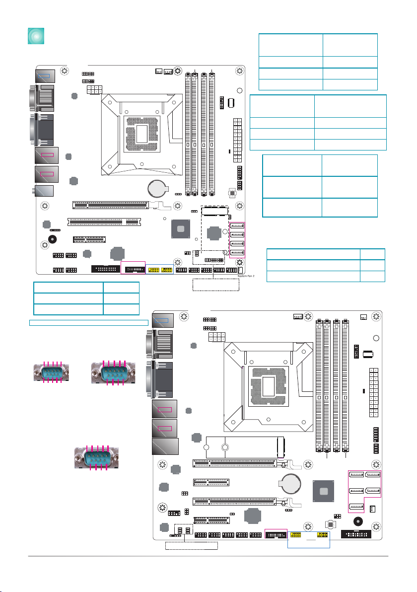
Board Layout and Jumper Settings
(WM343-KD330)
TPM (optional)
21
1314
LPC
SATA 1
1
SATA 3
SATA 0
SATA 2
SATA 3.0
1Chassis
Intrusion
1
1
1
PCIe 1 (PCIe x16 )
PCI 1
(DDR4_2, DDR4_4 for KD330-Q170 only)
System Fan 1
1
CPU Fan
1
1
5
COM 1
RS232/422/485
Select (JP10)
PTN3355
COM 1 RS232/422/485 Select (JP8)
+12V
Power
COM 1 RS232/Power Select (JP9)
51
6
2
51
6
2
51
6
2
51
6
2
4
8
COM 1
RS232/422/485
Select (JP7)
Standby
Power LED
1
ATX
Power
12 24
13
12
11
Front Panel
1 2
LAN LED
7 8
SPI Flash
BIOS
1
2
9
1
2
91
2
9
1
2
9
1
2
9
1
Clear CMOS
Data (JP1)
DDR4_1
DDR4_2
DDR4_3
DDR4_4
Socket LGA1151
Intel I219V (for KD330-H110)
Intel I219LM (for KD330-Q170)
Intel
I211AT
1
2
SMBus
5
1
2
5
6
Nuvoton
NCT6106D
1
2 6
5 1
26
5 1
2 6
5
(JP12)(JP11)(JP13)
(JP14)
Mini PCIe Signal Select (JP6)
(for KD330-Q170 only)
1
Battery
Intel
H110/Q170
COM 2 RS232/Power Select (JP14)
COM 2 RS232/422/485 Select (JP12)
COM 2 RS232/422/485 Select (JP13)
COM 2 RS232/422/485 Select (JP11)
COM 6
COM 5
COM 4
COM 3
COM 2
USB 3.0
DIO
1
2
10
USB 7-8
USB 2.0
1
2
19
11
10 1
USB 5-6
1
2
10
USB 9-10
(for KD330-Q170 only)
iTE
IT8893E
1
2
91
2
9
1
2
9
COM 7
(optional)
1
2
9
COM 8
(optional)
COM 9
(optional)
COM 10
(optional)
1
Buzzer
S/PDIF
Realtek
ALC888S
Nuvoton
NCT5104D
(optional)
PCIe 2 (PCIe x4)
LAN 1
COM 1
VGA
PS/2 KB/MS
USB 5-6
USB 2.0
LAN 1
USB 1-2
USB 3.0
LAN 2
USB 3-4
USB 3.0
I C
Line-out
Mic-in
1
Mini PCIe
(for KD330-Q170 only)
DVI-I (DVI-D signal)
DP++
5
3
7
7
7
7
2
3
3
3
4
WM343-KD331
M.2 M Key
(for KD331-Q170)
M.2 M Key Supports
Optane Memory
(for KD331-C236)
COM 2 RS232/422/485 Select (JP13)
COM 2 RS232/Power Select (JP14)
COM 2 RS232/422/485 Select (JP11)
COM 2 RS232/422/485 Select (JP12)
PCIe 4 (PCIe x4)
Standby
Power LED
ATX Power
1
12 24
13
USB 3.0
21
1314
LPC
TPM (optional)
Chassis Intrusion
1
1
S/PDIF
System Fan 2
1
1 2
11
Front Panel
1 2
LAN LED
7 8
1
1
1
1
SATA 1
SATA 3
SATA 0
SATA 2
SATA 4
SATA 3.0
1
5
2
SMBus
Buzzer
SPI Flash
BIOS
System
Fan 1
1
1
2
19 DIO
1
2
91
2
91
2
1
2
91
2
9
COM 5
COM 2 COM 6
COM 3 COM 4
1
2
10
USB 2.0
11
10 1
USB 5-6
Realtek ALC888S
Intel I211AT
PCIe 3 (PCIe x16)
1
2
10
1
1
2
5
6
(JP12)
1
2
5
6
(JP13)
1
2
9
10
Front
Audio
1
2
5
6
Intel I211AT
Intel I211AT
1
2 6
5
1
Clear CMOS
Data (JP1)
C236/Q170
Intel
Nuvoton
NCT6106D
PCIe 2 (PCIe x4)
Battery
DDR4_1 DDR4_3
DDR4_4
DDR4_2
PCIe 1 (PCIe x16)
CPU Fan
1
COM 1 RS232/422/485 Select (JP8)
COM 1
RS232/422/485
Select (JP10)
51
62
51
62
51
62
51
62
COM 1 RS232/Power Select (JP9)
1
5
4
8
+12V
Power
COM 1
RS232/422/485
Select (JP7)
PTN3355
Intel I219LM
PS/2 KB/MS
USB 5-6
USB 2.0
LAN 1
USB 1-2
USB 3.0
LAN 2
USB 3-4
USB 3.0
Socket LGA1151
COM1
VGA
DVI-I (DVI-D signal)
DP++
LAN 3-4
5
43
2
7
77
7
7
3
USB 9-10
or Optional
Vertical USB
USB 7-8
3
RS232/422/485 JP7 (COM 1)
JP11 (COM 2)
RS232 (default) 1-2 On
RS422 Full Duplex 3-4 On
RS485 5-6 On
Clear CMOS Data JP1
Normal (default) 1-2 On
Clear CMOS Data 2-3 On
RS232/Power JP9 (COM 1)
JP14 (COM 2)
RS232 (default) 1-3 (RI),
2-4 (DCD) On
RS232 with
power
3-5 (+5V),
4-6 (+12V) On
Mini PCIe/mSATA Signal JP6
Mini PCIe (default) 1-2 On
mSATA 2-3 On
The following jumper settings are for
WM343-KD330 (Intel® Q170) only.
RS232/422/485 JP8/JP10 (COM 1)
JP12/JP13 (COM 2)
RS232 (default) 1-3, 2-4 On
RS422 Full Duplex 3-5, 4-6 On
RS485 3-5, 4-6 On
Notes:
1. When COM 1 RS232/422/485 is
selected, JP8 and JP10 must be set in
accordance to JP7.
2. When COM 2 RS232/422/485 is
selected, JP12 and JP13 must be set
in accordance to JP11.
COM 1/COM 2: RS232 with power/422/485
6789
12 3 4 5
DCD
(or +12V)
RXD
TXD
DTR
GND
DSR
RTS
CTS
RI
(or +5V)
RS232
DATA+
DATA-
N.C.
N.C.
GND
245
3
1
7
6 8 9
N.C.
N.C.
N.C.
N.C.
RS422
N.C.
N.C.
N.C.
N.C.
245
3
1
7
6 8 9
RXD+
RXD-
TXD+
TXD-
GND
RS485
933-WM3434-000G
A49901945

Other manuals for WM343-KD330

1

This manual suits for next models

2

Other DFI Computer Hardware manuals

DFI HM960-QM87 User manual

DFI

DFI HM960-QM87 User manual

DFI EC90A-AL User manual

DFI

DFI EC90A-AL User manual

DFI HR908-B User manual

DFI

DFI HR908-B User manual

DFI CL60-LX User manual

DFI

DFI CL60-LX User manual

DFI EC70A-TGU User manual

DFI

DFI EC70A-TGU User manual

DFI HU968 User manual

DFI

DFI HU968 User manual

DFI BT9A3 Series User manual

DFI

DFI BT9A3 Series User manual

DFI CR901-B User manual

DFI

DFI CR901-B User manual

DFI HM920-QM87 User manual

DFI

DFI HM920-QM87 User manual

DFI PA33 User manual

DFI

DFI PA33 User manual

DFI ADP253 User manual

DFI

DFI ADP253 User manual

DFI BT9A3 Series User manual

DFI

DFI BT9A3 Series User manual

DFI PR811-C622 User manual

DFI

DFI PR811-C622 User manual

DFI VC900-M8M User manual

DFI

DFI VC900-M8M User manual

DFI QRB551 User manual

DFI

DFI QRB551 User manual

DFI ES220-CS User manual

DFI

DFI ES220-CS User manual

DFI PW35 Series User manual

DFI

DFI PW35 Series User manual

DFI RPP051 User manual

DFI

DFI RPP051 User manual

DFI EHL051 User manual

DFI

DFI EHL051 User manual

DFI ADN171 User manual

DFI

DFI ADN171 User manual

DFI GH960 User manual

DFI

DFI GH960 User manual

DFI EC200 Series User manual

DFI

DFI EC200 Series User manual

DFI Multi-Function Series User manual

DFI

DFI Multi-Function Series User manual

DFI CMS101 User manual

DFI

DFI CMS101 User manual

Popular Computer Hardware manuals by other brands

Tektronix TMSST1 instruction manual

Tektronix

Tektronix TMSST1 instruction manual

Renesas MCU Board for PC4400 Emulator System... user manual

Renesas

Renesas MCU Board for PC4400 Emulator System... user manual

Noctua NF-A14 5V user manual

Noctua

Noctua NF-A14 5V user manual

EverFocus EP8BQ user manual

EverFocus

EverFocus EP8BQ user manual

Analog Devices EVAL-ADAQ8088EBZ user guide

Analog Devices

Analog Devices EVAL-ADAQ8088EBZ user guide

Hitachi H8S/2378, H8S/2378R Series Hardware manual

Hitachi

Hitachi H8S/2378, H8S/2378R Series Hardware manual

Texas Instruments ADS61B23EVM user guide

Texas Instruments

Texas Instruments ADS61B23EVM user guide

Kontron COMe Eval Carrier T7 user guide

Kontron

Kontron COMe Eval Carrier T7 user guide

Renesas EK-RA6M3 Getting started

Renesas

Renesas EK-RA6M3 Getting started

Epson S5U13719P00C100 user manual

Epson

Epson S5U13719P00C100 user manual

IEI Technology PCIE-G41A2 Quick installation guide

IEI Technology

IEI Technology PCIE-G41A2 Quick installation guide

Siemens SMP16-CPU06 Series manual

Siemens

Siemens SMP16-CPU06 Series manual

Leicke HEBRON LW20 Series user manual

Leicke

Leicke HEBRON LW20 Series user manual

Intashield IS-200 Specifications

Intashield

Intashield IS-200 Specifications

SIMCom Wireless Solutions SIM8262E-M2 instructions

SIMCom Wireless Solutions

SIMCom Wireless Solutions SIM8262E-M2 instructions

EK-Quantum Momentum2 ROG Strix X570-i Gaming D-RGB quick start guide

EK-Quantum

EK-Quantum Momentum2 ROG Strix X570-i Gaming D-RGB quick start guide

ekwb EK-Vector RTX 2080 FTW3 installation manual

ekwb

ekwb EK-Vector RTX 2080 FTW3 installation manual

Renesas IE-703107-MC-EM1 user manual

Renesas

Renesas IE-703107-MC-EM1 user manual

manuals.online logo
manuals.online logoBrands
  • About & Mission
  • Contact us
  • Privacy Policy
  • Terms and Conditions

Copyright 2025 Manuals.Online. All Rights Reserved.