manuals.online logo
Brands
  1. Home
  2. •
  3. Brands
  4. •
  5. DFI
  6. •
  7. Motherboard
  8. •
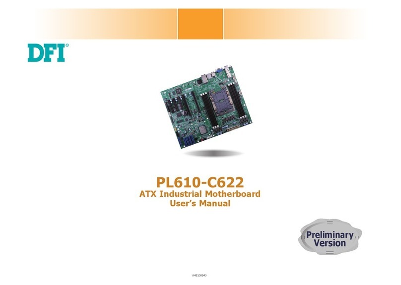
  9. DFI CW65 Series User manual

DFI CW65 Series User manual

CW65 Series
Rev. CA+
403F0016
System Board Users Manual
Carte Mère Manuel Pour Utilisateur
System-Platine Benutzerhandbuch
Tablero Electrónico del Sistema Manual del
Usuario
Copyright
This publication contains information that is protected by copyright. No part of it may
be reproduced in any form or by any means or used to make any transformation/
adaptation without the prior written permission from the copyright holders.
This publication is provided for informational purposes only. The manufacturer makes
no representations or warranties with respect to the contents or use of this manual and
specifically disclaims any express or implied warranties of merchantability or fitness
for any particular purpose.The user will assume the entire risk of the use or the results
of the use of this document. Further, the manufacturer reserves the right to revise this
publication and make changes to its contents at any time, without obligation to notify
any person or entity of such revisions or changes.
© 1999. All Rights Reserved.
Trademarks
Microsoft®MS-DOS®, WindowsTM, Windows®95 and Windows®98 are registered
trademarks of Microsoft Corporation. Intel®, Pentium®III and CeleronTM are registered
trademarks of Intel Corporation. Award is a registered trademark of Award Software,
Inc. Other trademarks and registered trademarks of products appearing in this manual
are the properties of their respective holders.
Caution:
Danger of explosion if battery incorrectly replaced.
Replace only with the same or equivalent type recommended by the
manufacturer.
Dispose of used batteries according to the battery manufacturers instructions.
FCC and DOC Statement on Class B
This equipment has been tested and found to comply with the limits for a Class
B digital device, pursuant to Part 15 of the FCC rules. These limits are designed
to provide reasonable protection against harmful interference when the
equipment is operated in a residential installation. This equipment generates, uses
and can radiate radio frequency energy and, if not installed and used in
accordance with the instruction manual, may cause harmful interference to radio
communications. However, there is no guarantee that interference will not occur
in a particular installation. If this equipment does cause harmful interference to
radio or television reception, which can be determined by turning the equipment
off and on, the user is encouraged to try to correct the interference by one or
more of the following measures:
 Reorient or relocate the receiving antenna.
 Increase the separation between the equipment and the receiver.
 Connect the equipment into an outlet on a circuit different from that to
which the receiver is connected.
 Consult the dealer or an experienced radio TV technician for help.
Notice:
1. The changes or modifications not expressly approved by the party
responsible for compliance could void the user's authority to operate the
equipment.
2. Shielded interface cables must be used in order to comply with the emission
limits.
Table of Contents / Table des Matières / Inhaltsverzeichnis / Tabla de Contenidos
Chapter 1 - Introduction
1.1 Features and Specifications............................................................................................
1.2 Package Checklist................................................................................................................
Chapter 2 - Hardware Installation
2.1 System Board Layout ......................................................................................................
2.2 Jumper Settings for Clearing CMOS Data............................................................
2.3 Jumper Settings for Wake-On-Keyboard/Mouse...................................................
2.4 Jumper Settings for the Systems Beep Message...............................................
2.5 Jumper Settings for the Boot Block Lock/Unlock.............................................
2.6 Jumper Settings for the CPUs Front Side Bus...................................................
2.7 Jumper Settings for the Audio Codec......................................................................
2.8 Connectors..............................................................................................................................
Chapter 3 - Award BIOS Setup Utility
3.1 Entering the Award BIOS Setup Utility....................................................................
3.2 Setting the Date and Time..............................................................................................
3.3 Selecting the Hard Drive and Floppy Drive Type............................................
3.4 Selecting the Boot Sequence of the Drives..........................................................
3.5 Enabling the AC97 Modem............................................................................................
3.6 Setting the Wake-On-Keyboard/Mouse Function..............................................
3.7 Selecting the Power Lost Resume State..................................................................
3.8 Selecting the CPU Ratio..................................................................................................
3.9 Using the Suspend to RAM Function.......................................................................
3.10 Loading Fail-Safe Defaults/Optimized Defaults...................................................
3.11 Setting the Supervisor/User Password...................................................................
Chapter 4 - Supported Softwares
4.1 Hardware Doctor Utility................................................................................................
4.2 Intel 810 INF Update Utility for Windows®95/98.......................................
4.3 Intel 810 Graphics Drivers for Windows.............................................................
4.4 SoundMAX Audio Drivers for Windows..............................................................
4.5 Drivers and Utilities Installation Notes....................................................................
4
22
46
47
48
50
51
52
56
58
61
64
65
24
25
27
29
30
31
33
37
67
68
70
71
72
Note:
The users manual in the provided CD contains detailed information about the
system board. If, in some cases, some information doesnt match those shown in this
manual, this manual should always be regarded as the most updated version. To
view the users manual, insert the CD into a CD-ROM drive. The autorun screen
(Main Board Utility CD) will appear. Click Users Manual.
Introduction
1
4
Expansion Slots
The system board is equipped with 5 dedicated PCI slots and 1 AMR slot. AMR
(Audio/Modem Riser) is an interface designed for installing an audio riser card,
modem riser card or audio/modem riser card that is compliant to the AMR
specification.
Onboard Graphics Features
 Graphics memory
- Shares 1MB of the system memory. This is fixed regardless of the size of
the system memory.
- Uses the Dynamic Video Memory Technology (DVMT) technology. This
freely changes in size because graphics memory is allocated from the sys-
tem memory according to current needs.
1.1 Features and Specifications
Caractéristiques et Spécifications
Leistungsmerkmale und Technische Daten
Características y Especificaciones
1.1.1 Features
Chipset
 Intel®810-E (CW65-E)
Intel®810 DC-100 (CW65-D)
Intel®810 (CW65-S)
Intel®810-L (CW65-L)
Processor
The system board is equipped with a switching voltage regulator that
automatically detects 1.30V to 2.05V.
 Pentium®III FCPGA 133MHz FSB (533EB-866EB) processor (CW65-E)
 Pentium®III FCPGA 100MHz FSB (500E-700E) processor
 CeleronTM 66MHz FSB: FCPGA (566MHz-600MHz) or PPGA (300A-
533MHz) processor
System Memory
 16MB to 256MB/512MB memory using unbuffered DIMMs with 64Mbit/
128Mbit technology. (You must use 32MBx64 SDRAM DIMM to support
512MB memory.)
 Two 168-pin DIMM sockets
 Uses x64 PC-100 SDRAM DIMM, 3.3V
Chapter 1 - Introduction
Introduction
Einleitung
Introducción
DIMMs
2MBx64
4MBx64
8MBx64
Memory Size
16MB
32MB
64MB
English
DIMMs
16MBx64
32MBx64
Memory Size
128MB
256MB
1
Introduction
5
- 4MB onboard display cache (CW65-E and CW65-D only)
 Graphics controller
- 100MHz (CW65-D) or 133MHz (CW65-E) super AGP performance us-
ing 4MB display cache memory
- 3D hyper pipelined architecture
- 2D hardware and motion video acceleration
- 9-bit precision hardware motion compensation assistance for software
MPEG2 decode
- Software DVD at 30fps
 2D graphics features
- Resolution: up to 1600x1200 in 8-bit color at 85Hz refresh
- 64-bit blitter with enhancements
- 64x64x3 color transparent cursor
- Arithmetic stretch blitter
 3D graphics features
- 600K-700K tri/sec sustained
- 55Mpixels/sec
- Flat and Gouraud shading
- MIP mapping with bi-linear and anisotropic filtering
- 16-bit color/Z-buffering
- Discrete/strips/fans
- Anisotropic filtering
- Texture compositing, color keying and chroma keying
 Software drivers
- Windows®95/98
- Windows NT®4.0
Onboard Audio Features
 Supports Microsoft®DirectSound
 32-voice wavetable synthesis
 AC97 supported with full duplex, independent sample rate converter for au-
dio recording and playback
 Downloadable sound (DLS) level-1
Compatibility
 Microsoft®PC 98 compliant
 VESA Display Power Management Signaling (DPMS)
 VESA DDC2B for Plug and Play monitors
 PCI 2.2, AMR 1.0 and AC97 compliant
ATX Double Deck Ports (PC 99 color-coded connectors)
 Two USB ports
 One NS16C550A-compatible DB-9 serial port
 One DB-15 VGA port
 One SPP/ECP/EPP DB-25 parallel por t
 One mini-DIN-6 PS/2 mouse port
 One mini-DIN-6 PS/2 keyboard port
 One game/MIDI port
 Three audio jacks: line-out, line-in and mic-in
Connectors
 One 9-pin connector for external serial port
 One connector for IrDA interface
 Two IDE connectors
 One floppy drive connector supports up to two 2.88MB floppy drives
 One 20-pin ATX power supply connector
 One 3-pin Wake-On-LAN connector
Introduction
1
6
 CPU, chassis and second chassis fan connectors
 One opened chassis alarm connector
 Three CD audio-in connectors (2 Sony and 1 Mitsumi)
PCI Bus Master IDE Controller
 Two PCI IDE interfaces support up to four IDE devices
 Supports Ultra ATA/33 (CW65-L) or ATA/66 (CW65-E, CW65-D or
CW65-S) hard drives
 PIO Mode 4 Enhanced IDE (data transfer rate up to 14MB/sec.)
 Bus mastering reduces CPU utilization during disk transfer
 Supports ATAPI CD-ROM, LS-120 and ZIP
IrDA Interface
The system board is equipped with an IrDA connector for wireless connectivity
between your computer and peripheral devices. It supports peripheral devices
that meet the IrDA or ASKIR standard.
USB Ports
The system board is equipped with two USB ports. USB allows data exchange
between your computer and a wide range of simultaneously accessible external
Plug and Play peripherals.
BIOS
 Award BIOS, Windows®95/98 Plug and Play compatible
 Supports SCSI sequential boot-up
 Flash EPROM for easy BIOS upgrades (4Mbit)
 Includes NCR 810 SCSI BIOS
 Supports DMI 2.0 function
Desktop Management Interface (DMI)
The system board comes with a DMI 2.0 built into the BIOS. The DMI utility in
the BIOS automatically records various information about your system
configuration and stores these information in the DMI pool, which is a part of
the system board's Plug and Play BIOS. DMI, along with the appropriately
networked software, is designed to make inventory, maintenance and
troubleshooting of computer systems easier.
1.1.2 System Health Monitor Functions
The system board is capable of monitoring the following system health
conditions.
 Monitors processor/system temperature and overheat alarm
 One optional temperature sensor for user customization
 Monitors 5VSB/VBAT/1.5V/3.3V/5V/±12V/processor voltages and failure
alarm
 Monitors the fan speed of the processor fan, chassis fan and second chassis
fan; controls the fan speed of the processor and chassis fans; and failure
alarm
 Automatic fan on/off control
 Read back capability that displays temperature, voltage and fan speed
 Opened chassis alarm
 Suppor ts Intel®processor thermal diode output (real processor
temperature)
If you want a warning message to pop-up or a warning alarm to sound when an
abnormal condition occurs, you must install the Hardware Doctor utility. This
utility is included in the CD that came with the system board. Refer to the
Hardware Doctor Utility section in chapter 4 for more information.
1
Introduction
7
1.1.3 Intelligence
Automatic CPU/Chassis Fan Off
The CPU and chassis fans will automatically turn off once the system enters the
Suspend mode.
Dual Function Power Button
Depending on the setting in the Soft-Off By PWR-BTTN field of the Power
Management Setup, this switch will allow the system to enter the Soft-Off or
Suspend mode.
External Modem Ring-on
The Modem Ring-on feature allows the system that is in the Suspend mode or
Soft Power Off mode to wake-up/power-on to respond to incoming calls. This
feature supports external modem only.
RTC Timer to Power-on the System
The RTC installed on the system board allows your system to automatically
power-on on the set date and time.
Wake-On-LAN Ready
The Wake-On-LAN function allows the network to remotely wake up a Soft
Power Down (Soft-Off) PC. Your LAN card must support the remote wakeup
function.
Important:
If you are using the (1) Suspend to RAM, (2) Wake-On-Keyboard/Mouse and
(3) Wake-On-LAN functions all at the same time, the 5VSB power source of
your power supply must support a minimum of
≥
1A. A
≥
720mA 5VSB
power source is sufficient if you are using only one or two of these functions.
Wake-On-Keyboard/Wake-On-Mouse
This function allows you to use the keyboard or PS/2 mouse to power-on the
system. Refer to Jumper Settings for Wake-On-Keyboard/Mouse in chapter 2
and Setting the Wake-On-Keyboard/Mouse Function in chapter 3 for more
information.
Important:
 The power button will not function once a keyboard password has been
set in the KB Power On Password field of the Integrated Peripherals
submenu. You must type the correct password to power-on the system. If
you forgot the password, power-off the system and remove the battery.
Wait for a few seconds and install it back before powering-on the
system.
 If you are using the (1) Suspend to RAM, (2) Wake-On-Keyboard/Mouse
and (3) Wake-On-LAN functions all at the same time, the 5VSB power
source of your power supply must support a minimum of
≥
1A. A
≥
720mA 5VSB power source is sufficient if you are using only one or
two of these functions.
AC Power Failure Recovery
When power returns after an AC power failure, you may choose to either
power-on the system manually, let the system power-on automatically or return
to the state where you left off before power failure occurs. Refer to Selecting
the Power Lost Resume State in chapter 3 for more information.
Year 2000 Compliant
 Supports hardware Y2K function.
 Supports hardware Random Number Generator (RNG) to enable a new se-
curity and manageability infrastructure for PC.
Introduction
1
8
ACPI
The system board is designed to meet the ACPI (Advanced Configuration and
Power Interface) specification. ACPI has energy saving features that enables PCs
to implement Power Management and Plug-and-Play with operating systems that
support OS Direct Power Management. Currently, only Windows®98 supports
the ACPI function. ACPI when enabled in the Power Management Setup will allow
you to use the Suspend to RAM function.
With the Suspend to RAM function enabled, you can power-off the system at
once by pressing the power button or selecting Standby when you shut down
Windows®98 without having to go through the sometimes tiresome process of
closing files, applications and operating system. This is because the system is
capable of storing all programs and data files during the entire operating session
into RAM (Random Access Memory) when it powers-off. The operating session
will resume exactly where you left off the next time you power-on the system.
Refer to Using the Suspend to RAM Function in chapter 3 for more
information.
Important:
If you are using the (1) Suspend to RAM, (2) Wake-On-Keyboard/Mouse and
(3) Wake-On-LAN functions all at the same time, the 5VSB power source of
your power supply must support a minimum of
≥
1A. A
≥
720mA 5VSB
power source is sufficient if you are using only one or two of these functions.
Virus Protection
Most viruses today destroy data stored in hard drives. The system board is
designed to protect the boot sector and partition table of your hard disk drive.
1.1.1 Caractéristiques
Chipset
 Intel®810-E (CW65-E)
Intel®810 DC-100 (CW65-D)
Intel®810 (CW65-S)
Intel®810-L (CW65-L)
Processeur
La carte système est équipée dun régulateur de commutation de voltage qui
détecte automatiquement de 1.30V à 2.05V.
 Pentium®III FCPGA 133MHz FSB (533EB-866EB) processeur (CW65-E)
 Pentium®III FCPGA 100MHz FSB (500E-700E) processeur
 CeleronTM 66MHz FSB: FCPGA (566MHz-600MHz) ou PPGA (300A-
533MHz) processeur
Mémoire Système
 Mémoire allant de 16Mo à 256Mo/512Mo utilisant la technologie DIMM
sans mémoire tampon de 64Mo/128Mo. (Vous devez utiliser des DIMM
SDRAM 32Mox64 pour supporter la mémoire de 512Mo.)
 Deux sockets DIMM 168 broches.
 Utilise x64 DIMM SDRAM PC-100, 3.3V
Français
DIMMs
2MBx64
4MBx64
8MBx64
Mémoire
16MB
32MB
64MB
DIMMs
16MBx64
32MBx64
Mémoire
128MB
256MB
1
Introduction
9
Logements dExtension
La carte système est équipée de 5 logements PCI dédiés et 1 logement AMR.
AMR (Riser Audio/Modem) est dune interface destinée à linstallation dune carte
audio riser, carte modem riser ou dune carte audio/modem réhausseur
conforme aux spécifications AMR.
Caractéristiques Graphiques sur Carte
 Mémoire graphique
- Partage 1Mo de la mémoire système. Ceci est fixé indépendament de la
taille de la mémoire système.
- Utilise la technologie de Dynamic Video Memory Technology (DVMT).
Cela change librement de taille parce que la mémoire graphique est
allouée depuis la mémoire système en fonction des besoins du moment.
- Mémoire cache daffichage sur carte de 4Mo (CW65-E et CW65-D
seulement).
 Contrôleur Graphique
- Performances super AGP 100MHz (CW65-D) ou 133MHz (CW65-E)
utilisant 4Mo de mémoire cache daffichage.
- Architecture en hyper pipeline 3D
- Accélération vidéo de matériel et de mouvement 2D
- Assistance de compensation de mouvement de matériel de précision 9
bits pour logiciel MPEG2 décode
- Logiciel DVD à 30fps
 Caractéristiques graphiques 2D
- Résolution: jusquà 1600x1200 en 8 bits couleur à rafraîchissement en
85Hz
- Blitter 64 bits avec améliorations
- Curseur transparent couleur 64x64x3
- Blitter détirement arithmétique
 Caractéristiques graphiques 3D
- Maintien 600K-700K tri/sec
- 55Mpixels/sec
- Ombrage à Plat et Gouraud
- MIP mappage avec filtrage bilinéaire et anisotropique
- Mémoire tampon 16 bits couleur/Z
- Discret/bandes/ventilateurs
- Filtrage anistropique
- Composition de texture, saisie de couleur et saisie de chroma
 Logiciels Pilotes
- Windows®95/98
- Windows NT®4.0
Caractéristiques Audio sur Carte
 Supporte DirectSound de Microsoft®
 Synthèse wavetable 32 Voies
 AC97 supporté avec full duplex, convertisseur de vitesse déchantillonnage
indépendant pour enregistrement audio et lecture.
 Son (DLS) Niveau-1 téléchargeable.
Compatibilité
 Compatible Microsoft®PC 98
 Signalisation de Gestion dAlimentation dAffichage (DPMS) VESA
 VESA DDC2B pour moniteurs Plug & Play
 Compatible PCI 2.2, AMR 1.0 et AC97
Ports Double Module ATX (Connecteurs PC 99 avec codes couleur)
 Deux Por ts USB
 Un port série DB-9 compatible NS16C550A
Introduction
1
10
 Un port VGA DB-15
 Un port parallèle DB-25 SPP/ECP/EPP
 Un port souris PS/2 mini-DIN-6
 Un port clavier PS/2 mini-DIN-6
 Un por t jeu/MIDI
 Trois prises audio: ligne de sortie (line-out), ligne dentrée (line-in) et entrée
micro (mic-in)
Connecteurs
 Un connecteur 9 broches pour por t série externe
 Un connecteur pour interface IrDA
 Deux connecteurs IDE
 Un connecteur de lecteur de disquettes supportant jusquà deux lecteurs de
disquettes de 2.88Mo
 Un connecteur dalimentation ATX 20 broches
 Un connecteur Wake-On-LAN 3 broches
 Connecteurs de ventilateurs de CPU, de châssis et de second ventilateur de
châssis
 Connecteur dalarme de châssis ouvert
 Trois connecteurs dentrée audio CD (2 Sony et 1 Mitsumi)
Contrôleur IDE de BUS Maître PCI
 Deux interfaces PCI IDE supportant jusquà quatre matériels IDE
 Supporte des disques durs Ultra ATA/33 (CW65-L) ou ATA/66 (CW65-E,
CW65-D ou CW65-S)
 IDE Améliorés Mode 4 PIO (vitesse de transfer t de données allant jusquà
14Mo/sec.)
 La gestion de Bus réduit lutilisation du CPU pendant les transferts sur
disque
 Supporte les CD-ROM ATAPI, LS-120 et ZIP
Interface IrDA
La carte système est équipée dun connecteur IrDA pour les connexions sans fil
entre votre ordinateur et des périphériques. Il supporte les périphériques qui
sont conformes aux standards IrDA ou ASKIR.
Ports USB
La carte système est équipée de deux ports USB. USB permet léchange de
données entre votre ordinateur et un grande éventail de périphériques externes
Plug and Play accessibles simultanément.
BIOS
 Compatible avec Award BIOS, Windows®95/98 Plug and Play
 Supporte lamorçage séquentiel SCSI
 EPROM Flash pour une mise à niveau facile du BIOS (4Mbits)
 Comprend le BIOS NCR 810 SCSI
 Supporte la fonction DMI 2.0
Interface de Gestion de Bureau (DMI)
La carte système est livrée avec un DMI 2.0 intégré au BIOS. Lutilitaire DMI
dans le BIOS enregistre automatiquement diverses informations concernant la
configuration de votre système et stocke ces informations dans la liste DMI, qui
est une partie du BIOS Plug and Play de la carte système. DMI, accompagné
du logiciel en réseau approprié, est conçu pour rendre linventaire, lentretien et
le dépannage du système de lordinateur plus facile.
1
Introduction
11
1.1.2 System Health Monitor Fonctions
La carte système est capable de gérer les conditions de santé système
suivantes.
 Gère lalarme de température et de surchauffe de processeur / de système
 Un capteur de température optionnel pour personnalisation utilisateur
 Gère lalarme de voltage et déchec de 5VSB/VBAT/1.5V/3.3V/5V/±12V/
processeur
 Gère la vitesse de ventilateur du ventilateur de processeur, de ventilateur de
châssis et de second ventilateur de châssis; contrôle la vitesse de ventilateur
des ventilateurs de processeur et de châssis; et alarme de défaillance.
 Contrôle automatique de marche/arrêt de ventilateur
 Capacité de relecture qui affiche la température, le voltage et la vitesse de
ventilateur
 Alarme de châssis ouvert
 Support la diode thermale de sortie de processeur Intel®(température réelle
de processeur).
Si vous désirez quun message davertissement apparaisse ou quune alarme
retentisse lorsque quune condition anormale se produit, vous devez installer
lutilitaire Hardware Doctor. Cet utilitaire est compris dans le CD qui est livré
avec la carte système. Repor tez vous à la section concernant lUtilitaire
Hardware Doctor dans le chapitre 4 pour de plus amples informations.
1.1.3 Intelligence
Arrêt automatique de Ventilateur de CPU/Châssis
Les ventilateurs de CPU et de châssis sarrêteront automatiquement une fois que
le système est entré en mode Suspension.
Bouton dAlimentation à Fonction Double
En fonction du paramétrage dans le champ Soft-Off By PWR-BTTN du
Programme dInstallation de la Power Management Setup, ce commutateur
permettra à votre système dentrer en mode Soft-Off ou Suspension.
Modem Ring-on Externe
La fonction Modem Ring-on permet au système qui se trouve en mode
Suspension ou en mode Sof Power Off de se réveiller / sallumer afin de
répondre à un appel. Cette fonction supporte le modem externe seulement.
Minuterie RTC pour Allumer le Système
Le RTC installé sur la carte système permet à votre système de sallumer
automatiquement à une date et heure présélectionnée.
Wake-On-LAN Prêt
La fonction Wake-On-LAN permet au réseau de réveiller à distance un PC Mis
Hors Tension par Logiciel (Soft Power Down ou Soft- Off). Votre carte LAN
doit supporter la fonction de réveil à distance.
Important:
Si vous utilisez les fonctions (1) Suspension sur RAM, (2) Réveil-Sur-Clavier/
Souris (Wake-On-Keyboard/Mouse), et (3) Réveil-Sur-LAN (Wake-On-LAN)
toutes en même temps, assurez vous que la source dalimentation 5VSB
supporte un minimum de
≥
1A. Si vous utilisez seulement une ou deux de
ces fonctions,
≥
720mA sont suffisants.
Réveil-Sur-Clavier/Réveil-Sur-Souris
Cette fonction vous permet dutiliser le clavier ou la PS/2 souris pour allumer le
système. Reportez vous à Positionnement des Cavaliers pour Réveil-Sur-Clavier/
Introduction
1
12
Souris dans le chapitre 2 et à Activer la Fonction Réveil-Sur-Clavier/Souris dans
le chapitre 3 pour plus dinformations.
Important:
Le bouton dalimentation ne fonctionnera plus une fois que le mot de
passe de clavier aura été paramétré dans le champ KB Power On
Password du sous menu de Integrated Peripherals. Vous devez taper le
mot de passe correct pour allumer le système. Si vous avez oublié le
mot de passe, éteignez le système et retirez la batterie. Attendez
quelques secondes et réinstallez-la avant de rallumer le système.
Si vous utilisez les fonctions (1) Suspension sur RAM, (2) Réveil-Sur-
Clavier/Souris (Wake-On-Keyboard/Mouse), et (3) Réveil-Sur-LAN (Wake-
On-LAN) toutes en même temps, assurez vous que la source
dalimentation 5VSB supporte un minimum de
≥
1A. Si vous utilisez
seulement une ou deux de ces fonctions,
≥
720mA sont suffisants.
Récupération après Défaillance dAlimentation CA
Quand lalimentation revient après une défaillance dalimentation CA, vous pouvez
choisir dallumer le système manuellement, de laisser le système sallumer
automatiquement ou de retourner à létat que vous aviez quitté avant que la
défaillance dalimentation se produise. Reportez vous à Choisir létat de
Redémarrage Après Coupure de Courant dans le Chapitre 3 pour plus
dinformations.
Conformité An 2000
 Supporte la fonction matériel Y2K.
 Supporte le Générateur de Nombre Aléatoire (RNG) de matériel pour
permettre une nouvelle infrastructure de sécurité et de gestion pour PC.
ACPI
La carte système est conçue de façon à être conforme aux spécifications ACPI
(Configuration Avancée et Interface dAlimentation). ACPI comporte une fonction
déconomie dénergie qui permet aux PC de mettre en uvre la Gestion
dAlimentation et Plug and Play avec des systèmes dexploitation qui supportent
la Gestion dAlimentation Directe de Système dExploitation. Actuellement,
seulement Windows®98 supporte la fonction ACPI. Quand ACPI est activé dans
le Programme de Power Management Setup, cela vous permet dutiliser la
fonction de Suspension sur RAM.
Quand la fonction de Suspension sur RAM est activée, vous pouvez éteindre le
système immédiatement en appuyant sur le bouton dalimentation ou en
sélectionnant Veille quand vous éteignez Windows®98 sans avoir à passer par
le processus quelquefois ennuyeux de fermeture des fichiers, des applications et
du système dexploitation. Ceci est du au fait que le système est capable de
stocker tous les fichiers programmes et de données pendant toute la session
dutilisation dans la RAM (Mémoire à Accès Aléatoire) lorsque quil séteint. La
session dutilisation reprendra exactement où vous lavez laissée la prochaine fois
que vous allumerez le système. Reportez vous à Utilisation de la Fonction de
Suspension sur RAM dans le Chapitre 3 pour plus dinformations.
Important:
Si vous utilisez les fonctions (1) Suspension sur RAM, (2) Réveil-Sur-Clavier/
Souris (Wake-On-Keyboard/Mouse), et (3) Réveil-Sur-LAN (Wake-On-LAN)
toutes en même temps, assurez vous que la source dalimentation 5VSB
supporte un minimum de
≥
1A. Si vous utilisez seulement une ou deux de
ces fonctions,
≥
720mA sont suffisants.
1
Introduction
13
Deutsch
Erweiterungssteckfasssungen
Die Systemplatine ist mit 5 dedizierten PCI-Steckfassungen und 1 AMR-
Steckfassung ausgestattet. AMR (Audio-/Modem-Riser) ist eine Schnittstelle für die
Installation einer Audio-Riserkarte, einer Modem-Riserkarte oder einer Audio-/
Modem-Riserkarte, die der AMR-Vorschrift entspricht.
Grafikmerkmale auf Platine
 Grafikspeicher
- Gemeinsame Anwendung von 1MB des Systemspeichers. Dies wurde
ungeachtet der Größe des Systemspeichers fest eingestellt.
- Anwendung der Technik des Dynamic Video Memory Technology
(DVMT). Die Größe dieses Speichers ist flexibel, da der Grafikspeicher
durch den Systemspeicher je nach aktueller Anforderung zugeordnet wird.
- 4MB-Anzeige-Cache auf Platine (nur für CW65-E und CW65-D).
 Grafik-Controller
- 100MHz (CW65-D) oder 133MHz (CW65-E) Super-AGP-Leistung mit
einem Anzeige-Cache-Speicher von 4MB.
- 3D-Hyper-Pipeline-Architektur.
- 2D-Hardware- und Bewegungsvideo-Beschleunigung.
- 9-Bit-Präzisions-Hardware-Bewegungsausgleichshilfe für die Dekodierung
der MPEG2-Software.
- Software-DVD mit 30 Bildern pro Sekunde.
DIMMs
2MBx64
4MBx64
8MBx64
Speicher
16MB
32MB
64MB
DIMMs
16MBx64
32MBx64
Speicher
128MB
256MB
Protection contre les Virus
La plupart des virus détruisent les données stockées sur les disques durs. La
carte système est conçue pour protéger le secteur damorçage et la table de
partition de votre disque dur.
1.1.1 Leistungsmerkmale
Chipset
 Intel®810-E (CW65-E)
Intel®810 DC-100 (CW65-D)
Intel®810 (CW65-S)
Intel®810-L (CW65-L)
Prozessor
Die Systemplatine ist mit einem Spannungsregler ausgestattet, durch welchen
automatisch Spannungen von 1,30V bis 2,05V festgestellt werden.
 Pentium®III FCPGA 133MHz FSB (533EB-866EB) prozessor (CW65-E)
 Pentium®III FCPGA 100MHz FSB (500E-700E) prozessor
 CeleronTM 66MHz FSB: FCPGA (566MHz-600MHz) oder PPGA (300A-
533MHz) prozessor
Systemspeicher
 Speicher von 16MB bis 256MB/512MB mit DIMMs ohne Puffer mit 64Mbit/
128Mbit (zum Unterstützen des 512MB-Speichers muß der 32MB´64
SDRAM-DIMM benutzt werden).
 Zwei DIMM-Fassungen mit 168poligem Anschlußstecker.
 Anwendung des ´64 PC-100 SDRAM-DIMMs, 3,3V.
Introduction
1
14
 2D-Grafikmerkmale
- Auflösungsvermögen: bis zu 1600´1200 in 8-Bit-Farben mit einer
Aktualisierungsrate von 85Hz.
- 64-Bit-Blitter mit Verstärkungen.
- Farbtransparenter Cursor, 64´64´3.
- Arithmetisches Stretch-Blitter.
 3D-Grafikmerkmale
- Unterstützt 600K-700K tri/Sek.
- 55Mpixels/Sek.
- Flache und Gouraud-Schattierung
- MIP-Abbilden mit bilinearer und anisotropischer Filterung
- 16-Bit-Farben/Z-Puffern
- Diskret/Streifen/Ventilator
- Anisotropische Filterung
- Texturkomposition und Farbnuancierung
 Softwaretreiber
- Windows®95/98
- Windows NT®4.0
Audiomerkmale auf Platine
 Unterstützung des Microsoft®DirectSound
 32-Stimmen-Wavetable-Synthese
 AC97 mit Unterstützung des Vollduplexbetriebs, unabhängigem
Abtastratenumwandler für die Aufnahme und Wiedergabe
 Herunterladbarer Klang (DLS) Niveau-1
Kompatibilität
 Kompatibilität mit Microsoft®PC 98
 VESA-Bildschirm mit Energieverwaltungs-Signalisierung (DPMS)
 VESA-DDC2B-Monitore für Plug and Play
 Kompatibilität mit PCI 2.2, AMR 1.0 und AC97
ATX-Zweietagen-Anschlüsse (PC 99 mit farbkodierten Steckverbindungen)
 Zwei USB-Anschlüsse
 Ein serieller DB-9-Anschluß, kompatibel mit NS16C550A
 Ein DB-15-VGA-Anschluß
 Ein DB-25-Parallelanschluß SPP/ECP/EPP
 Ein Mini-DIN-6-Anschluß für eine PS/2-Maus
 Ein Mini-DIN-6-Anschluß für eine PS/2-Tastatur
 Ein Spiel-/MIDI-Anschluß
 Drei Audio-Anschlußbuchsen: Ausgangsleitung, Eingangsleitung und Mikrofon-
Eingang
Anschlußstecker
 Ein 9poliger Anschlußstecker für den externen seriellen Anschluß
 Ein Anschluß für die IrDA-Schnittstelle
 Zwei IDE-Anschlüsse
 Unterstützung von bis zu zwei 2,88MB-Floppylaufwerken durch einen
Floppylaufwerksanschluß
 Ein 20poliger Anschlußstecker für das ATX-Netzgerät
 Ein 3poliger Anschlußstecker für Wecken durch LAN
 CPU-, Chassis- und zweiter Chassisventilator-Anschlüsse.
 Ein Anschluß für akustische Warnsignale bei geöffneter Chassis
 Drei CD-Eingangsanschlüsse (2 Sony und 1 Mitsumi)
PCI-Bus-Master-IDE-Controller
 Unterstützung von bis zu vier IDE-Geräten durch zwei PCI-IDE-Schnittstellen.
 Unterstützung der Festplatten Ultra ATA/33 (CW65-L) oder ATA/66 (CW65-E,
CW65-D oder CW65-S).
1
Introduction
15
 Erweitertes IDE des PIO-Modus 4 (Datenübertragungsgeschwindigkeit von
bis zu 14MB/Sek.).
 Verminderte CPU-Benutzung während Diskettenübertragung dank dem Bus-
Master.
 Unterstützung des ATAPI CD-ROMs, LS-120 und ZIP.
IrDA-Schnittstelle
Die Systemplatine ist mit einem IrDA-Anschluß versehen, durch welche eine
kabellose Verbindung zwischen Ihrem Computer und Peripheriegeräten hergestellt
werden kann. Diese Schnittstelle unterstützt Peripheriegeräte, die der IrDA und
ASKIR-Norm entsprechen.
USB-Anschlüsse
Die Systemplatine ist mit zwei USB-Anschlüssen versehen. Durch USB können
Daten zwischen Ihrem Computer und einer großen Auswahl an gleichzeitig
zugänglichen externen Plug and Play Peripheriegeräten ausgetauscht werden.
BIOS
 Kompatibilität mit Award BIOS, Windows®95/98 Plug and Play
 Unterstützung des sequentiellen SCSI-Ladens
 Flash EPROM für ein einfaches Aktualisieren des BIOS (4Mbit)
 Mit NCR 810 SCSI BIOS
 Unterstützung der DMI-2.0-Funktion
Desktop-Management-Schnittstelle (DMI)
Die Systemplatine ist mit einem DMI 2.0 ausgestattet, die im BIOS integriert ist.
Durch das DMI-Dienstprogramm im BIOS werden automatisch verschiedene
Informationen über die Konfiguration Ihres Systems registriert, wonach diese
Informationen im DMI-Speicher gespeichert werden. Dieser DMI-Speicher bildet
einen Teil des Plug and Play BIOS und des DMI der Systemplatine, zusammen
mit der richtig mit dem Netzwerk verbundenen Software. Auf diese Weise soll
der Unterhalt und die Fehlersuche des PC-Systems erleichtert werden.
1.1.2 System Health Monitor Funktions
Durch die Systemplatine können die folgenden gesundheitlichen Bedingungen
Ihres Systems überwacht werden.
 Überwachung der Temperatur der Prozessoren/des Systems sowie
Warnsignal bei Überhitzung.
 Ein optionaler Temperaturfühler für die benutzerspezifische Anpassung
 Überwachung der Spannungen des 5VSB/VBAT/1,5V/3,3V/5V/±12V/
Prozessoren sowie War nsignal bei Ausfall.
 Überwachung der Geschwindigkeit des Prozessor-Ventilators,
Chassisventilators und des zweiten Chassisventilators. Steuert die
Geschwindigkeit des Prozessor-Ventilators und des Chassisventilators und
sendet ein Warnsignal bei einem Ausfall aus.
 Automatisches Ein-/Ausschalten des Ventilators.
 Anzeige der Temperatur, Spannung und Geschwindigkeit des Ventilators.
 Warnignal bei geöffneter Chassis.
 Unterstützung des Thermodiodenausgangs des Intel®-Prozessors (reelle
Temperatur des Prozessors)
Soll bei Auftreten einer abnormalen Situation eine Warnmeldung erscheinen oder
ein akustisches Warnsignal abgegeben werden, muß das Hardware-Doktor-
Dienstprogramm installiert werden. Dieses Dienstprogramm ist auf der CD
enthalten, welche mit der Systemplatine geliefert wurde. Weitere Einzelheiten finden
Sie unter dem Abschnitt des Hardware-Doktor-Dienstprogramm in Kapitel 4.
Introduction
1
16
1.1.3 Intelligente Ausstattungsteile
Automatisches Ausschalten des CPU-/Chassis-Ventilators
Die CPU- und Chassisventilatoren werden automatisch ausgeschaltet, wenn das
System in den Suspendier-Modus geschaltet wird.
Netzschalter mit doppelter Funktion
Je nach der Einstellung im Feld Soft-Off By PWR-BTTN im Power Management
Setup kann das System durch diesen Schalter ausgeschaltet oder in den
Suspendier-Modus geschaltet werden.
Wecken des externen Modems bei eingehendem Anruf
Durch dieses Merkmal zum Wecken des Modems bei eingehendem Anruf kann
das System, welches sich im Suspendier-Modus befindet oder ausgeschaltet
wurde, durch einen eingehenden Anruf geweckt/eingeschaltet werden, um
eingehende Anrufe zu beantworten. Dieses Merkmal unterstützt nur externe
Modems.
RTC-Taktgeber zum Einschalten des Systems
Durch den auf der Systemplatine installierten RTC kann Ihr System automatisch
am eingestellten Datum und zur eingestellten Uhrzeit eingeschaltet werden.
Wecken bei LAN-Bereitschaft
Durch die Funktion Wecken bei LAN-Bereitschaft kann ein ausgeschalteter PC
ferngesteuert durch das Netzwerk eingeschaltet werden. Ihre LAN-Karte muß
dazu jedoch die Weckfunktion durch Fernsteuerung unterstützen.
Wichtig:
Falls das (1) Suspendieren auf RAM, (2) das Aktivieren durch Tastatur/Maus
und die (3) Wecken-auf-LAN-Funktionen alle gleichzeitig angewendet
werden, muß sichergestellt werden, daß die 5VSB-Stromversorgung
mindestens
≥
1A unterstützt. Falls jedoch nur eine oder zwei dieser
Funktionen angewendet werden, genügen
≥
720mA.
Wecken bei Betätigung der Tastatur/Maus
Mit dieser Funktion kann das System durch die Tastatur oder PS/2 Maus
eingeschaltet werden.Weitere Einzelheiten finden Sie unter Jumpereinstellungen für
die Wake-On Tastatur/Maus in Kapitel 2 und Aktivieren der Wake-On Tastatur/
Maus Funktion in Kapitel 3.
Wichtig:
Der Netzschalter bleibt wirkungslos, nachdem ein Tastaturen-Kennwort im
Feld KB Power On Password im Submenü der Integrated Peripherals
bestimmt wurde. Zum Einschalten des Systems müssen Sie das richtige
Kennwort eingeben. Falls Sie das Kennwort vergessen haben, schalten Sie
das System aus und nehmen Sie die Batterie heraus. Warten Sie einige
Sekunden und setzen Sie sie danach wieder ein, bevor Sie das System
erneut einschalten.
Falls das (1) Suspendieren auf RAM, (2) das Aktivieren durch Tastatur/
Maus und die (3) Wecken-auf-LAN-Funktionen alle gleichzeitig
angewendet werden, muß sichergestellt werden, daß die 5VSB-
Stromversorgung mindestens
≥
1A unterstützt. Falls jedoch nur eine oder
zwei dieser Funktionen angewendet werden, genügen
≥
720mA.
Wiederherstellung der Wechselstromversorgung nach einem Ausfall
Bei der Wiederherstellung der Stromversorgung nach einem Ausfall kann das
System entweder manuell oder automatisch eingeschaltet werden, oder Sie
können den Betrieb des Systems an der Stelle fortsetzen, wo der Betrieb durch
den Stromausfall unterbrochen wurde. Weitere Einzelheiten finden Sie unter
Auswaehlen des PWR Lost Resume Status in Kapitel 3.
1
Introduction
17
Kompatibilität mit Jahr 2000
 Unterstützung der Hardware-Y2K-Funktion.
 Unterstützung der Hardware-Zufallszahlengenerator (RNG), um eine neue
Sicherheit und benutzerfreundliche Infrastruktur des PCs zu ermöglichen.
ACPI
Diese Systemplatine entspricht der ACPI-Vorschrift (Erweiterte Konfiguration und
Leitsungsschnittstelle). ACPI besitzt Energiesparfunktionen, die es dem PC
ermöglichen, das Power-Management und Plug and Play mit Betriebssystemen
anzuwenden, durch welche das direkte OS-Power-Management unterstützt wird.
Gegenwärtig wird die ACPI-Funktion nur durch Windows®98 unterstützt. Die
Suspendieren-auf-RAM-Funktion kann angewendet werden, wenn ACPI im Power-
Management-Setup aktiviert ist.
Wurde die Suspendieren-auf-RAM-Funktion aktiviert, kann das System umgehend
durch Drücken des Netzschalters oder durch Auswählen von Standby beim
Herunterfahren des Windows®98 ausgeschaltet werden, ohne daß Sie dabei den
manchmal mühsamen Vor gang zum Schließen aller Dateien,
Anwendungsprogramme und des Betriebssystems durchmachen müssen, da das
System imstande ist, sämtliche Programme und Dateien während dem ganzen
Arbeitsabschnitt beim Ausschalten in den RAM (Direktzugriffspeicher) zu
speichern. Beim nächsten Einschalten des Systems wird der Arbeitsabschnitt genau
an der Stelle fortgesetzt, wo Sie ihn unterbrochen haben. Weitere Einzelheiten
finden Sie unter Anwendung der Funktion Suspendieren auf RAM in Kapitel 3.
Wichtig:
Falls das (1) Suspendieren auf RAM, (2) das Aktivieren durch Tastatur/Maus
und die (3) Wecken-auf-LAN-Funktionen alle gleichzeitig angewendet
werden, muß sichergestellt werden, daß die 5VSB-Stromversorgung
mindestens
≥
1A unterstützt. Falls jedoch nur eine oder zwei dieser
Funktionen angewendet werden, genügen
≥
720mA.
Virusschutz
Durch die meisten Viren werden heutzutage Daten auf Festplatten zerstört. Diese
Systemplatine wurde so entworfen, um dem Boot-Sektor und der
Partitionstabelle Ihres Festplattenlaufwerkes einen entsprechenden Schutz zu
bieten.
1.1.1 Características
Chipset
 Intel®810-E (CW65-E)
Intel®810 DC-100 (CW65-D)
Intel®810 (CW65-S)
Intel®810-L (CW65-L)
Procesador
El tablero de sistema es equipado con el regulador de voltaje de cambio que
detecta automáticamente 1.30V a 2.05V.
 Pentium®III FCPGA 133MHz FSB (533EB-866EB) procesador (CW65-E)
 Pentium®III FCPGA 100MHz FSB (500E-700E) procesador
 CeleronTM 66MHz FSB: FCPGA (566MHz-600MHz) o PPGA (300A-
533MHz) procesador
Memoria de Sistema
 Memoria de 16MB a 256MB/512MB utilizando no memoria intermedia de
DIMMs con la tecnología de 64Mbit/128Mbit. (Usted debe utilizar 32MBx64
SDRAM DIMM para soportar memoria de 512MB.)
 Dos enchufes de 168-terminales DIMM
 Utiliza x64 PC-100 SDRAM DIMM, 3.3V
Español
Introduction
1
18
Ranuras de Expansión
El tablero de sistema es equipado con 5 ranuras de PCI dedicados y 1 ranura
de AMR. AMR (Audio/Contrahuella de Módem) es un interfaz diseñado para
instalar la tarjeta de audio contrahuella, tarjeta de contrahuella módem o tarjeta
de contrahuella audio/módem que es complaciente a la especificación de AMR.
Características de Gráficas En tablero
 Memoria Gráficas
- Comparte 1MB de la memoria de sistema.Este es arreglado la
indiferencia de tamaño del sistema de memoria.
- Utiliza la tecnología de Dynamic Video Memory Technology (DVMT). Este
cambio sin restricción en tamaño porque la memoria de gráfica es
situada desde la memoria de sistema según las necesidades corrientes.
- Caché de visualización en tablero de 4MB (sólo CW65-E y CW65-D).
 Controlador de gráficas
- 100MHz (CW65-D) o 133MHz (CW65-E) super ejecución de AGP
utilizando la memoria caché de visualización de 4MB.
- Arquitectura hipercanalizada de 3D
- Hardware de 2D y aceleración de video de movimiento
- Asistencia de compensación de movimiento de hardware de precisión de
9-bitios para la decodificación de MPEG2 del software.
- DVD de software en 30fps
 Características de gráficas de 2D
- Resolución: hasta 1600x1200 en color de 8-bitios en 85Hz regenerada
- 64-bitios blitter con realzamientos
- Cursor transparente de color de 64x64x3
- Blitter de extensión aritmética.
 Características de gráficas de 3D
- 600K-700K tri/seg sostenido
- 55 Mpíxeles/seg
- Sombra de Flar y Gouraud
- Mapa de MIP con filtración bi-lineal y anisótropo
- Color de 16-bitios/Z-de memoria intermedia
- Discreción/tiras/abanicos
- Filtración anisótropo
- Composición de textura, tecleo de color y tecleo de cromático
 Programas instaladores de software
- Windows®95/98
- Windows NT®4.0
Características de Audio En tablero
 Soporta SonidoDierecto de Microsoft®
 Síntesis ondurada de 32-voces
 AC97 soportado con convertidor de tasa de muestra independiente, doble
completo para la grabación y playback del audio
 Sonido copiable (DLS) nivel-1
Compatibilidad
 Sumisión de Microsoft®PC 98
 Señal de Administración de Energía de Visualización VESA (DPMS)
DIMMs
2MBx64
4MBx64
8MBx64
Memoria
16MB
32MB
64MB
DIMMs
16MBx64
32MBx64
Memoria
128MB
256MB
1
Introduction
19
 VESA DDC2B pra monitores de Enchufar y Usar
 Sumisión de PCI 2.2, AMR 1.0 y AC97.
Puertos de Cubierta Doble de ATX (Conectores de PC 99 color-cifrado)
 Dos puertos de USB
 Un puerto de serie DB-9 NS16C550A-compatible
 Un puer to de VGA DB-15
 Un puerto paralelo de SPP/ECP/EPP DB-25
 Un puerto de ratón PS/2 mini-DIN-6
 Un puerto de teclado mini-DIN-6 PS/2
 Un puerto de juego/MIDI
 Tres enchufes de audio: línea de salida, línea de entrada y mic de entrada
Conectores
 Un conector de 9-terminales para puerto de serie externo
 Un conector para interfaz de IrDA
 Dos conectores de IDE
 Un conector de disquete soporta hasta dos disquetes de 2.88MB
 Un conector de fuente de alimentación de ATX de 20-terminales
 Un conector de Wake-On-LAN de 3-terminales
 Conectores de CPU, chasis y abanicos de chasis
 Un conector de alarma de chasis abierto
 Tres conectores de entrada de audio de CD (2 Sony y 1 Mitsumi)
Controlador de IDE Maestro de Bus PCI
 Dos interfaces de PCI IDE sopor ta hasta 4 dispositivos de IDE
 Sopor ta las unidades duras de Ultra ATA/33 (CW65-L) o ATA/66 (CW65-E,
CW65-D o CW65-S).
 PIO Modo 4 Realzada IDE (tasa de transferencia de dato hasta 14MB/seg.)
 Controlación de Bus reduce la utilización de CPU durante la trasferencia de
disco
 Sopor ta ATAPI CD-ROM, LS-120 y ZIP
Interfaz de IrDA
El tablero de sistema es equipado con el conector de IrDA para la conexión de
radiotelegráfico entre su computadora y dispositivos de periferia. Soporta
dispositivos de periferia que se encuentra con el estándar de IrDA o ASKIR.
Puertos de USB
El tablero de sistema es equipado con dos puertos de USB. USB permite el
intercambio de dato entre su computadora y un intervalo amplio de periferias
de Enchufar y Usar externa accesible.
BIOS
 Premio BIOS, Windows®95/98 Enchufar y Usar compatible
 Sopor ta el incio de secuencia de SCSI
 Parpadea EPROM para fácil actualización de BIOS (4Mbitios)
 Incluye NCR 810 SCSI BIOS
 Sopor ta la función de DMI 2.0
Interfaz de Administración de Desktop (DMI)
El sistema de tablero viene con DMT 2.0 establecido en el BIOS. La utilidad del
DMI en el BIOS graba automáticamente varias informaciones sobre la
configuración de su sistema y almace estas informaciones en la balsa de DMI,
que es parte del tablero de sistema Enchufar y Usar BIOS. DMI junto con
software de red apropiado, es diseñado para hacer más fácil el inventario,
mantenimiento y procedimiento para solucionar problema de los sistemas de
computadora.
Introduction
1
20
1.1.2 Funciones de Monitor de Salud del Sistema
El tablero de sistema es capaz de vigilar las siguientes condiciones de salud de
sistema.
 Monitores de los procesador/sistema temperaturas de dispositivos y alarma
acalorada.
 Un sensor de temperatura opcional para adaptación del usuario
 Monitores de voltajes de procesador de 5VSB/VBAT/1.5V/3.3V/5V/+12V/ y
alarma de fracaso.
 Vigila la velocidad del abanico del abanido del procesador, abanico de
chasis y abanico de chasis secundario; controla la velocidad del abanico del
procesador y de los abanicos de chasis; y alarma de fracaso.
 Control encendido/apagado del abanico automático.
 Capacidad de Leer hacia atrás que presenta la temperatura, voltaje y
velocidad de abanico.
 Alarma de chasis abierto.
 Sopor ta salida de diodo termal del procesador Intel®(temperatura real del
procesador)
Si quiere usted que extraiga un mensaje de adver tencia o que sonara un alarma
de advertencia cuando ocurre una condición anormal, usted debe instalar la
sección de Utilidad de Doctor de Hardware en el capítulo 4 para más
información.
1.1.3 Inteligencia
Abanico Apagado de CPU/Chasis automático.
Los abanicos de chasis y CPU apagarán automáticamente una vez que el sistema
entra al modo de Suspender.
Botón de Energía de Doble Función
Dependiendo en la configuración en el campo de Soft-Off By PWR-BTTN de
la Configuración de Power Management Setup, este interruptor permite el
sistema de entrar al modo de Soft-Off o Suspender.
Timbre encendida del Módem Externo
La característica de Timbre encendida del Módem Externo permite el sistema
que es en el modo de Suspender o en el modo de Soft Apagado para
despertar/encender a las llamadas entrantes. Esta característica sopor ta sólo el
módem externo.
Temporizador de RTC para Encender el Sistema
El RTC instalado en el tablero de sistema permite su sistema de encender
automáticamente en la fecha y el tiempo configurado.
Listo el Wake-On-LAN
La función de Wake-On-LAN permite el red de despertar remotamente el PC
de Apagar de Soft (Soft-Off). Su tarjeta de LAN debe soportar la función de
despertar remoto.
Importante:
Si usted está utilizando el (1) Suspender a RAM, (2) Teclado/Ratón de
Despertar, y (3) funciones de Wake-On-Lan todo en el mismo tiempo,
asegura el origen de energía de 5VSB soporta mínimo de >1A. Si está
utilizando sólo uno o dos de estas funciones, >720mA es suficiente.
Teclado de Wake-On / Ratón de Wake-On
Esta función le permite utilizar el teclado o PS/2 ratón para encender el sistema.
Consultar las Configuraciones de Saltador para Teclado/Ratón Despertar en el

This manual suits for next models

4

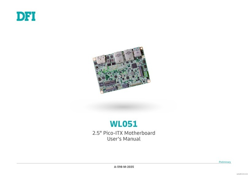
Other DFI Motherboard manuals

DFI BL631-D User manual

DFI

DFI BL631-D User manual

DFI AD73 Pro User manual

DFI

DFI AD73 Pro User manual

DFI NT70-SC User manual

DFI

DFI NT70-SC User manual

DFI AZ30-EC User manual

DFI

DFI AZ30-EC User manual

DFI KD631-C236 User manual

DFI

DFI KD631-C236 User manual

DFI 845GV-MLV User manual

DFI

DFI 845GV-MLV User manual

DFI 790fx-m2r User manual

DFI

DFI 790fx-m2r User manual

DFI WL053 User manual

DFI

DFI WL053 User manual

DFI 915G-TMGF User manual

DFI

DFI 915G-TMGF User manual

DFI P5BTX/L User manual

DFI

DFI P5BTX/L User manual

DFI BT253 User manual

DFI

DFI BT253 User manual

DFI 586ITB User manual

DFI

DFI 586ITB User manual

DFI PR610-C621 User manual

DFI

DFI PR610-C621 User manual

DFI CS35-EC User manual

DFI

DFI CS35-EC User manual

DFI 648FX-ALE User manual

DFI

DFI 648FX-ALE User manual

DFI NP951-B16C User manual

DFI

DFI NP951-B16C User manual

DFI CMS330-Q470E/H420E User manual

DFI

DFI CMS330-Q470E/H420E User manual

DFI AD75 User manual

DFI

DFI AD75 User manual

DFI CS170-Q370 User manual

DFI

DFI CS170-Q370 User manual

DFI LanParty NFII Ultra B User manual

DFI

DFI LanParty NFII Ultra B User manual

DFI SU256-SCM User manual

DFI

DFI SU256-SCM User manual

DFI WL053 User manual

DFI

DFI WL053 User manual

DFI AD77 INFINITY User manual

DFI

DFI AD77 INFINITY User manual

DFI SB331-D User manual

DFI

DFI SB331-D User manual

Popular Motherboard manuals by other brands

Intel DH61SKCH specification

Intel

Intel DH61SKCH specification

ASROCK P43DE2 user manual

ASROCK

ASROCK P43DE2 user manual

Texas Instruments DRV8300-EVM Series user guide

Texas Instruments

Texas Instruments DRV8300-EVM Series user guide

Siemens SIMATIC PG 720 manual

Siemens

Siemens SIMATIC PG 720 manual

Abit PD5NE user manual

Abit

Abit PD5NE user manual

Foxconn Cinema II Deluxe user manual

Foxconn

Foxconn Cinema II Deluxe user manual

Analog Devices DC2665B-C Demo Manual

Analog Devices

Analog Devices DC2665B-C Demo Manual

EPOX EP-5BTXA-E user manual

EPOX

EPOX EP-5BTXA-E user manual

Lattice Semiconductor EVDK user guide

Lattice Semiconductor

Lattice Semiconductor EVDK user guide

Gigabyte GA-P67A-UD7 user manual

Gigabyte

Gigabyte GA-P67A-UD7 user manual

ASROCK Rack C3758D4U-2TP user manual

ASROCK Rack

ASROCK Rack C3758D4U-2TP user manual

Asus MEB-M user manual

Asus

Asus MEB-M user manual

Gigabyte GA-X58-USB3 user manual

Gigabyte

Gigabyte GA-X58-USB3 user manual

Gigabyte Pentium II Processor 6EA product manual

Gigabyte

Gigabyte Pentium II Processor 6EA product manual

Mcube MC3479 Quick Start Guide and Demo

Mcube

Mcube MC3479 Quick Start Guide and Demo

Gigabyte GA-8VM800PMD-775-RH user manual

Gigabyte

Gigabyte GA-8VM800PMD-775-RH user manual

Gigabyte GA-945GCM-S2C user manual

Gigabyte

Gigabyte GA-945GCM-S2C user manual

Microchip Technology AT42QT1010 user guide

Microchip Technology

Microchip Technology AT42QT1010 user guide

manuals.online logo
manuals.online logoBrands
  • About & Mission
  • Contact us
  • Privacy Policy
  • Terms and Conditions

Copyright 2025 Manuals.Online. All Rights Reserved.