DFI KD171 User manual

A51200945
KD171
Mini-ITX Industrial Motherboard
User’s Manual
Preliminary
Version
Preliminary
Version

www.d.com
KD171
2
Copyright
This publication contains information that is protected by copyright. No part of it may be re-
produced in any form or by any means or used to make any transformation/adaptation without
the prior written permission from the copyright holders.
This publication is provided for informational purposes only. The manufacturer makes no
representations or warranties with respect to the contents or use of this manual and specifi-
cally disclaims any express or implied warranties of merchantability or fitness for any particular
purpose. The user will assume the entire risk of the use or the results of the use of this docu-
ment. Further, the manufacturer reserves the right to revise this publication and make changes
to its contents at any time, without obligation to notify any person or entity of such revisions
or changes.
Changes after the publication’s first release will be based on the product’s revision. The web-
site will always provide the most updated information.
© 2019. All Rights Reserved.
Trademarks
Product names or trademarks appearing in this manual are for identification purpose only and
are the properties of the respective owners.
FCC and DOC Statement on Class B
This equipment has been tested and found to comply with the limits for a Class B digital
device, pursuant to Part 15 of the FCC rules. These limits are designed to provide reason-
able protection against harmful interference when the equipment is operated in a residential
installation. This equipment generates, uses and can radiate radio frequency energy and, if not
installed and used in accordance with the instruction manual, may cause harmful interference
to radio communications. However, there is no guarantee that interference will not occur in a
particular installation. If this equipment does cause harmful interference to radio or television
reception, which can be determined by turning the equipment off and on, the user is encour-
aged to try to correct the interference by one or more of the following measures:
• Reorient or relocate the receiving antenna.
• Increase the separation between the equipment and the receiver.
• Connect the equipment into an outlet on a circuit different from that to which the re-
ceiver is connected.
• Consult the dealer or an experienced radio TV technician for help.
Notice:
1. The changes or modifications not expressly approved by the party responsible for com-
pliance could void the user’s authority to operate the equipment.
2. Shielded interface cables must be used in order to comply with the emission limits.

www.d.com
KD171
3
Table of Contents
Copyright...................................................................................................................... 2
Trademarks................................................................................................................... 2
FCC and DOC Statement on Class B............................................................................... 2
Notice: ......................................................................................................................... 2
About this Manual ......................................................................................................... 4
Warranty ..................................................................................................................... 4
Static Electricity Precautions .......................................................................................... 4
Safety Measures............................................................................................................ 4
About the Package ........................................................................................................ 5
Optional Items .............................................................................................................. 5
Before Using the System Board...................................................................................... 5
Chapter 1 - Introduction................................................................................................ 6
Specifications .......................................................................................................... 6
Features ................................................................................................................. 7
Chapter 2 - Hardware Installation .................................................................................. 8
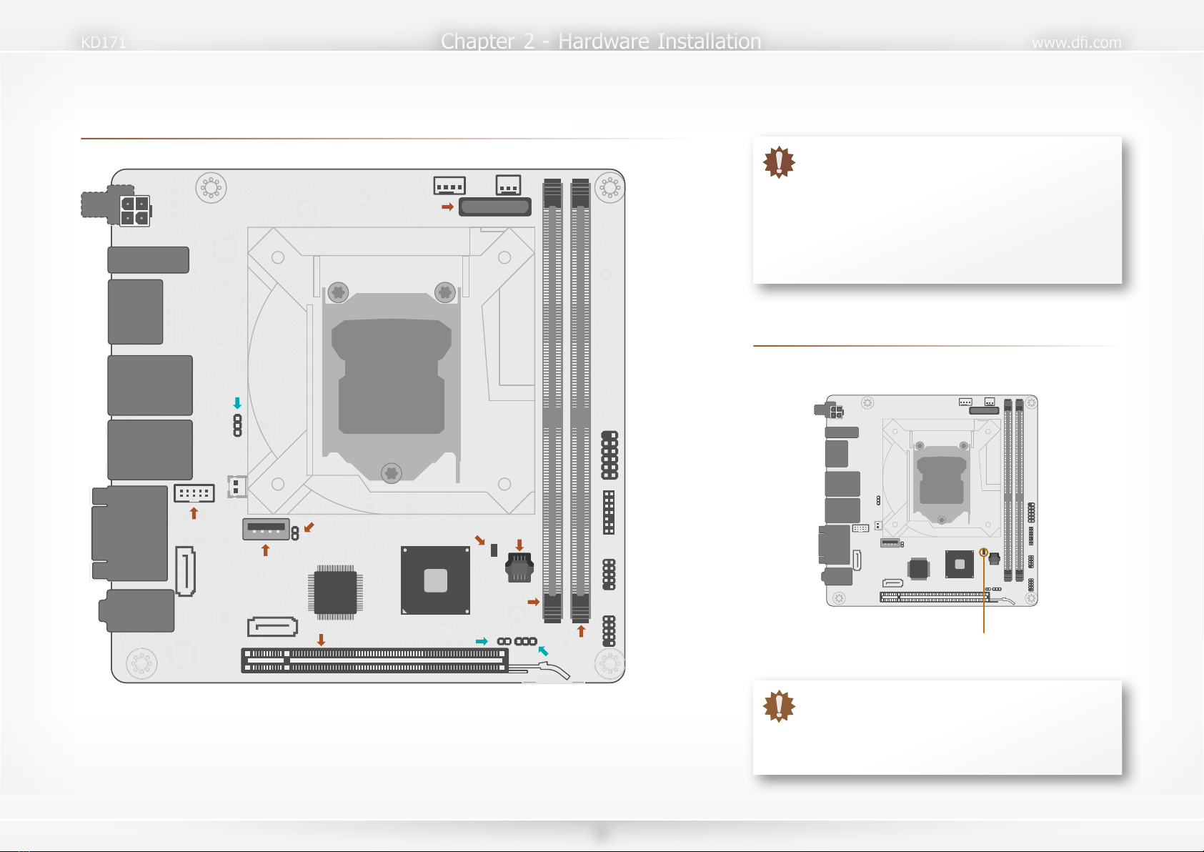
Board Layout .......................................................................................................... 8
Standby Power LED................................................................................................. 8
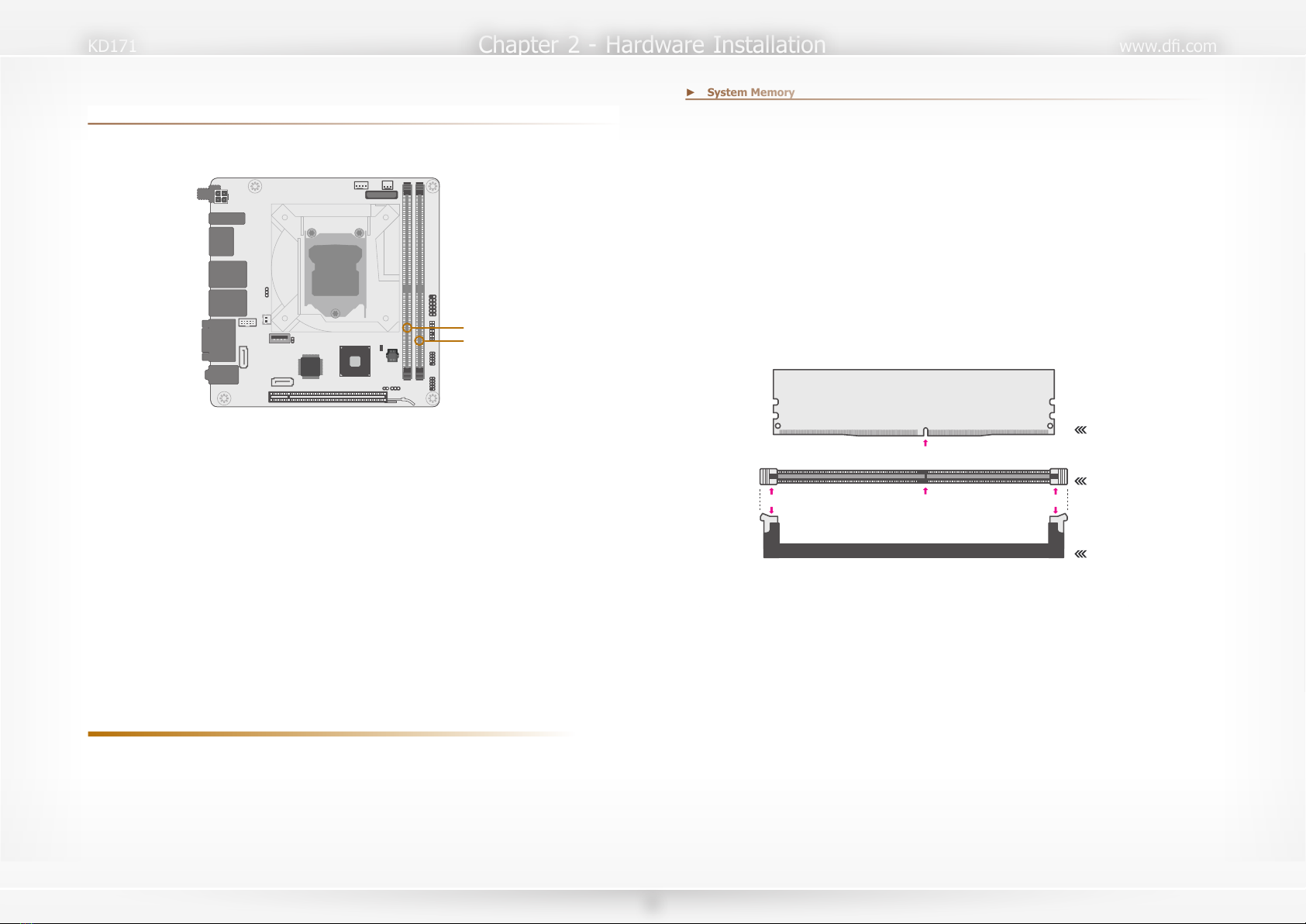
System Memory ...................................................................................................... 9
Installing the DIMM Module ............................................................................... 9
Removing the DIMM Module ............................................................................ 10
CPU...................................................................................................................... 11
Installing the CPU............................................................................................ 11
Installing the Fan and Heat Sink ...................................................................... 13
Jumper Settings .................................................................................................... 14
Clear CMOS..................................................................................................... 14
ME Disable...................................................................................................... 14
SATA1 Power Select......................................................................................... 15
Rear I/O Ports....................................................................................................... 15
12V DC In....................................................................................................... 15
Graphics Display.............................................................................................. 16
RJ45 LAN Ports ............................................................................................... 16
USB Ports ....................................................................................................... 17
COM (Serial) Ports........................................................................................... 17
Audio.............................................................................................................. 18
Internal I/O Connectors......................................................................................... 19
USB Ports ....................................................................................................... 19
Front Panel ..................................................................................................... 19
Power ............................................................................................................. 20
SATA (Serial ATA) Connectors........................................................................... 20
Cooling Fan Connectors ................................................................................... 21
LPC................................................................................................................. 21
Expansion Slots ............................................................................................... 22
Battery............................................................................................................ 22
Chapter 3 - BIOS Setup............................................................................................... 23
Overview ............................................................................................................. 23
Main ..................................................................................................................... 24
Advanced ............................................................................................................. 24
ACPI Configuration .......................................................................................... 25
CPU Configuration ........................................................................................... 26
Video Configuration ......................................................................................... 26
Audio Configuration ......................................................................................... 27
SATA Configuration .......................................................................................... 27
USB Configuration ........................................................................................... 28
PCI Express Configuration................................................................................ 28
ME Configuration............................................................................................. 29
Debug Configuration........................................................................................ 29
UEFI Device Manager ...................................................................................... 30
SIO NUVOTON6116D....................................................................................... 30
Console Redirection ......................................................................................... 32
Security ................................................................................................................ 33
Boot ..................................................................................................................... 33
Chapter 4 - Supported Software .................................................................................. 35
Auto-run Menu...................................................................................................... 35
Intel Chipset Software Installation Utility ................................................................ 35
Intel HD Graphics Drivers ..................................................................................... 36
Realtek Audio Drivers ............................................................................................ 37
Realtek LAN Driver ............................................................................................... 38
Intel ME Drivers .................................................................................................... 39
Intel Serial IO Drivers............................................................................................ 40
Adobe Acrobat Reader 9.3 ..................................................................................... 41
Intel Rapid Storage Technology ............................................................................. 42
Chapter 5 - RAID ........................................................................................................ 44
RAID Levels .......................................................................................................... 44
Setup Procedure.................................................................................................... 44

www.d.com
KD171
4
About this Manual
This manual can be downloaded from the website, or acquired as an electronic file included in
the optional CD/DVD. The manual is subject to change and update without notice, and may be
based on editions that do not resemble your actual products. Please visit our website or con-
tact our sales representatives for the latest editions.
Warranty
1. Warranty does not cover damages or failures that arised from misuse of the product,
inability to use the product, unauthorized replacement or alteration of components and
product specifications.
2. The warranty is void if the product has been subjected to physical abuse, improper
installation, modification, accidents or unauthorized repair of the product.
3. Unless otherwise instructed in this user’s manual, the user may not, under any circum-
stances, attempt to perform service, adjustments or repairs on the product, whether
in or out of warranty. It must be returned to the purchase point, factory or authorized
service agency for all such work.
4. We will not be liable for any indirect, special, incidental or consequencial damages to
the product that has been modified or altered.
Static Electricity Precautions
It is quite easy to inadvertently damage your PC, system board, components or devices even
before installing them in your system unit. Static electrical discharge can damage computer
components without causing any signs of physical damage. You must take extra care in han-
dling them to ensure against electrostatic build-up.
1. To prevent electrostatic build-up, leave the system board in its anti-static bag until you
are ready to install it.
2. Wear an antistatic wrist strap.
3. Do all preparation work on a static-free surface.
4. Hold the device only by its edges. Be careful not to touch any of the components, con-
tacts or connections.
5. Avoid touching the pins or contacts on all modules and connectors. Hold modules or
connectors by their ends.
Safety Measures
• To avoid damage to the system, use the correct AC input voltage range.
• To reduce the risk of electric shock, unplug the power cord before removing the sys-
tem chassis cover for installation or servicing. After installation or servicing, cover the
system chassis before plugging the power cord.
Important:
Electrostatic discharge (ESD) can damage your processor, disk drive and other
components. Perform the upgrade instruction procedures described at an ESD
workstation only. If such a station is not available, you can provide some ESD pro-
tection by wearing an antistatic wrist strap and attaching it to a metal part of the
system chassis. If a wrist strap is unavailable, establish and maintain contact with
the system chassis throughout any procedures requiring ESD protection.

www.d.com
KD171
5
About the Package
The package contains the following items. If any of these items are missing or damaged,
please contact your dealer or sales representative for assistance.
• One KD171 board
• One Serial ATA cable (500mm)
• One Serial ATA power cable (260mm)
• One COM port cable (300mm)
• One battery addendum
Optional Items
• USB 2.0 cable
• COM cable
• SATA cable
• I/O shield
• Thermal Solution
The board and accessories in the package may not come similar to the information listed
above. This may differ in accordance with the sales region or models in which it was sold. For
more information about the standard package in your region, please contact your dealer or
sales representative.
Before Using the System Board
Before using the system board, prepare basic system components.
If you are installing the system board in a new system, you will need at least the following
internal components.
• CPU
• Memory module
• Storage device such as hard disk drive, CD-ROM, etc.
You will also need external system peripherals you intend to use which will normally include at
least a keyboard, a mouse and a video display monitor.

www.d.com
Chapter 1 - Introduction
KD171
6
Chapter 1 - Introduction
►Specifications
SYSTEM Processor 6th/7th Generation Intel®Core™ Processors, LGA 1151 Socket
• Core™ i7-7700T Processor, Quad Core, 8M Cache, 2.9GHz (3.8GHz), 35W
• Core™ i7-7700 Processor, Quad Core, 8M Cache, 3.6GHz (4.2GHz), 65W
• Core™ i5-7500T Processor, Quad Core, 6M Cache, 2.7GHz (3.3GHz), 35W
• Core™ i5-7500 Processor, Quad Core, 6M Cache, 3.4GHz (3.8GHz), 65W
• Core™ i3-7101E Processor, Dual Core, 3M Cache, 3.9GHz , 54W
• Core™ i3-7101TE Processor, Dual Core, 3M Cache, 3.4GHz , 35W
• Celeron®G3930, Dual Core, 3M Cache, 2.9GHz, 51W
• Celeron®G3930E, Dual Core, 3M Cache, 2.9GHz, 54W
• Core™ i7-6700TE, Quad Core, 2.4GHz (3.4GHz), 35W
• Core™ i5-6500TE, Quad Core, 2.3GHz (3.3GHz), 35W
• Core™ i7-6700, Quad Core, 8M Cache, 3.4GHz (4.0GHz), 65W
• Core™ i5-6500, Quad Core, 6M Cache, 3.2GHz (3.6GHz), 65W
• Core™ i3-6100, Dual Core, 3.7GHz, 51W
• Core™ i3-6100TE, Dual Core, 2.7GHz, 35W
• Pentium®G4400, Dual Core, 3.3GHz, 54W
• Pentium®G4400TE, Dual Core, 2.4GHz, 35W
• Celeron®G3900, Dual Core, 2.8GHz, 51W
• Celeron®G3900TE, Dual Core, 2.3GHz, 35W
Chipset Intel® Q170/H110
Memory Two 288-pin UDIMM, up to 32GB, Dual Channel DDR4 2133/2400MHz
BIOS Insyde SPI
GRAPHICS Controller Intel® HD Gen 9 Graphics
Display 1 x HDMI 1.4, resolution support up to 4K @ 24Hz
2 x DP++, resolution up to 4096x2304 @ 60Hz
Feature OpenGL 5.0, DirectX 12, OpenCL 2.1
HW Decode: AVC/H.264, MPEG2, VC1/WMV9, JPEG/MJPEG, HEVC/H265, VP8,
VP9
HW Encode: MPEG2, AVC/H264, JPEG, HEVC/H265, VP8, VP9
Triple
Displays
HDMI, DP++, and DP++
EXPANSION Interface 1 x PCIe x16 (Gen 3)
ETHERNET Controller 2 x GbE (10/100/1000Mbps)
2 x Realtek®8111HN or 8119 (opt.)
REAR I/O Ethernet 2 x GbE (RJ-45)
Serial 2 x RS232 (DB9)
USB 2 x USB 3.0 Type A
2 x USB 2.0 Type A
Display 2 x Full Size DP++, 1 x HDMI 1.4 (opt.)
INTERNAL I/O Serial 4 x RS-232 (TX/RX only)
USB 1 x Vertical USB 3.0
4 x USB 2.0
SATA 2 x SATA 3.0 (up to 6Gb/s)
WATCHDOG
TIMER
Output &
Interval
System Reset, Programmable via Software from 1 to 255 Seconds
SECURITY TPM Infineon TPM2.0
Power ATX 12VDC, 2x2 pin vertical connector or coaxial connector
OS SUPPORT Microsoft Windows 10 LTSB (64 bits)
Window 7 (32/64bit) for 6th Generation Processors
Linux
ENVIRONMENT Temperature Operating: 0 to 60°C
Storage: -40 to 85°C
Humidity Operating: 5 to 90% RH
MTBF KD171-Q170: 1,454,376 hrs @ 25°C; 737,553 hrs @ 45°C ; 447,012 hrs
@ 60°C
KD171-H110: 1,454,376 hrs @ 25°C; 737,553 hrs @ 45°C ; 447,012 hrs
@ 60°C
Calculation model: Telcordia Issue 4
Environment: GB, GC – Ground Benign, Controlled
MECHANICAL Dimensions Mini-ITX Form Factor: 170mm (6.7") x 170mm (6.7")
PCB: 1.6mm

www.d.com
Chapter 1 - Introduction
KD171
7
►Features
Watchdog Timer
The Watchdog Timer function allows your application to regularly “clear” the system at the set
time interval. If the system hangs or fails to function, it will reset at the set time interval so
that your system will continue to operate.
DDR4
DDR4 delivers increased system bandwidth and improves performance. The advantages of
DDR4 provide an extended battery life and improve the performance at a lower power than
DDR3/DDR2.
Graphics
The integrated Intel®HD graphics engine delivers an excellent blend of graphics performance
and features to meet business needs. It provides excellent video and 3D graphics with out-
standing graphics responsiveness. These enhancements deliver the performance and compat-
ibility needed for today’s and tomorrow’s business applications. Supports DP++, HDMI, and
VGA interfaces for diaplay outputs.
Serial ATA
Serial ATA is a storage interface that is compliant with SATA 1.0a specification. With speed of
up to 6Gb/s (SATA 3.0), it improves hard drive performance faster than the standard parallel
ATA whose data transfer rate is 100MB/s.
Gigabit LAN
Two Realtek®8111HN PCI Express Gigabit Ethernet controllers for two individual LAN ports are
equpped to support data transmission at 1Gbps (10/100/1000Mbps).
Wake-On-LAN
This feature allows the network to remotely wake up a Soft Power Down (Soft-Off) PC. It is
supported via the onboard LAN port or via a PCI LAN card that uses the PCI PME (Power Man-
agement Event) signal. However, if your system is in the Suspend mode, you can power-on
the system only through an IRQ or DMA interrupt.
USB
The system board supports the new USB 3.0. It is capable of running at a maximum transmis-
sion speed of up to 5 Gbit/s (625 MB/s) and is faster than USB 2.0 (480 Mbit/s, or 60 MB/s)
and USB 1.1 (12Mb/s). USB 3.0 reduces the time required for data transmission, reduces
power consumption, and is backward compatible with USB 2.0. It is a marked improvement in
device transfer speeds between your computer and a wide range of simultaneously accessibl
external Plug and Play peripherals.
Wake-On-USB
This function allows you to use a USB keyboard or USB mouse to wake up a system from the
S3 (STR - Suspend To RAM) state.
RTC Timer
The RTC installed on the system board allows your system to automatically power-on on the
set date and time.
ACPI STR
The system board is designed to meet the ACPI (Advanced Configuration and Power Interface)
specification. ACPI has energy saving features that enables PCs to implement Power Manage-
ment and Plug-and-Play with operating systems that support OS Direct Power Management.
ACPI when enabled in the Power Management Setup will allow you to use the Suspend to RAM
function.
With the Suspend to RAM function enabled, you can power-off the system at once by pressing
the power button or selecting “Standby” when you shut down Windows®without having to go
through the sometimes tiresome process of closing files, applications and operating system.
This is because the system is capable of storing all programs and data files during the entire
operating session into RAM (Random Access Memory) when it powers-off. The operating ses-
sion will resume exactly where you left off the next time you power-on the system.
Power Failure Recovery
When power returns after an AC power failure, you may choose to either power-on the system
manually or let the system power-on automatically.

www.d.com
Chapter 2 - Hardware Installation
KD171
8
Chapter 2 - Hardware Installation
►Board Layout
Intel
Q170/H110
Socket LGA1151
1 2
9
1 2
9
Nuvoton
NCT6116D
1
1
Battery
Front Panel
LPC
USB 7/8
(USB 2.0)
USB 5/6
(USB 2.0)
DDR4_1
DDR4_2
J1
PCIE1 (PCIe x16)
SATA1
SATA0
COM3/4/5/6
SATA
Power
JP5
USB 3 (USB 3.0/2.0)
Chassis Intrusion
CPU FAN
DC In
Note
HDMI
DP1
DP2
LAN1
USB 1/2
(USB 3.0)
LAN2
USB 3/4
(USB 2.0)
COM1
COM2
Mic In
Line Out
Line In
SYS
FAN
SPI Flash
BIOS
Standby
LED
1
1
1413
21
2
10
JP1
1
1
1
1
10
1 9
11
Important:
When the Standby Power LED lit red, it indicates that
there is power on the system board. Power-off the PC
then unplug the power cord prior to installing any devices.
Failure to do so will cause severe damage to the mother-
board and components.
►Standby Power LED
Standby Power LED
Important:
Electrostatic discharge (ESD) can damage your board, pro-
cessor, disk drives, add-in boards, and other components.
Perform installation procedures at an ESD workstation
only. If such a station is not available, you can provide
some ESD protection by wearing an antistatic wrist strap
and attaching it to a metal part of the system chassis. If
a wrist strap is unavailable, establish and maintain contact
with the system chassis throughout any procedures requir-
ing ESD protection.

www.d.com
Chapter 2 - Hardware Installation
KD171
9
• Two 288-pin DDR4 UDIMM vertical sockets
• Supports 2133/2440 MHz DDR4 SDRAM
• Dual channel memory interface
• Supports maximum of 32GB system memory
►System Memory
Features
The system board supports the following memory interface.
Single Channel (SC)
Data will be accessed in chunks of 64 bits from the memory channels.
Dual Channel (DC)
Data will be accessed in chunks of 128 bits from the memory channels. Dual channel provides
better system performance because it doubles the data transfer rate.
Single Channel DIMMs are on the same channel. DIMMs in a channel can be identi-
cal or completely different. However, we highly recommend using
identical DIMMs. Not all slots need to be populated.
Dual Channel DIMMs of the same memory configuration are on different channels.
DDR4_1
DDR4_2
Installing the DIMM Module
Before installing the memory module, please make sure that the following safety cautions are
well-attended.
1. Make sure the PC and all other peripheral devices connected to it has been powered
down.
2. Disconnect all power cords and cables.
3. Locate the DIMM socket on the system board
4. Make sure the notch on memory card is aligned to the key on the socket.
Socket Side View
Socket Top View
DDR4 DIMM
Notch
Key
Eject TabEject Tab
Step 3
Step 2
Step 1 Step 1
Step 2
Step 3
Socket Side View
Socket Top View
DDR4 SO-DIMM
Key
Eject TabEject Tab
Step 3
Step 2
Step 1
Step 1
Step 2
Step 3
Notch
Retention Notch
►System Memory

www.d.com
Chapter 2 - Hardware Installation
KD171
10
Please follow the steps below to install the memory card into the socket.
Step 1:
Press the eject tabs at both ends of the socket outward and downward to release them from the
locked position.
Step 2:
Insert the memory card into the slot while making sure the notch and the key are aligned. Press
the card down firmly with fingers while applying and maintaining even pressure on both ends.
Step 3:
The tabs snap automatically to the edges of the card and lock the card in place.
Socket Side View
Socket Top View
DDR4 DIMM
Notch
Key
Eject TabEject Tab
Step 3
Step 2
Step 1
Step 1
Step 2
Step 3
Socket Side View
Socket Top View
DDR4 SO-DIMM
Key
Eject TabEject Tab
Step 3
Step 2
Step 1
Step 1
Step 2
Step 3
Notch
Retention Notch
Socket Side View
Socket Top View
DDR4 DIMM
Notch
Key
Eject TabEject Tab
Step 3
Step 2
Step 1
Step 1
Step 2
Step 3
Socket Side View
Socket Top View
DDR4 SO-DIMM
Key
Eject TabEject Tab
Step 3
Step 2
Step 1
Step 1
Step 2
Step 3
Notch
Retention Notch
►System Memory
►Installing the DIMM Module
Please follow the steps below to remove the memory card from the socket.
Step 1:
Press the eject tabs at both ends of the socket outward and downward to release them from the
locked position.
Step 2:
The memory card ejects from the slot automatically.
Step 3:
Hold the card by its edges and remove it from the slot.
Removing the DIMM Module
►System Memory

www.d.com
Chapter 2 - Hardware Installation
KD171
11
►CPU
The system board is equipped with a surface mount LGA 1151 socket. This socket is exclu-
sively designed for installing a LGA 1151 packaged Intel CPU.
Protective
cap
Note:
The system board used in the following illustrations may not resemble the actual
board. These illustrations and photos are for reference only.
Important:
1. Before you proceed, make sure (1) the LGA 1151 socket comes with a protec-
tive cap, (2) the cap is not damaged and (3) the socket’s contact pins are not
bent. If the cap is missing or the cap and/or contact pins are damaged, contact
your dealer immediately.
2. Make sure to keep the protective cap. RMA requests will be accepted and pro-
cessed only if the LGA 1151 socket comes with the protective cap.
Installing the CPU
1. Make sure the PC and all other peripheral devices connected to it have been powered
down.
2. Disconnect all power cords and cables.
3. Locate the LGA 1151 CPU
socket on the system board.
4. Unlock the socket by pressing
the load lever down, moving
it sideways until to escape the
retention tab. Lift the load lever
up when it’s released.
Retention tab
Load lever
Important:
The CPU socket must not come in contact with anything other than the CPU. Avoid
unnecessary exposure. Remove the protective cap only when you are about to in-
stall the CPU.

www.d.com
Chapter 2 - Hardware Installation
KD171
12
6. Remove the protective cap from
the CPU socket. The cap is used
to protect the CPU socket against
dust and harmful particles. Re-
move the protective cap only
when you are about to install the
CPU.
5. Lift the load lever and the load
plate all the way up as shown in
the photo.
Load lever
Load
plate
Protective cap
7-1.Insert the CPU into
the socket. The gold
triangular mark on the
CPU must align with
the chamfer corner of
the CPU socket shown
in the photo.
Golden triangular
mark
►CPU
►Installing the CPU
Important:
The CPU will fit in only one orientation and can easily be seated without exerting
any force.
7-2.Two keys on the sock-
et and notches on
the CPU also facilitate
alignment.
7-3.The CPU’s notch will
fit into the socket’s
alignment key when
it’s seated in the cor-
rect orientation.
Alignment key
Alignment key
►CPU
►Installing the CPU
8. Close the load plate
then push the load le-
ver down.
While closing the load
plate, make sure the
front edge of the load
plate slides under the
retention knob.
9. Press down the load
lever and hook it un-
der the retention tab.
Retention knob
Load lever

www.d.com
Chapter 2 - Hardware Installation
KD171
13
Installing the Fan and Heat Sink
The CPU must be kept cool by using a CPU fan with heat sink. Without sufficient air circula-
tion across the CPU and heat sink, the CPU will overheat damaging both the CPU and system
board.
1. Before you install the fan / heat sink, you must apply a thermal paste onto the top of
the CPU. The thermal paste is usually supplied when you purchase the fan / heat sink
assembly. Do not spread the paste all over the surface. When you later place the heat
sink on top of the CPU, the compound will disperse evenly.
Some heat sinks come with a patch of pre-applied thermal paste. Do not apply thermal
paste if the fan / heat sink already has a patch of thermal paste on its underside. Peel
the strip that covers the paste before you place the fan / heat sink on top of the CPU.
2. Place the heat sink on top of the CPU. The 4 spring screws around the heat sink,
which are used to secure the heat sink onto the system board, must match the 4
mounting holes around the socket.
3. Orient the heat sink so that the CPU fan’s cable is nearest the CPU fan connector.
►CPU
4. Screw tight two of the spring screws at opposite corners into the mounting holes. And
then proceed with the other two spring screws.
Heat sink
“Locked” position of
push-pin
5. Connect the CPU fan’s cable to the CPU fan connector on the system board.
“Unlocked” position
of push-pin
Note:
A boxed Intel®processor already includes the CPU fan and heat sink assembly. If
your CPU was purchased separately, make sure to only use Intel®-certified fan and
heat sink.
Mounting
holes
CPU fan
connector

www.d.com
Chapter 2 - Hardware Installation
KD171
14
►Jumper Settings
Clear CMOS
JP1 J1
If any anomaly of the followings is encountered —
a) CMOS data is corrupted;
b) you forgot the supervisor or user password;
c) failure to start the system due to BIOS mis-configuration
— it is suggested that the system be reconfigured with default values stored in the ROM BIOS.
To load the default values stored in the ROM BIOS, please follow the steps below.
1. Power-off the system and unplug the power cord.
2. Put a jumper cap on JP9’s pin 2 and pin 3. Wait for a few seconds and set JP9 back to
its default setting, i.e. jumper cap on pin 1 and pin 2.
3. Plug the power cord and power-on the system.
The 2-pin jack J1 is used to enable or disable Management Engine (ME). Put on a jumper cap
to disable ME (default), or remove the jumper to enable ME.
ME Disable
▲2-3 On: Clear CMOS▲1-2 On: Normal (default)
1 13 32 2

www.d.com
Chapter 2 - Hardware Installation
KD171
15
SATA1 Power Select
▲2-3 On: SATA DOM▲1-2 On: Normal SATA (default)
SATA1 supports power supply via power cable or Disk on Module (DOM) to which power is
supplied via Pin 7. To switch between the power supply mode, please configure the jumper
settings as illustrated below.
3 3
1 1
2 2
JP5
SATA1

www.d.com
Chapter 2 - Hardware Installation
KD171
15
►Rear I/O Ports
The rear panel I/O ports consist of the following:
• DC In (optional)
• 1 x HDMI 1.4
• 2 x DP++
• 2 x USB 3.0
• 2 x USB 2.0
• 2 x GbE (RJ-45)
• 2 x RS-232 (DB-9)
• Mic In, Audio Line In, and Audio Line Out
▲COM 2▲DP++▲DC In
▲DC In coaxial
▲Audio
▼LAN 1 ▼LAN 2 ▼COM 1▼HDMI
▲USB 3.0 ▲USB 2.0
Note:
The DC power jack can be a rear coaxial connector or an internal 2x2 pin vertical
connector.
Connect a coaxial DC power cord to the rear coaxial connector for DC supply. Using a voltage
higher than the recommended range may result in failure in starting and booting the system
or causing irreversible damage to the system board. A power adaptor/converter is necessary
when the power source on site does not comply with the power specifications of the board.
DC In coaxial (optional)
4-pin Vertical Type
12V DC In

www.d.com
Chapter 2 - Hardware Installation
KD171
16
Graphics Display
DP++
The DisplayPort is a digital display interface used to connect a display device such as a com-
puter monitor. It is used to transmit audio and video simultaneously. The interface, which is
developed by VESA, delivers higher performance features than any other digital interface.
HDMI 1.4
The HDMI port which carries both digital audio and video signals is used to connect a LCD
monitor or digital TV that has the HDMI port.
BIOS Setting
Configure VGA in the Advanced menu (“Video Configuration” submenu) of the BIOS. Refer to
Chapter 3 for more information.
Driver Installation
Install the graphics driver. Refer to Chapter 4 for more information.
▲DP++▲HDMI
RJ45 LAN Ports
The LAN ports allow the system board to connect to a local area network by means of a net-
work hub.
BIOS Setting
Configure the onboard LAN in the Advanced menu (“PCI Express Configuration” submenu) of
the BIOS. Refer to chapter 3 for more information.
Driver Installation
Install the LAN drivers. Refer to chapter 4 for more information.
Features
• LAN 1/2: Realtek®8111HN (81119 by request) PCIe GbE Controller
►Rear I/O Ports
▼LAN 1 ▼LAN 2
►Rear I/O Ports

www.d.com
Chapter 2 - Hardware Installation
KD171
17
USB Ports
USB allows data exchange between your computer and a wide range of simultaneously acces-
sible external Plug and Play peripherals. The system board is equipped with two onboard USB
3.0 ports (USB 1&2) at the rear side. For the internal USB 3.0 and 2.0 ports, please refer to
the next section.
BIOS Setting
Configure the onboard USB in the Advanced menu (“USB Configuration” submenu) of the
BIOS. Refer to chapter 3 for more information.
Wake-On-USB Keyboard/Mouse
The Wake-On-USB Keyboard/Mouse function allows you to use a USB keyboard or USB mouse
to wake up a system from the S3 (STR - Suspend To RAM) state.
▲USB 3.0 ▲USB 2.0
►Rear I/O Ports
COM (Serial) Ports
►Rear I/O Ports
The serial ports are asynchronous communication ports with 16C550A-compatible UARTs that
can be used with modems, serial printers, remote display terminals, and other serial devices.
COM 1 and COM 2 (Rear Ports) support only RS232. COM 3 - COM 6 (Internal Ports) support
RS232 with only RX and TX signals as addressed later in this chapter.
BIOS Setting
Configure the onboard COM ports in the Advanced menu (“Console Redirection” submenu) of
the BIOS. Refer to chapter 3 for more information.
◄ COM 2
◄ COM 1
Pin RS232
1DCD-
2RD
3TD
4DTR-
5GND
6DSR-
7RTS-
8CTS-
9RI-
▼COM 1/2 Pin Assignment

www.d.com
Chapter 2 - Hardware Installation
KD171
18
Audio
►Rear I/O Ports
The system board is equipped a rear stacked audio jacks.
• Line-in Jack (Light Blue)
This jack is used to connect any audio devices such as Hi-fi set, CD player, tape player,
AM/FM radio tuner, synthesizer, etc.
• Line-out Jack (Lime)
This jack is used to connect a headphone or external speakers.
• Mic-in Jack (Pink)
This jack is used to connect an external microphone.
Driver Installation
Install the audio driver. Refer to Chapter 4 for more information.
Line-out
Line-in
Mic-in

www.d.com
Chapter 2 - Hardware Installation
KD171
19
►Internal I/O Connectors
USB Ports
The USB device allows data exchange between your computer and a wide range of simultane-
ously accessible external Plug and Play peripherals.
In addition to the rear USB ports as introduced previously in this chapter, the system board is
equipped with an internal USB 3.0 and USB 2.0 ports as illustrated above.
The internal USB pin headers may be connected to a card-edge bracket. Install the card-edge
bracket to an available slot at the rear of the system chassis and then insert the USB port
cables to a connector.
BIOS Setting
Configure the onboard USB in the Advanced menu (“USB Configuration” submenu) of the
BIOS. Refer to chapter 3 for more information.
Wake-On-USB Keyboard/Mouse
The Wake-On-USB Keyboard/Mouse function allows you to use a USB keyboard or USB mouse
to wake up a system from the S state(s).
▼USB 2.0
Pin Assignment
▲USB 3
(USB 3.0 Type A)
▼USB 7/8 (upper) 5/6
(lower), USB 2.0
1 4
VCC
-Data
+Data
GND
Key
VCC
-Data
+Data
GND
N.C.
2
10
1
1 2
10
▲Front Panel Connector
HD-LED
RESET
PWR-LED
ATX-SW
2 1
1112
HDD-LED - Hard Disk Drive LED
Lighting of the LED indicates that the hard drive is being accessed.
RESET - Reset Switch
This switch allows you to reboot without having to power off the system.
PWR-LED - Power/Standby LED
When the system’s power is on, this LED will light up. When the system is in the S1 (POS
- Power On Suspend) state, it will blink at 1-second intervals. When the system is in the S3
(STR - Suspend To RAM) state, it will blink at 4-second intervals.
ATX-SW - ATX Power Switch
This switch is used to power on or off the system.
▼Front Panel Pin Assignment
Pin Assignment Pin Assignment
1N.C.
PWR-LED
2LED Power
HD-LED
3HDD Power 4LED Power
5Signal 6Signal
RESET
7Ground
ATX-SW
8Ground
9Signal 10 Signal
11 N.C. 12 ---
Front Panel
►Internal I/O Connectors
Table of contents
Other DFI Motherboard manuals