DFI PL610-C622 User manual

1
PL610-C622
ATX Industrial Motherboard
User’s Manual
A48100840
Preliminary
Version

2
Copyright
This publication contains information that is protected by copyright. No part of it may be re-
produced in any form or by any means or used to make any transformation/adaptation without
the prior written permission from the copyright holders.
This publication is provided for informational purposes only. The manufacturer makes no
representations or warranties with respect to the contents or use of this manual and specifi-
cally disclaims any express or implied warranties of merchantability or fitness for any particular
purpose. The user will assume the entire risk of the use or the results of the use of this docu-
ment. Further, the manufacturer reserves the right to revise this publication and make changes
to its contents at any time, without obligation to notify any person or entity of such revisions
or changes.
Changes after the publication’s first release will be based on the product’s revision. The website
will always provide the most updated information.
© 2018. All Rights Reserved.
Trademarks
Product names or trademarks appearing in this manual are for identification purpose only and
are the properties of the respective owners.
FCC and DOC Statement on Class B
This equipment has been tested and found to comply with the limits for a Class B digital
device, pursuant to Part 15 of the FCC rules. These limits are designed to provide reason-
able protection against harmful interference when the equipment is operated in a residential
installation. This equipment generates, uses and can radiate radio frequency energy and, if not
installed and used in accordance with the instruction manual, may cause harmful interference
to radio communications. However, there is no guarantee that interference will not occur in a
particular installation. If this equipment does cause harmful interference to radio or television
reception, which can be determined by turning the equipment off and on, the user is encour-
aged to try to correct the interference by one or more of the following measures:
• Reorient or relocate the receiving antenna.
• Increase the separation between the equipment and the receiver.
• Connect the equipment into an outlet on a circuit different from that to which the receiver
is connected.
• Consult the dealer or an experienced radio TV technician for help.
Notice:
1. The changes or modifications not expressly approved by the party responsible for compli-
ance could void the user’s authority to operate the equipment.
2. Shielded interface cables must be used in order to comply with the emission limits.

3
Table of Contents
Copyright..........................................2
Trademarks.......................................2
FCC and DOC Statement on Class B ..2
Warranty ..........................................4
Static Electricity Precautions .............. 4
Safety Measures................................4
About the Package............................ 5
Chapter 1 - Introduction....................6
Specifications...........................................................................6
Features..................................................................................7
Chapter 2 - Hardware Installation ...... 9
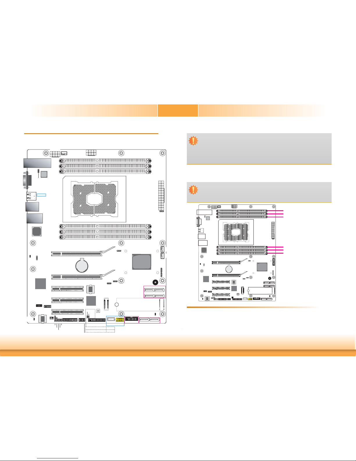
Board Layout...........................................................................9
System Memory.......................................................................9
Installing the DIMM Module ....................................................... 10
CPU ...................................................................................... 11
Installing the CPU, Fan and Heat Sink ........................................ 12
Jumper Settings..................................................................... 14
BMC/PCH SMB Host Select ........................................................ 14
Clear CMOS............................................................................. 14
Flash Security Override............................................................. 15
PCIe 3 Switch.......................................................................... 15
Enable eSPI............................................................................. 16
UART Debug Select .................................................................. 16
Rear Panel I/O Ports.............................................................. 17
Graphics Interface.................................................................... 17
LAN Ports................................................................................ 18
USB Ports................................................................................ 18
I/O Connectors ...................................................................... 20
SATA (Serial ATA) Connectors .................................................... 20
BMC JTAG Female Connector ..................................................... 20
Cooling Fan Connectors............................................................. 21
Power Connectors .................................................................... 21
Front Panel Connector .............................................................. 22
LEDs....................................................................................... 23
Expansion Slots ....................................................................... 23
PLD Update Connector .............................................................. 24
Battery ................................................................................... 24
SMBus Connector ..................................................................... 25
COM (Serial) Ports ................................................................... 25
LPC Debug Connector ............................................................... 26
Switch .................................................................................... 26
PHY I2C SDA/SCL 1P8V Debug Connector ................................... 27
Clock Gen Clock Ref Connector .................................................. 27
Chapter 3 - BIOS Setup...............................28
Overview .............................................................................. 28
Insyde BIOS Setup Utility....................................................... 29
Main ....................................................................................... 29
Advanced ............................................................................... 29
Security .................................................................................. 42
Boot ....................................................................................... 43
Exit ........................................................................................ 44
Updating the BIOS................................................................. 44
Notice: BIOS SPI ROM ........................................................... 45
Chapter 4 - Supported Software....................46
Chapter 5 - RAID.........................................52

4
Warranty
1. Warranty does not cover damages or failures that arised from misuse of the product,
inability to use the product, unauthorized replacement or alteration of components and
product specifications.
2. The warranty is void if the product has been subjected to physical abuse, improper instal-
lation, modification, accidents or unauthorized repair of the product.
3. Unless otherwise instructed in this user’s manual, the user may not, under any circum-
stances, attempt to perform service, adjustments or repairs on the product, whether in or
out of warranty. It must be returned to the purchase point, factory or authorized service
agency for all such work.
4. We will not be liable for any indirect, special, incidental or consequencial damages to the
product that has been modified or altered.
Static Electricity Precautions
It is quite easy to inadvertently damage your PC, system board, components or devices even
before installing them in your system unit. Static electrical discharge can damage computer
components without causing any signs of physical damage. You must take extra care in han-
dling them to ensure against electrostatic build-up.
1. To prevent electrostatic build-up, leave the system board in its anti-static bag until you are
ready to install it.
2. Wear an antistatic wrist strap.
3. Do all preparation work on a static-free surface.
4. Hold the device only by its edges. Be careful not to touch any of the components, contacts
or connections.
5. Avoid touching the pins or contacts on all modules and connectors. Hold modules or con-
nectors by their ends.
Safety Measures
To avoid damage to the system:
• Use the correct AC input voltage range.
To reduce the risk of electric shock:
• Unplug the power cord before removing the system chassis cover for installa-
tion or servicing. After installation or servicing, cover the system chassis before
plugging the power cord.
Important:
Electrostatic discharge (ESD) can damage your processor, disk drive and other com-
ponents. Perform the upgrade instruction procedures described at an ESD worksta-
tion only. If such a station is not available, you can provide some ESD protection by
wearing an antistatic wrist strap and attaching it to a metal part of the system chas-
sis. If a wrist strap is unavailable, establish and maintain contact with the system
chassis throughout any procedures requiring ESD protection.

5
About the Package
The package contains the following items. If any of these items are missing or damaged,
please contact your dealer or sales representative for assistance.
• One PL610-C622 motherboard
• One COM port cable (Length: 400mm, 2 x COM ports)
• One Serial ATA data cable (Length: 500mm)
• One I/O shield
The board and accessories in the package may not come similar to the information listed
above. This may differ in accordance to the sales region or models in which it was sold. For
more information about the standard package in your region, please contact your dealer or
sales representative.
Optional Items
• USB port cable (Length: 398mm)
The board and accessories in the package may not come similar to the information listed
above. This may differ in accordance to the sales region or models in which it was sold. For
more information about the standard package in your region, please contact your dealer or
sales representative.
Before Using the System Board
Before using the system board, prepare basic system components.
If you are installing the system board in a new system, you will need at least the following
internal components.
• A CPU
• Memory module
• Storage devices such as hard disk drive, etc.
You will also need external system peripherals you intend to use which will normally include at
least a keyboard, a mouse and a video display monitor.

6
Chapter 1 - Introduction
Specifications
Chapter 1
Chapter 1 Introduction www.dfi.com
SYSTEM Processor Intel®Xeon®Scalable Processor Family, LGA 3647 Socket
Chipset Intel®C622 Chipset
Memory Six 288-pin RDIMM up to 192GB
Single Channel DDR4 1600/1866/2133/2400/2666MHz
BIOS Insyde SPI 128Mbit
GRAPHICS Display 1 x VGA
Single
Display
VGA
EXPANSION Interface 2 x PCIe x16 (Gen 3)
1 x PCIe x8 (Gen 3)
2 x PCIe x4 (Gen 3)
1 x M.2 2280 M key (PCIe Gen3 x 4 NVMe)
AUDIO
Audio
Codec
N/A
ETHERNET Controller GbE: i350-AM2
10GbE: CS4227
IPMI: RTL8211F
REAR I/O Ethernet 2 x GbE (RJ-45)
1 x dedicated IPMI LAN
1 x Fiber 10 GbE
USB 2 x USB 2.0
PS/2 1 x PS/2 (mini-DIN-6)
Display 1 x VGA
INTERNAL I/O Serial 1 x RS-232 (2.54mm pitch)
USB 2 x USB 2.0 (2.54mm pitch)
1 x Vertical USB 2.0
2 x USB 3.0
SATA 6 x SATA 3.0 (up to 6Gb/s)
WATCHDOG
TIMER
Output &
Interval
System Reset, Programmable via Software from 1 to 255 Seconds
SECURITY TPM Infineon TPM 2.0 (optional)
POWER Type ATX
Connector 8-pin ATX 12V power
24-pin ATX power
Consumption TBD
RTC Battery CR2032 Coin Cell
OS SUPPORT Windows 10 IoT Enterprise LTSB RS1 (64-bit)
Windows Server 2012R2
Windows Server 2016
Ubuntu16.04
ENVIRONMENT Temperature Operating: 0 to 60°C
Storage: -30 to 60°C with RTC Battery; -40 to 85°C without RTC Battery
Humidity Operating: 5 to 90% RH
Storage: 5 to 90% RH
MTBF TBD
MECHANICAL Dimensions ATX Form Factor
305mm (12") x 244mm (9.6")
Height PCB: TBD
Top Side: TBD
Bottom Side: TBD

7
Chapter 1
Features
• Watchdog Timer
The Watchdog Timer function allows your application to regularly “clear” the system at the set
time interval. If the system hangs or fails to function, it will reset at the set time interval so
that your system will continue to operate.
• DDR4
DDR4 deliver increased system bandwidth and improved performance. The advantages of
DDR4 are its higher bandwidth and its increase in performance at a lower power than DDR3/
DDR3L/DDR2. It is not compatible with DDR3/DDR3L/DDR2.
• PCI Express
PCI Express is a high bandwidth I/O infrastructure that possesses the ability to scale speeds
by forming multiple lanes. The x4 PCI Express lane supports transfer rate of 4 Gigabyte per
second (2 directions). The PCI Express architecture also supports high performance graphics
infrastructure by enhancing the capability of a PCIe x16 Gen 3 at 16GB/s bandwidth (8GB/s in
each direction).
• Serial ATA
Serial ATA is a storage interface that is compliant with SATA 1.0a specification. With speed of
up to 6Gb/s (SATA 3.0), it improves hard drive performance faster than the standard parallel
ATA whose data transfer rate is 100MB/s. The bandwidth of the SATA 3.0 will be limited by
carrier board design.
• Wake-On-PS/2
This function allows you to use the PS/2 keyboard or PS/2 mouse to power-on the system.
Important:
The 5V_standby power source of your power supply must support ≥720mA.
• Wake-On-USB
This function allows you to use a USB keyboard or USB mouse to wake up a system from the
S3 (STR - Suspend To RAM) state.
• RTC Timer
The RTC installed on the system board allows your system to automatically power-on on the
set date and time.
• ACPI STR
The system board is designed to meet the ACPI (Advanced Configuration and Power Interface)
specification. ACPI has energy saving features that enables PCs to implement Power Manage-
ment and Plug-and-Play with operating systems that support OS Direct Power Management.
ACPI when enabled in the Power Management Setup will allow you to use the Suspend to RAM
function.
With the Suspend to RAM function enabled, you can power-off the system at once by pressing
the power button or selecting “Standby” when you shut down Windows®without having to go
through the sometimes tiresome process of closing files, applications and operating system.
This is because the system is capable of storing all programs and data files during the entire
operating session into RAM (Random Access Memory) when it powers-off. The operating ses-
sion will resume exactly where you left off the next time you power-on the system.
Important:
If you are using the Wake-On-USB Keyboard/Mouse function for 2 USB ports, the
5V_standby power source of your power supply must support ≥1.5A. For 3 or more
USB ports, the 5V_standby power source of your power supply must support ≥2A.
• Wake-On-LAN
This feature allows the network to remotely wake up a Soft Power Down (Soft-Off) PC. It
is supported via the onboard LAN port or via a PCI LAN card that uses the PCI PME (Power
Management Event) signal. However, if your system is in the Suspend mode, you can power-
on the system only through an IRQ or DMA interrupt.
Important:
The 5V_standby power source of your power supply must support ≥720mA.
Chapter 1 Introduction www.dfi.com
Important:
The 5V_standby power source of your power supply must support ≥720mA.

8
• Power Failure Recovery
When power returns after an AC power failure, you may choose to either power-on the system
manually or let the system power-on automatically.
• USB
The system board supports the new USB 3.0. It is capable of running at a maximum transmis-
sion speed of up to 5 Gbit/s (625 MB/s) and is faster than USB 2.0 (480 Mbit/s, or 60 MB/s)
and USB 1.1 (12Mb/s). USB 3.0 reduces the time required for data transmission, reduces
power consumption, and is backward compatible with USB 2.0. It is a marked improvement in
device transfer speeds between your computer and a wide range of simultaneously accessible
external Plug and Play peripherals.
Chapter 1
Chapter 1 Introduction www.dfi.com

www.dfi.com
9
Chapter 2 Hardware Installation
Chapter 2
Chapter 2 - Hardware Installation
Board Layout
M.2 M Key
USB 2.0
Socket LGA3647
10
9
19
USB 4-5
2
10
DDR4_3
DDR4_2
DDR4_1
ATX Power
2
119
20
LPC
Debug
SATA 0
SATA 5
SATA 3.0
1
SATA 2
1
SATA 1
SATA 3.0
SATA 4
SATA 3
COM Port C from
PCH’s IE HSUART
+12V
Power
4
81
5
5
8
CPU Fan
1 4
113
12 24
13
CPU & DIMM
Power IC
Update
1
4
1
4
System
Fan 1
System
Fan 2
1
Buzzer
10GLAN
VGA
USB 1-2
MNG
GLAN
DDR4_4
DDR4_5
DDR4_6
Intel
C622
1 1
1 1
110
11
20 USB 5-6
USB 3.0
USB 3
1
4
USB 2.0
1
224
23
Front Panel
1
2
7
8
PLD Update
BMC JTAG
1111
5
1
6
2
SMBus
BMC UART5 UART Debug Select (JP2)
Enable eSPI (J14)
BMC Password Clear
BMC SPI
2
111
12
1
2
9
10
COM 1
Battery
Battery
PCIe5 (PCIe x4)
PCIe3 (PCIe x4)
PCIe4 (PCIe x8)
XDP
BMC Reset
Button
LED 10
LED 9
CONT Stat GRN
CONT Stat Amber
LED9
LED10
Inphi
CS4227
ASPEED
AST2500
Intel
I350AM2
LATTICE
LCMXO2
SPI Flash BIOS
PCIe 2 (PCIe x16)
PCIe 1 (PCIe x16)
I350 PE Wake LED
1
PHY I2C
SDA/SCL
1P8V Debug
11
Clock Gen
Clock Ref
1
PCIe SW
(JP14)
Flash
Security
Override
(JP8)
14
+12V
Power
BMC
Heartbeat
LED
1
BMC/PCH SMB Host Select
(JP16)
11
Clear CMOS (JP15)
1
1
RSVD CPLD UPDATE (JP11)
SATA LED
10
9
Battery
System Memory
Features
Important:
Electrostatic discharge (ESD) can damage your board, processor, disk drives, add-in
boards, and other components. Perform installation procedures at an ESD workstation
only. If such a station is not available, you can provide some ESD protection by wear-
ing an antistatic wrist strap and attaching it to a metal part of the system chassis. If
a wrist strap is unavailable, establish and maintain contact with the system chassis
throughout any procedures requiring ESD protection.
Important:
When the Standby Power LED lit red, it indicates that there is power on the system
board. Power-off the PC then unplug the power cord prior to installing any devices.
Failure to do so will cause severe damage to the motherboard and components.
DDR4_2
DDR4_1
DDR4_3
• Six 288-pin RDIMM up to 192GB
• Single Channel DDR4 1600/1866/2133/2400/2666 MHz
DDR4_5
DDR4_6
DDR4_4

www.dfi.com
10
Chapter 2 Hardware Installation
Chapter 2
The system board supports the following memory interface.
Single Channel (SC)
Data will be accessed in chunks of 64 bits (8B) from the memory channels.
Dual Channel (DC)
Data will be accessed in chunks of 128 bits from the memory channels. Dual channel provides
better system performance because it doubles the data transfer rate.
Installing the DIMM Module
Single Channel
DIMMs are on the same channel.
DIMMs in a channel can be identical or
completely different. However, we highly
recommend using identical DIMMs.
Not all slots need to be populated.
Dual Channel DIMMs of the same memory configuration
are on different channels.
Note:
The system board used in the following illustrations may not resemble the actual
board. These illustrations are for reference only.
1. Make sure the PC and all other peripheral devices connected to it has been powered down.
2. Disconnect all power cords and cables.
3. Locate the DIMM socket on the system board.
4. Push the “ejector tabs” at the ends of the socket to the side.
Ejector tab
Ejector tab
5. Note how the module is keyed to the socket.
Key
Notch

www.dfi.com
11
Chapter 2 Hardware Installation
Chapter 2
CPU
The system board is equipped with a surface mount LGA 3647 socket. This socket is exclu-
sively designed for installing a LGA 3647 packaged Intel CPU.
Protective
cap
Important:
1. Before you proceed, make sure (1) the LGA 3647 socket comes with 2 protective
caps, (2) the caps are not damaged and (3) the socket’s contact pins are not bent.
If the caps are missing or the caps and/or contact pins are damaged, contact your
dealer immediately.
2. Make sure to keep the protective caps. RMA requests will be accepted and pro-
cessed only if the LGA 3647 socket comes with the protective caps.
7. Seat the module vertically, pressing it down firmly until it is completely seated in the
socket.
6. Grasping the module by its edges, position the module above the socket with the “notch”
in the module aligned with the “key” on the socket. The keying mechanism ensures the
module can be plugged into the socket in only one way.
8. The ejector tabs at the ends of the socket will automatically snap into the locked position
to hold the module in place.
Protective
cap

www.dfi.com
12
Chapter 2 Hardware Installation
Chapter 2
Installing the CPU, Fan and Heat Sink
The CPU must be kept cool by using a CPU fan with heat sink. Without sufficient air circula-
tion across the CPU and heat sink, the CPU will overheat damaging both the CPU and system
board.
1. Before you place the CPU on the heat sink, you must apply a thermal paste onto the top
of the heat sink. The thermal paste is usually supplied when you purchase the fan with
heat sink assembly. Do not spread the paste all over the surface. When you later place the
CPU on top of the heat sink, the compound will disperse evenly.
Some heat sinks come with a patch of pre-applied thermal paste. Do not apply thermal
paste if the fan with heat sink already has a patch of thermal paste on its underside. Peel
the strip that covers the paste before you place the CPU on top of the heat sink.
Note:
A boxed Intel®processor already includes the CPU fan and heat sink assembly. If your
CPU was purchased separately, make sure to only use Intel®-certified fan and heat
sink.
2. Insert the CPU into the
CPU carrier. The gold
triangular mark on the CPU
must align with the corner
of the CPU carrier shown
on the photo.
Gold triangular mark
3. Place the CPU carrier on
top of the heat sink. Place
the triangular hole near
the mounting hole #1 of
the heat sink. Use the
push-pins around the CPU
carrier to secure the CPU
carrier onto the heat sink.
You will hear a distinctive
“click”, indicating the CPU
carrier is correctly locked
into position.
Triangular hole
Mounting hole #1 of
the heat sink
Mounting hole #1
Triangular hole
4. Slide the protective caps
and remove them from the
board.

www.dfi.com
13
Chapter 2 Hardware Installation
Chapter 2
5. Place the fan / heat
sink assembly on top of
the socket. Use the T30
screwdriver to install the
assembly according to the
sequence of the screws
shown on the label.
6. Connect the CPU fan’s
cable to the CPU fan
connector on the system
board.

www.dfi.com
14
Chapter 2 Hardware Installation
Chapter 2
Jumper Settings
BMC/PCH SMB Host Select
10
9
Battery
JP16
JP16 is used to select SMB host: BMC or PCH.
1
3
2
1
3
2
1-2 On:
BMC SMB Host (default)
2-3 On:
PCH SMB Host
Clear CMOS
10
9
Battery
JP15
If you encounter the followings,
a) CMOS data becomes corrupted.
b) You forgot the supervisor or user password.
you can reconfigure the system with the default values stored in the ROM BIOS.
To load the default values stored in the ROM BIOS, please follow the steps below.
1. Power-off the system and unplug the power cord.
2. Set JP15 pins 2 and 3 to On. Wait for a few seconds and set JP15 back to its default set-
ting,
pins 1 and 2 On.
3. Now plug the power cord and power-on the system.
132
132
1-2 On:
Normal (default)
2-3 On:
Clear RTC Registers

www.dfi.com
15
Chapter 2 Hardware Installation
Chapter 2
Flash Security Override
10
9
Battery
JP8
JP8 is used to enable or disable flash security override.
1
3
2
1
3
2
1-2 On:
Disable (default)
2-3 On: Enable
PCIe 3 Switch
10
9
Battery
JP14
JP14 is used to select PCIe 3: Riser 3 or 10G.
When JP14 is set to 1-2 on and “On board 10G LAN” field of the BIOS is set to disabled,
onboard 10G LAN is not supported and PCIe3 has full x8 function. When JP14 is set to 2-3 on
and “On board 10G LAN” field of the BIOS is set to enabled, half lanes of PCIe3 are used for
onboard 10G LAN (PCH uplink) and PCIe3 only has x4 function.
2-3 On:
10G
1-2 On:
Riser 3 (default)
312
312

www.dfi.com
16
Chapter 2 Hardware Installation
Chapter 2
Enable eSPI
10
9
Battery
J14
J14 is used to enable eSPI or LPC mode.
1
2
1
2
0 On:
LPC Mode (default)
1 On:
eSPI Mode
UART Debug Select
10
9
Battery
JP2
JP2 is used to select UART1 or UART5 as BMC Console Port.
1
2
1
2
0 On:
UART1 as
BMC Console Port
(default)
1 On:
UART5 as
BMC Console Port

www.dfi.com
17
Chapter 2 Hardware Installation
Chapter 2
Rear Panel I/O Ports
The rear panel I/O ports consist of the following:
• 1 10GLAN
• 1 VGA port
• 2 USB 2.0 ports
• 1 MNG port
• 2 GLAN ports
10GLAN GLANMNG
VGA USB 2.0
Graphics Interface
The display port consists of the following:
• 1 VGA port
10
9
Battery
VGA
VGA Port
The VGA port is used for connecting a VGA monitor. Connect the monitor’s 15-pin D-shell cable
connector to the VGA port. After you plug the monitor’s cable connector into the VGA port,
gently tighten the cable screws to hold the connector in place.
BIOS Setting
Configure the display devices in the advanced menu (“Video Configuration” submenu) of the
BIOS. Refer to the chapter 3 for more information.
Driver Installation
Install the graphics driver. Refer to the chapter 4 for more information.

www.dfi.com
18
Chapter 2 Hardware Installation
Chapter 2
USB Ports
The USB device allows data exchange between your computer and a wide range of simultane-
ously accessible external Plug and Play peripherals.
The system board is equipped with 2 onboard USB 2.0 ports (USB 1-2) and 1 vertical USB 2.0
port (USB 3). The 10-pin connector allows you to connect 2 additional USB 2.0 ports (USB
4-5). The 20-pin connector allows you to connect 2 additional USB 3.0 ports (USB 5-6). The
additional USB ports may be mounted on a card-edge bracket. Install the card-edge bracket
to an available slot at the rear of the system chassis and then insert the USB port cables to a
connector.
BIOS Setting
Configure these onboard USB devices in the Advanced menu (“USB Configuration” submenu)
of the BIOS. Refer to the chapter 3 for more information.
10
VCC
-Data
+Data
GND
VCC
-Data
+Data
GND
N.C.
91
2
USB 2.0
USB 2
USB 1
USB 2.0
10
9
Battery
USB 4-5 USB 5-6
USB 3
LAN Ports
MNG
10
9
Battery
10GLAN
GLAN
Features
• 1 i350-AM2
• 1 CS4227
• 1 RTL8211F
The LAN port allows the system board to connect to a local area network by means of a
network hub.
BIOS Setting
Configure the onboard LAN ports in the Advanced menu (“ACPI Configuration” submenu) of
the BIOS. Refer to the chapter 3 for more information.
Driver Installation
Install the LAN drivers. Refer to the chapter 4 for more information.
USB 2.0
41
VCC
GND
Data+
Data-
D-
GND
TX+
TX-
GND
RX+
PWR
D+
D-
GND
TX+
TX-
GND
RX+
RX-
PWR
Over Current Protection D+
RX-
USB 3.0

www.dfi.com
19
Chapter 2 Hardware Installation
Chapter 2
Important:
If you are using the Wake-On-USB Keyboard/Mouse function for 2 USB ports, the
+5V_standby power source of your power supply must support ≥1.5A. For 3 or more
USB ports, the +5V_standby power source of your power supply must support ≥2A.
Driver Installation
You may need to install the proper drivers in your system operation to use the USB device. Re-
fer to your operating system’s manual or documentation for more information.
Wake-On-USB Keyboard/Mouse
The Wake-On-USB Keyboard/Mouse function allows you to use a USB keyboard or USB mouse
to wake up a system from the S3 (STR - Suspend To RAM) state.

www.dfi.com
20
Chapter 2 Hardware Installation
Chapter 2
BMC JTAG Female Header
Pin Pin Assignment Pin Pin Assignment
13V3SB 23V3SB
3JTAG BMC NTRST 4GND
5JTAG BMC TDI 6GND
7JTAG BMC TMS 8GND
9JTAG BMC TCK 10 GND
11 JTAG BMC RTCK 12 GND
13 JTAG BMC TDO 14 GND
15 MISC IBMC SRST N 16 GND
17 GND 18 GND
19 GND 20 GND
19 1
2
BMC JTAG
10
9
Battery
I/O Connectors
SATA (Serial ATA) Connectors
7
RXN
GND
TXP
TXN
GND
1
RXP
GND
10
9
Battery
SATA 0
SATA 1
SATA 2
SATA 3
• 6 Serial ATA 3.0 ports with data transfer rate up to 6Gb/s
• Integrated Advanced Host Controller Interface (AHCI) controller
• Supports RAID 0, RAID 1, RAID 5, RAID 10
The Serial ATA connectors are used to connect Serial ATA devices. Connect one end of the Se-
rial ATA data cable to a SATA connector and the other end to your Serial ATA device.
BIOS Setting
Configure the Serial ATA drives in the Advanced menu (“SATA Configuration” submenu) of the
BIOS. Refer to the chapter 3 for more information.
Features SATA 5 SATA 4
20
Other manuals for PL610-C622
1
Table of contents
Other DFI Motherboard manuals