DFI LanParty UT NF590 SLI-M2R/G User manual

System Board
User’s Manual
935-N59SM1-000G
92210629

Copyright
This publication contains information that is protected by copyright.
No part of it may be reproduced in any form or by any means or
used to make any transformation/adaptation without the prior
written permission from the copyright holders.
This publication is provided for informational purposes only. The
manufacturer makes no representations or warranties with respect to
the contents or use of this manual and specifically disclaims any
express or implied warranties of merchantability or fitness for any
particular purpose.The user will assume the entire risk of the use or
the results of the use of this document. Further, the manufacturer
reserves the right to revise this publication and make changes to its
contents at any time, without obligation to notify any person or
entity of such revisions or changes.
© 2006. All Rights Reserved.
Trademarks
Product names or trademarks appearing in this manual are for
identification purpose only and are the properties of the respective
owners.

FCC and DOC Statement on Class B
This equipment has been tested and found to comply with the limits
for a Class B digital device, pursuant to Part 15 of the FCC rules.
These limits are designed to provide reasonable protection against
harmful interference when the equipment is operated in a residential
installation. This equipment generates, uses and can radiate radio
frequency energy and, if not installed and used in accordance with
the instruction manual, may cause harmful interference to radio
communications. However, there is no guarantee that interference
will not occur in a particular installation. If this equipment does cause
harmful interference to radio or television reception, which can be
determined by turning the equipment off and on, the user is
encouraged to try to correct the interference by one or more of the
following measures:
• Reorient or relocate the receiving antenna.
• Increase the separation between the equipment and the receiver.
• Connect the equipment into an outlet on a circuit different from
that to which the receiver is connected.
• Consult the dealer or an experienced radio TV technician for
help.
Notice:
1. The changes or modifications not expressly approved by the
party responsible for compliance could void the user's authority
to operate the equipment.
2. Shielded interface cables must be used in order to comply with
the emission limits.

Table of Contents
About this Manual................................................................................
Warranty.................................................................................................
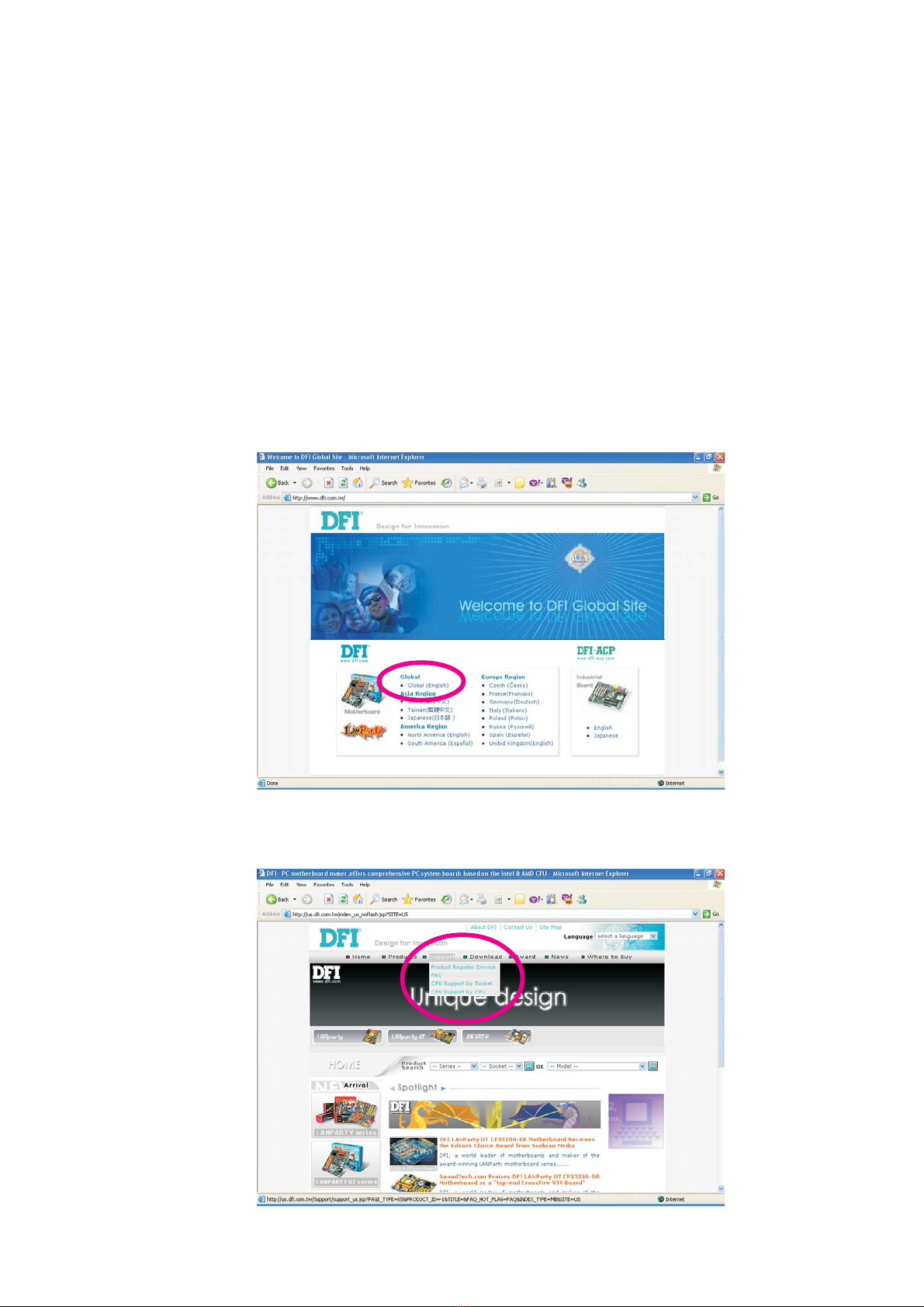
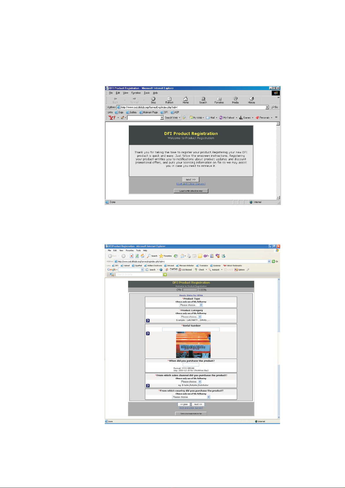
Registering the Product.......................................................................
Static Electricity Precaution................................................................
Safety Measures.....................................................................................
About the Package...............................................................................
Before Using the System Board.........................................................
Chapter 1 - Introduction....................................................................
Specifications...................................................................................................................................
Features..............................................................................................................................................
Français................................................................................................................................................
Deutsch...............................................................................................................................................
Español................................................................................................................................................
Ðóññêèé ÿçûê.........................................................................................................................
Japanese.............................................................................................................................................
Chapter 2 - Hardware Installation....................................................
System Board Layout ..........................................................................................................
System Memory..........................................................................................................................
CPU.......................................................................................................................................................
Jumper Settings............................................................................................................................
Rear Panel I/O Ports.............................................................................................................
Internal I/O Connectors.....................................................................................................
Chapter 3 - BIOS Setup......................................................................
Award BIOS Setup Utility.................................................................................................
RAID BIOS.....................................................................................................................................
Updating the BIOS..................................................................................................................
Chapter 4 - Supported Softwares.....................................................
Chapter 5 - Cool’n’Quiet Technology..............................................
Chapter 6 - RAID.................................................................................
Chapter 7 - SLI Technology.................................................................
Appendix A - System Error Message...............................................
Appendix B - Troubleshooting..........................................................
5
5
6
8
8
9
9
10
10
12
17
19
21
23
25
27
27
28
31
37
40
54
74
74
123
124
126
144
146
151
157
159

About this Manual
An electronic file of this manual is included in the CD. To view the
user’s manual, insert the CD into a CD-ROM drive. The autorun
screen (Mainboard Utility CD) will appear. Click the “TOOLS” icon
then click “Manual” on the main menu.
Warranty
1. Warranty does not cover damages or failures that arised from
misuse of the product, inability to use the product, unauthorized
replacement or alteration of components and product
specifications.
2. The warranty is void if the product has been subjected to
physical abuse, improper installation, modification, accidents or
unauthorized repair of the product.
3. Unless otherwise instructed in this user’s manual, the user may
not, under any circumstances, attempt to perform service,
adjustments or repairs on the product, whether in or out of
warranty. It must be returned to the purchase point, factory or
authorized service agency for all such work.
4. We will not be liable for any indirect, special, incidental or
consequencial damages to the product that has been modified
or altered.

Introduction
1
6
Registering the Product
We encourage you to register your DFI product online. DFI’s product
registration service entitles you to notifications about product
updates, special discounts and/or promotional offers; and puts your
licensing information on file so that we may efficiently assist you if in
any case needed. Please follow the steps below to access the
product registration page.
1. Run Internet Explorer then type www.dfi.com.tw in the Address bar.
On DFI’s homepage, click Global or the language of your choice.
2. Click the Support menu then select Product Register Service.

1
Introduction
7
3. The DFI Product Registration page will appear. Click Next to
continue.
4. Select or fill in the necessary information to complete the
registration.
5. Thank you for registering your DFI product.

Introduction
1
8
Static Electricity Precautions
It is quite easy to inadvertently damage your PC, system board,
components or devices even before installing them in your system
unit. Static electrical discharge can damage computer components
without causing any signs of physical damage. You must take extra
care in handling them to ensure against electrostatic build-up.
1. To prevent electrostatic build-up, leave the system board in its
anti-static bag until you are ready to install it.
2. Wear an antistatic wrist strap.
3. Do all preparation work on a static-free surface.
4. Hold the device only by its edges. Be careful not to touch any of
the components, contacts or connections.
5. Avoid touching the pins or contacts on all modules and
connectors. Hold modules or connectors by their ends.
Important:
Electrostatic discharge (ESD) can damage your processor, disk
drive and other components. Perform the upgrade instruction
procedures described at an ESD workstation only. If such a
station is not available, you can provide some ESD protection
by wearing an antistatic wrist strap and attaching it to a metal
part of the system chassis. If a wrist strap is unavailable,
establish and maintain contact with the system chassis
throughout any procedures requiring ESD protection.
Safety Measures
To avoid damage to the system:
• Use the correct AC input voltage range.....
To reduce the risk of electric shock:
• Unplug the power cord before removing the system chassis
cover for installation or servicing. After installation or servicing,
cover the system chassis before plugging the power cord.
Battery:
• Danger of explosion if battery incorrectly replaced.
• Replace only with the same or equivalent type recommend
by
the manufacturer.
• Dispose of used batteries according to the battery
manufacturer’s
instructions.

1
Introduction
9
About the Package
The system board package contains the following items. If any of
these items are missing or damaged, please contact your dealer or
sales representative for assistance.
;One system board
;One Karajan audio module
;One SLI bridge
;One IDE round cable
;One floppy round cable
;Four Serial ATA data cables
;Two Serial ATA power cables
;One I/O shield
;One RAID driver diskette
;One “Mainboard Utility” CD
;One user’s manual
;One Quick Installation Guide
The system board and accessories in the package may not come
similar to the information listed above.This may differ in accordance
to the sales region or models in which it was sold. For more
information about the standard package in your region, please
contact your dealer or sales representative.
Before Using the System Board
Before using the system board, prepare basic system components.
If you are installing the system board in a new system, you will need
at least the following internal components.
•A CPU
•Memory module
•Storage devices such as hard disk drive, CD-ROM, etc.
You will also need external system peripherals you intend to use
which will normally include at least a keyboard, a mouse and a video
display monitor.

Introduction
1
10
Chapter 1 - Introduction
Specifications
Processor
HyperTransport
Chipset
System Memory
Expansion Slots
BIOS
Power Management
Hardware Monitor
LAN
• AMD®AthlonTM 64 FX / AthlonTM 64 X2 / AthlonTM 64
• Socket AM2
• 2000MT/s HyperTransport interface
• NVIDIA nForce®590 SLI MCP
- Northbridge: NVIDIA®C51XE
- Southbridge: NVIDIA®MCP55PXE
• Four 240-pin DDR2 DIMM sockets
• Supports DDR2 533 and DDR2 667 DIMMs
• Supports dual channel (128-bit wide) memory interface
• Supports up to 4GB system memory
• Supports non-ECC x8 and x16 DIMMs
• Supports unbuffered DIMMs
• 2 PCI Express x16 slots
- In SLI or Single VGA mode, each slot operates at full speed
x16 lanes.
- Use identical SLI-ready PCI Express x16 graphics cards
• 1 PCI Express x1 slot
• 1 PCI Express x8 slot
• 3 PCI slots
• Award BIOS
• CMOS Reloaded
• CPU/DRAM overclocking
• CPU/DRAM/Chipset overvoltage
• 4Mbit flash memory
• ACPI and OS Directed Power Management
• ACPI STR (Suspend to RAM) function
• Wake-On-PS/2 Keyboard/Mouse
• Wake-On-LAN
• RTC timer to power-on the system
• AC power failure recovery
• Monitors CPU/system/chipset temperature
•Monitors 12V/5V/3.3V/Vcore/Vbat/5Vsb/Vdimm/Vchip
voltages
• Monitors the speed of the cooling fans
• CPU Overheat Protection function monitors CPU temperature
during system boot-up
• NVIDIA®MCP55PXE integrated with Gigabit MAC (Media Ac-
cess Control) technology
• Two Vitesse VSC8601 Gigabit Phy chips
• Fully compliant to IEEE 802.3 (10BASE-T), 802.3u (100BASE-
TX) and 802.3ab (1000BASE-T) standards

1
Introduction
11
Audio
IDE
Serial ATA with
RAID
IEEE 1394
Rear Panel I/O
Internal I/O
PCB
• Karajan audio module
- Realtek ALC885 8-channel High Definition Audio CODEC
- 6 audio jacks
- 1 CD-in connector
- 1 front audio connector
• DAC SNR/ADC SNR of 106dB/101dB
• Full-rate lossless content protection technology
• S/PDIF-in/out interface
• One IDE connector allows connecting up to two UltraDMA
133Mbps hard drives
• Six Serial ATA ports supported by NVIDIA®MCP55PXE
- SATA speed up to 3Gb/s
- RAID 0, RAID 1, RAID 0+1 and RAID 5
• Two Serial ATA ports supported by Silicon Image SiI3132
- SATA speed up to 3Gb/s
- RAID 0, RAID 1 and RAID 0+1
• VIA VT6307
• Supports two 100/200/400 Mb/sec ports
• 1 mini-DIN-6 PS/2 mouse port
• 1 mini-DIN-6 PS/2 keyboard port
• 2 S/PDIF RCA jacks (S/PDIF-in and S/PDIF-out)
• Karajan audio module (6 audio jacks)
• 1 IEEE 1394 port
• 2 RJ45 LAN ports
• 6 USB 2.0/1.1 ports
• 2 connectors for 4 additional external USB 2.0/1.1 ports
• 1 connector for 1 external IEEE 1394 port
• 1 connector for 1 external serial port
• 1 connector for the Karajan audio module
• 1 front audio connector for external line-out and mic-in jacks
(on the Karajan audio module)
• 1 CD-in internal audio connector (on the Karajan audio module)
• 1 S/PDIF connector for optical cable connection
• 1 IrDA connector
• 1 CIR connector
• 8 Serial ATA connectors
• 1 IDE connector
•1 90
ofloppy connector
• 1 24-pin ATX power connector
• 1 8-pin ATX 12V power connector
• 1 4-pin 5V/12V power connector (FDD type)
• 1 front panel connector
• 5 fan connectors
• 1 Debug LED
• EZ touch switches (power switch and reset switch)
• ATX form factor
• 24cm (9.45") x 30.5cm (12")

Introduction
1
12
Features
The system board supports the AMD
AthlonTM 64 X2 / Athlon 64 FX /
AthlonTM 64 / SempronTM processor
for Socket AM2. AMD AthlonTM 64
provides superior computing for many software applications by al-
lowing both 32-bit and 64-bit applications to run simultaneously on
the same platform. The operating system and software are able to
process more data and access a tremendous amount of memory
which improves the overall system performance.
2T timing which provides better system stability is supported in CG
or later revisions of the AMD AthlonTM 64 processor.You can select
the memory timing in the Genie BIOS Setting submenu (“DRAM
Configuration” section) of the BIOS.
The AMD Cool‘n’QuietTM technology allows
the system to detect the CPU’s tasks and
utilization status. When the CPU’s task slows down, the system effec-
tively lowers power consumption by lowering its CPU speed and
voltage, subsequently decreasing its noise level.
The NVIDIA®SLITM (Scalable Link Interface) technology
connects two SLI-ready PCI Express graphics cards in a
single and scalable system. The two identical graphics
cards, which are connected via the SLI bridge, will pro-
vide extreme performance allowing you to enjoy games with the
most visual effects and the most graphics demanding multimedia
utilities. Dual GPUs provide increased 3D graphics and and doubles
the graphics performance.
PCI Express is a high bandwidth I/O infrastructure
that possesses the ability to scale speeds by forming
multiple lanes. The system board currently supports
the physical layer of x1, x8 and x16 lane widths.
The x1 PCI Express lane supports transfer rate of 2.5 Gigabytes
(250MBbps) per second.The PCI Express architecture also provides
a high performance graphics infrastructure by enhancing the capability
of a x16 PCI Express lane to provide 4 Gigabytes per second
transfer rate.
Cool‘n’QuietTM

1
Introduction
13
CPU Overheat Protection has the capability of
monitoring the CPU’s temperature during sys-
tem boot up. Once the CPU’s temperature
exceeded the temperature limit pre-defined by the CPU, the system
will automatically shutdown.This preventive measure has been added
to protect the CPU from damage and insure a safe computing envi-
ronment.
DDR2 is a higher performance DDR technology whose
data transfer rate delivers bandwidth of 4.3 GB per
second and beyond.That is twice the speed of the con-
ventional DDR without increasing its power consump-
tion. DDR2 SDRAM modules work at 1.8V supply compared to
2.6V memory voltage for DDR modules. DDR2 also incorporates
new innovations such as the On-Die Termination (ODT) as well as
larger 4-bit pre-fetch against DDR which fetches 2 bits per clock
cycle.
CMOS Reloaded is a technology that allows storing
multiple user-defined BIOS settings by using the
BIOS utility to save, load and name the settings.This
is especially useful to overclockers who require sav-
ing a variety of overclocked settings and being able
to conveniently switch between these settings simultaneously.
The Karajan audio module at the rear I/O panel has 6
audio jacks that provide 8-channel audio output for ad-
vanced 7.1-channel super surround sound audio system.
It is also equipped with a CD-in and front audio connec-
tor.
CPU Overheat
Protection

Introduction
1
14
S/PDIF is a standard audio file transfer format that trans-
fers digital audio signals to a device without having to be
converted first to an analog format. This prevents the
quality of the audio signal from degrading whenever it is
converted to analog. S/PDIF is usually found on digital audio equip-
ment such as a DAT machine or audio processing device. The
S/PDIF connector on the system board sends surround sound and
3D audio signal outputs to amplifiers and speakers and to digital
recording devices like CD recorders.
Serial ATA is a storage interface that is compli-
ant with SATA 1.0 specification. NVIDIA®
MCP55PXE and Silicon Image SiI3132 both support speed of up
to 3Gb/s. Serial ATA improves hard drive performance faster than
the standard parallel ATA whose data transfer rate is 100MB/s.
The NVIDIA®MCP55PXE chip allows configuring RAID
on Serial ATA drives. It supports RAID 0, RAID 1, RAID
0+1 and RAID 5.
The Silicon Image SiI3132 chip allows configuring RAID
on another 2 Serial ATA ports. It supports RAID 0, RAID
1 and RAID 0+1.
The Gigabit MAC (Media Access Control) technology inte-
grated in the NVIDIA®MCP55PXE chip, together with
the dual Vitesse VSC8601 Gigabit Phy chips provide fully
functional Gigabit LAN ports.

1
Introduction
15
IEEE 1394 is fully compliant with the 1394 OHCI (Open
Host Controller Interface) 1.1 specification. It supports up
to 63 devices that can run simultaneously on a system.
1394 is a fast external bus standard that supports data
transfer rates of up to 400Mbps. In addition to its high speed, it
also supports isochronous data transfer which is ideal for video de-
vices that need to transfer high levels of data in real-time. 1394
supports both Plug-and-Play and hot plugging.
The system board is equipped with an IrDA connector
for wireless connectivity between your computer and
peripheral devices.The IRDA (Infrared Data Association) specification
supports data transfers of 115K baud at a distance of 1 meter.
The system board supports USB 2.0 and USB 1.1
ports. USB 1.1 supports 12Mb/second bandwidth
while USB 2.0 supports 480Mb/second bandwidth
providing a marked improvement in device transfer
speeds between your computer and a wide range of simultaneously
accessible external Plug and Play peripherals.
This feature allows the network to remotely
wake up a Soft Power Down (Soft-Off) PC.
It is supported via the onboard LAN port or via a PCI LAN card
that uses the PCI PME (Power Management Event) signal. However,
if your system is in the Suspend mode, you can power-on the system
only through an IRQ or DMA interrupt.
Important:
The 5VSB power source of your power supply must support
≥
720mA.
This function allows you to use the PS/2 key-
board or PS/2 mouse to power-on the sys-
tem.
Important:
The 5VSB power source of your power supply must support
≥
720mA.
Wake-On-LAN
IrDA
Wake-On-PS/2

Introduction
1
16
The RTC installed on the system board allows your
system to automatically power-on on the set date and
time.
The system board is designed to meet the ACPI (Ad-
vanced Configuration and Power Interface) specification.
ACPI has energy saving features that enables PCs to implement
Power Management and Plug-and-Play with operating systems that
support OS Direct Power Management. Currently, only Windows®®
®®
®
2000/XP supports the ACPI function. ACPI when enabled in the
Power Management Setup will allow you to use the Suspend to
RAM function.
With the Suspend to RAM function enabled, you can power-off the
system at once by pressing the power button or selecting “Standby”
when you shut down Windows®®
®®
®2000/XP without having to go
through the sometimes tiresome process of closing files, applications
and operating system. This is because the system is capable of
storing all programs and data files during the entire operating session
into RAM (Random Access Memory) when it powers-off. The
operating session will resume exactly where you left off the next time
you power-on the system.
Important:
The 5VSB power source of your power supply must support
≥
1A.
When power returns after an AC power fail-
ure, you may choose to either power-on the
system manually, let the system power-on au-
tomatically or return to the state where you left off before power
failure occurs.
rtc
str
power failure
recovery

1
Introduction
17
Français
Processeur
Chipset
Mémoire Système
Logements
d’Extension
BIOS
Gestion de
Puissance
Fonctions de
Moniteur de
Matériel
LAN
• AMD®AthlonTM 64 FX / AthlonTM 64 X2 / AthlonTM 64
• Socket AM2
• Interface HyperTransport 2000MT/s
• NVIDIA nForce®590 SLI MCP
- Pont nord: NVIDIA®C51XE
- Pont sud: NVIDIA®MCP55PXE
• 4 sockets DIMM DDR2 240-pin
• Supporte les modules DIMM DDR2 533 et DDR2 667
• Supporte l’interface de mémoire deux canaux (128-bit)
• Supporte jusqu’à 4GB de mémoire système
• Supporte exclusivement les modules DIMM non-ECC x8 et x16
• Supporte les DIMM non-tamponnés
• 2 slots PCI Express x16
- Mode SLI ou Mode VGA Seul: Chaque slot fonctionne à la
bande passante x16.
- Utiliser les cartes graphiques PCI Express x16 de SLI-prêtes
identiques
• 1 slot PCI Express x1
• 1 slot PCI Express x8
• 3 slots PCI
• Compatible avec Award BIOS
• CMOS Reloaded
• Overclocking de CPU/DRAM
• Contrôle du voltage de CPU/DRAM/Chipset
• Mémoire Flash 4Mbit
• ACPI et OS Directed Power Management
• ACPI STR (Suspend to RAM) fonction
• Réveil-Sur-PS/2 Clavier/Souris
• Eveil Sonnerie
• Minuterie RTC pour allumer le système
• Récupération après Défaillance d’Alimentation CA
• Gère l’alarme de température et de surchauffe de CPU/
système/chipset
• Gère l’alarme de voltage et d’échec de 12V/5V/3.3V/Vcore/
Vbat/5Vsb/Vdimm/Vchip
• Gère la vitesse de ventilateur du ventilateur
• Protection du CPU - supporte la mise hors circuit automatique
en cas de surchauffage du système
• NVIDIA®MCP55PXE avec la technologie integrée Gigabit MAC
(Media Access Control)
• 2 Vitesse VSC8601 Gigabit Phy
• Supporte IEEE 802.3 (10BASE-T), 802.3u (100BASE-TX) et
802.3ab (1000BASE-T)
Caractéristiques et Spécifications

Introduction
1
18
Audio
IDE
Serial ATA avec
RAID
IEEE 1394
Panneau Arrière I/O
Interne I/O
PCB
• Karajan carte audio
- Realtek ALC885 8-canaux Définition Élevée audio CODEC
- 6 prises audio
- 1 connecteur CD-in
- 1 connecteur audio de l’avant
• DAC SNR/ADC SNR de 106dB/101dB
• Technologie protection de contente lossless à toute vitesse
• Interface entrée/sortie S/PDIF
• Supporte des disques durs jusqu’à UltraDMA 133Mbps
• 6 ports de série ATA gérés avec la puce NVIDIA®MCP55PXE
- Vitesse SATA jusqu’à 3Gb/s
- RAID 0, RAID 1, RAID 0+1 et RAID 5
• 2 ports de série ATA gérés par Silicon Image Sil 3132
- Vitesse SATA jusqu’à 3Gb/s
- RAID 0, RAID 1 et RAID 0+1
• VIA VT6307
• Supporte 2 100/200/400 Mb/sec ports
• 1 port souris PS/2 et 1 port clavier PS/2
• 2 S/PDIF RCA prises (S/PDIF-in et S/PDIF-out)
• 1 carte Karajan (6 prises audio)
• 1 port IEEE 1394
• 2 ports RJ45 LAN
• 6 ports USB 2.0/1.1
•2 connecteurs pour 4 ports USB 2.0/1.1 supplémentaires
• 1 connecteur pour 1 IEEE 1394
• 1 connecteur pour 1 série
• 1 connecteur pour module audio Karajan
• 1 connecteur audio frontal pour les jacks de sortie externe et
d’entrée micro (sur le module audio Karajan)
•1 connecteur CD-in audio internes (sur le module audio
Karajan)
• 1 S/PDIF l’assemblage pour l’adjonction de câble optique
• 1 connecteur IR
• 1 connecteur CIR
•8 connecteurs Serial ATA
• 1 connecteur IDE
• 1 connecteur de 90o FDD
• 1 connecteur d’alimentation 24-pin ATX
• 1 connecteur d’alimentation 8-pin 12V ATX
• 1 prises d’alimentation 4-broches 5V/12V (type-FDD)
• 1 connecteur devant panneau
• 5 connecteurs de ventilateurs
• 1 indicateur diagnostiques
• EZ interrupteurs (bouton de power et reset)
• Facteur de forme de ATX
• 24cm (9.45") x 30.5cm (12")

1
Introduction
19
Deutsch
Prozessor
Chipset
Systemspeicher
Expansion Schlitz
BIOS
Energie
Management
Kleinteilmonitor
LAN
• AMD®AthlonTM 64 FX / AthlonTM 64 X2 / AthlonTM 64
• Socket AM2
• Interface HyperTransport 2000MT/s
• NVIDIA nForce®590 SLI MCP
- Nordbrücke: NVIDIA®C51XE
- Südbrücke: NVIDIA®MCP55PXE
• 4 Sockel 240-pin DDR2 DIMM
• Unterhält DDR2 533 und DDR2 667 DIMMs
• Unterhält 128-bit – Speiher mit den zwei Kanälen
• Unterhält bis zum 4GB-Systemspeicher
• Unterhält nur non-ECC x8 und x16 DIMMs
• Unterhält DIMMs ohne Dämpfer
• 2 PCI Express x16-Einbauplätzen
- SLI-Modus oder Single-VGA-Modus: - Die Bandbreite der
Steckplätze beträgt jeweils x16
- Benutzen Sie identische SLI-bereite PCI ausdrückliche Karten
der Graphiken x16
• 1 PCI Express x1-Einbauplätzen
• 1 PCI Express x8-Einbauplätzen
• 3 PCI-Einbauplätzen
• Kompatibilität mit Award BIOS
• CMOS Reloaded
• Die Frequenzerhöhung CPU/DRAM
• Spannungserhöhung CPU/DRAM/Chipset
• Flash-Speicher (4Mbit)
• ACPI und OS Directed Power Management
• ACPI STR (Suspend to RAM) funktion
• Wecken bei Betätigung der PS/2 Tastatur/Maus
• Wecken des Systems durch das Netzwerk
• RTC-Taktgeber zum Einschalten des Systems
• Wiederherstellung der Wechselstromversorgung nach einem Ausfall
• Überwachung der Temperatur des CPU/Systems/Chipset sowie
Warnsignal bei Überhitzung
• Überwachung der Spannungen des 12V/5V/3.3V/Vcore/Vbat/
5Vsb/Vdimm/Vchip
• Überwachung der Geschwindigkeit des Ventilators
• Prozessor-Shutz - Die Ausschaltung bei der Überhitzung – die
automatische Ausschaltung des Computers bei der Überhitzung
• NVIDIA®MCP55PXE integriert mit Gigabit MAC (Media Ac-
cess Control) Technologie
• 2 Vitesse VSC8601 Gigabit Phy
• Unterstützt IEEE 802.3 (10BASE-T), 802.3u (100BASE-TX) und
802.3ab (1000BASE-T)
Leistungsmerkmale und Technische Daten

Introduction
1
20
Audio
IDE
Serial ATA mit RAID
IEEE 1394
Porte an der
Rückwand
Internes I/O
PCB
• Karajan-platine
- Realtek ALC885 8-Kanal-Hohe-Definition-audio-CODEC
- 6 Audio-Anschlußbuchsen
- 1 interne Audioanschlüsse (CD-in)
- 1 Frontaudioanschluß
• DAC SNR/ADC SNR von 106dB/101dB
• Lossless zufriedene Schutzvollwegtechnologie
• S/PDIF-In/Aus-Schnittstelle
• Unterstützung der Festplatten bis zum UltraDMA 133Mbps
• 6 serielle Serial ATA-Ports, unterstützt von einem NVIDIA®
MCP55PXE
- SATA bis zu 3Gb/s schnell
- RAID 0, RAID 1, RAID 0+1 und RAID 5
• 2 serielle ATA-Ports, unterstützt von Silicon Image Sil 3132
- SATA bis zu 3Gb/s schnell
- RAID 0, RAID 1 und RAID 0+1
• VIA VT6307
• Unterstützt 2 100/200/400 Mb/sec porte
• 1 Mini-DIN-6-Anschluß für eine PS/2-Maus
• 1 Mini-DIN-6-Anschluß für eine PS/2-Tastatur
• 2 S/PDIF RCA-Anschlüsse (S/PDIF-in und S/PDIF-out)
• Karajan-platine (6 Audio-Anschlußbuchsen)
• 1 IEEE 1394-Anschlüsse
• 2 RJ45 LAN-Anschlüsse
• 6 USB 2.0/1.1-Anschlüsse
•2
Anschlußfassung für 4 zusätzliche externe USB 2.0/1.1-Anschlüsse
• 1 Anschluß für eine externe IEEE 1394 Schnittstelle
• 1 Anschluß für eine externe serieller DB-9-Anschluß
• 1 Anschluß für eine Karajan Audiomodul
• 1 Front-Audioanschluss für externe Mikrofon-Ein- und –
Ausgänge (im Karajan Audiomodul)
• 1 CD-in interne Audioanschlüsse (im Karajan Audiomodul)
• 1 S/PDIF Anschluß für die Verbindung des optischen Kabel
• 1 Anschluß für die IR-Schnittstelle
• 1 CIR-Schnittstelle
• 8 Serial ATA-Anschlüsse
• 1 IDE-Anschlüsse
•1 90
o Floppy-Anschlüsse
• 1 24-polige Anschlußstecker für das ATX-Netzgerät
• 1 8-polige 12V Anschlußstecker für das ATX-Netzgerät
• 1 4-polige 5V/12V Netzstecker (für FDD)
• 1 Vorderseite Füllung Anschlüsse
• 5-ventilator-Anschlüsse
• 1 diagnostischen Außenindikatoren
• EZ Umschaltern (der Knopf der Speisung und des Auslasses)
• ATX Formfaktor
• 24cm (9.45") x 30.5cm (12")
Table of contents
Other DFI Motherboard manuals