DFI CMS171 User manual

CMS171/CMS173
10th Gen Intel®CoreTM
User’s Manual
© August 15, 2023 DFI Inc.

2User's Manual | CMS171/CMS173
Copyright
This publication contains information that is protected by copyright. No part of it may be repro-
duced in any form or by any means or used to make any transformation/adaptation without the
prior written permission from the copyright holders.
This publication is provided for informational purposes only. The manufacturer makes no
representations or warranties with respect to the contents or use of this manual and specifi-
cally disclaims any express or implied warranties of merchantability or fitness for any particular
purpose. The user will assume the entire risk of the use or the results of the use of this docu-
ment. Further, the manufacturer reserves the right to revise this publication and make changes
to its contents at any time, without obligation to notify any person or entity of such revisions or
changes.
Changes after the publication’s first release will be based on the product’s revision. The website
will always provide the most updated information.
© 2023. All Rights Reserved.
Trademarks
Product names or trademarks appearing in this manual are for identification purpose only and
are the properties of the respective owners.
FCC and DOC Statement on Class B
This equipment has been tested and found to comply with the limits for a Class B digital
device, pursuant to Part 15 of the FCC rules. These limits are designed to provide reason-
able protection against harmful interference when the equipment is operated in a residential
installation. This equipment generates, uses and can radiate radio frequency energy and, if not
installed and used in accordance with the instruction manual, may cause harmful interference
to radio communications. However, there is no guarantee that interference will not occur in a
particular installation. If this equipment does cause harmful interference to radio or television
reception, which can be determined by turning the equipment off and on, the user is encour-
aged to try to correct the interference by one or more of the following measures:
• Reorient or relocate the receiving antenna.
• Increase the separation between the equipment and the receiver.
• Connect the equipment into an outlet on a circuit different from that to which the re-
ceiver is connected.
• Consult the dealer or an experienced radio TV technician for help.
Notice:
1. The changes or modifications not expressly approved by the party responsible for com-
pliance could void the user’s authority to operate the equipment.
2. Shielded interface cables must be used in order to comply with the emission limits.

3User's Manual | CMS171/CMS173
Table of Contents
Chapter 1 - Introduction................................................................................................................6
Specifications.........................................................................................................................6
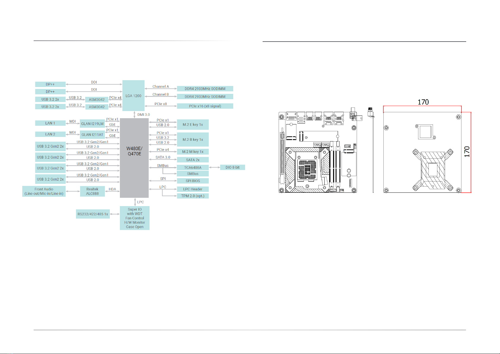
Block Diagram ........................................................................................................................8
Dimension...............................................................................................................................8
Chapter 2 - Hardware Installation................................................................................................9
Board Layout...........................................................................................................................9
Installing the heat sink.........................................................................................................10
Installing the Heat Sink.................................................................................................10
Jumper Settings...................................................................................................................11
Clear CMOS (JP1) .........................................................................................................11
Power Selection COM 1 (JP2)......................................................................................11
Pin Assignment....................................................................................................................12
System Fan (J9) ............................................................................................................12
SATA Power (CN1) ........................................................................................................12
CPU Fan (J10)................................................................................................................13
DIO Power (J12)............................................................................................................13
SATA0 (J1).....................................................................................................................14
SATA1 (J2).....................................................................................................................14
COM1 (J17)....................................................................................................................15
Front Audio (AUJ2)........................................................................................................15
Front Panel (J11)...........................................................................................................16
DIO (J13)........................................................................................................................16
LPC (J14).......................................................................................................................17
System Memory ...................................................................................................................18
Installing the SO-DIMM Module ...................................................................................18
Expansion Slots....................................................................................................................19
Installing the M.2 Module.............................................................................................19
Chapter 3 - BIOS Settings...........................................................................................................21
Overview ...............................................................................................................................21
Updating the BIOS................................................................................................................22
Notice: BIOS SPI ROM..........................................................................................................22
Main.......................................................................................................................................23
Advanced .............................................................................................................................23
RC ACPI Settings...........................................................................................................24
CPU Configuration.........................................................................................................24
Power & Performance...................................................................................................25
PCH-FW Configuration..................................................................................................25
Trusted Computing........................................................................................................26
NCT6126D Super IO Configuration..............................................................................26
NCT5525D Super IO Configuration ►Serial Port 1 Configuration......................27
NCT6126D HW Monitor ................................................................................................27
NCT6126D HW Monitor ►Smart FAN Function .................................................28
Serial Port Console Redirection ...................................................................................28
Serial Port Console Redirection ►Console Redirection Settings........................29
USB Configuration ........................................................................................................29
Network Stack Configuration........................................................................................30
CSM Configuration .......................................................................................................30
USB Power Control........................................................................................................31
Chipset..................................................................................................................................32
Graphics Configuration.................................................................................................32
PEG Port Configuration.................................................................................................33
PEG Port Configuration ►PEG Port Feature Configuration................................33
PCH-IO Configuration....................................................................................................34
Security .................................................................................................................................35
Secure Boot....................................................................................................................35
Boot.......................................................................................................................................36
Save & Exit............................................................................................................................36
Updating the BIOS................................................................................................................37
Notice: BIOS SPI ROM..........................................................................................................37

4User's Manual | CMS171/CMS173
About this Manual
This manual can be downloaded from the website.
The manual is subject to change and update without notice, and may be based on editions that
do not resemble your actual products. Please visit our website or contact our sales representa-
tives for the latest editions.
Warranty
1. Warranty does not cover damages or failures that occur from misuse of the product,
inability to use the product, unauthorized replacement or alteration of components and
product specifications.
2. The warranty is void if the product has been subjected to physical abuse, improper in-
stallation, modification, accidents or unauthorized repair of the product.
3. Unless otherwise instructed in this user’s manual, the user may not, under any circum-
stances, attempt to perform service, adjustments or repairs on the product, whether in
or out of warranty. It must be returned to the purchase point, factory or authorized ser-
vice agency for all such work.
4. We will not be liable for any indirect, special, incidental or consequential damages to
the product that has been modified or altered.
Static Electricity Precautions
It is quite easy to inadvertently damage your PC, system board, components or devices even
before installing them in your system unit. Static electrical discharge can damage computer
components without causing any signs of physical damage. You must take extra care in han-
dling them to ensure against electrostatic build-up.
1. To prevent electrostatic build-up, leave the system board in its anti-static bag until you
are ready to install it.
2. Wear an antistatic wrist strap.
3. Do all preparation work on a static-free surface.
4. Hold the device only by its edges. Be careful not to touch any of the components, con-
tacts or connections.
5. Avoid touching the pins or contacts on all modules and connectors. Hold modules or
connectors by their ends.
Safety Measures
• To avoid damage to the system, use the correct AC input voltage range.
• To reduce the risk of electric shock, unplug the power cord before removing the sys-
tem chassis cover for installation or servicing. After installation or servicing, cover the
system chassis before plugging the power cord.
Important:
Electrostatic discharge (ESD) can damage your processor, disk drive and other
components. Perform the upgrade instruction procedures described at an ESD
workstation only. If such a station is not available, you can provide some ESD pro-
tection by wearing an antistatic wrist strap and attaching it to a metal part of the
system chassis. If a wrist strap is unavailable, establish and maintain contact with
the system chassis throughout any procedures requiring ESD protection.

5User's Manual | CMS171/CMS173
About the Package
The package contains the following items. If any of these items are missing or damaged,
please contact your dealer or sales representative for assistance.
• 1 CMS171/CMS173 motherboard
• 1 Serial ATA data cable w/lock (Length: 500mm)
• 1 Serial ATA power Y cable (Length: 300mm, 1 x SATA POWER 15P*2 TO 4P HSG)
• 1 COM port cable (Length: 250mm, 1 x COM port)
The board and accessories in the package may not come similar to the information listed above.
This may differ in accordance with the sales region or models in which it was sold. For more
information about the standard package in your region, please contact your dealer or sales repre-
sentative.
Before Using the System Board
When installing the system board in a new system, you will need at least the following internal
components.
• Memory module
• Storage device such as a hard disk drive.
• Power supply
External system peripherals may also be required for navigation and display, including at least a
keyboard, a mouse and a video display monitor.

6
Chapter 1
INTRODUCTION
User's Manual | CMS171/CMS173
Chapter 1 - Introduction
X Specifications
SYSTEM Processor 10th Gen Intel®LGA 1200 Socket Processors, TDP support up to 125W
Intel®Xeon®W-1290E (10 Cores, 20M Cache, up to 4.8 GHz; 95W (ECC support on W480E SKU only)
Intel®Xeon®W-1290TE (10 Cores, 20M Cache, up to 4.5 GHz); 35W (ECC support on W480E SKU only)
Intel®Xeon®W-1270E (8 Cores, 16M Cache, up to 4.8 GHz); 80W (ECC support on W480E SKU only)
Intel®Xeon®W-1270TE (8 Cores, 16M Cache, up to 4.4 GHz); 35W (ECC support on W480E SKU only)
Intel®Xeon®W-1250E (6 Cores, 12M Cache, up to 4.7 GHz); 80W (ECC support on W480E SKU only)
Intel®Xeon®W-1250TE (6 Cores, 12M Cache, up to 3.8 GHz); 35W (ECC support on W480E SKU only)
Intel®Core™ i9-10900E (10 Cores, 20M Cache, up to 4.7 GHz); 65W
Intel®Core™ i9-10900TE (10 Cores, 20M Cache, up to 4.5 GHz); 35W
Intel®Core™ i7-10700E (8 Cores, 16M Cache, up to 4.5 GHz); 65W
Intel®Core™ i7-10700TE (8 Cores, 16M Cache, up to 4.4 GHz); 35W
Intel®Core™ i5-10500E (6 Cores, 12M Cache, up to 4.2 GHz); 65W
Intel®Core™ i5-10500TE (6 Cores, 12M Cache, up to 3.7 GHz); 35W
Intel®Core™ i3-10100E (4 Cores, 6M Cache, 3.8 GHz); 65W (ECC support on W480E SKU only)
Intel®Core™ i3-10100TE (4 Cores, 6M Cache, to 3.6 GHz); 35W (ECC support on W480E SKU only)
Intel®Pentium®G6400E (2 Cores, 4M Cache, 3.8 GHz); 58W (Not support on W480E SKU)
Intel®Celeron®G5900E (2 Cores, 2M Cache, 3.2 GHz); 58W (Not support on W480E SKU)
Intel®Celeron®G5900TE (2 Cores, 2M Cache, 3.0 GHz); 35W (Not support on W480E SKU)
Chipset Intel®W480E/Q470E Chipset
Memory Two 260-pin SODIMM up to 64GB
Dual Channel DDR4 2933MHz (ECC supported by W480E only)
BIOS AMI SPI 256Mbit
GRAPHICS Controller Intel®UHD Graphics 630 (only Pentium G5400/Celeron G4900 support 610 )
Feature OpenGL 4.5, DirectX 12, OpenCL 2.1
HW Decode: AVC/H.264, MPEG2, VC1/WMV9, JPEG/MJPEG, HEVC/H265, VP8, VP9
HW Encode: AVC/H.264, MPEG2, JPEG, HEVC/H265, VP8, VP9
Display 2 x DP++, resolution up to 4096 x 2106 @ 60Hz
Dual Displays 2 x DP++
EXPANSION Interface 1 x PCIe x16 (Gen 3) (x8 signal)
1 x M.2 2230 E key (PCIe/USB 2.0/Intel CNVi support) for WiFi6
1 x M.2 2280 M key (PCIe x4 Gen3 NVMe/SATA/Intel Optane Memory support) for SSD
1 x M.2 3042/3052 B key (PCIe/USB3.0) for 4G LTE/5G with SIM holder
AUDIO Audio Codec Realtek ALC888

7
Chapter 1
INTRODUCTION
User's Manual | CMS171/CMS173
ETHERNET Controller 1 x Intel®I219LM PHY with iAMT12 and vPro (10/100/1000Mbps) (Core i7/i5 supports iAMT)
1 x Intel®I211AT PCIe (10/100/1000Mbps)
REAR I/O Ethernet 2 x GbE (RJ-45)
Serial 1 x RS-232/422/485 (RS-232 w/ power) (DB-9)
USB 8 x USB 3.2 Gen2
4 x USB 3.2
Display 2 x DP++
INTERNAL I/O Serial 1 x RS-232/422/485 (RS-232 w/ power) (2.0mm pitch)
Audio 1 x Front Audio Header
SATA 2 x SATA 3.0 (up to 6Gb/s)
1 x SATA Power
RAID 0/1
DIO 1 x 8-bit DIO
LPC 1 x LPC
SMBus 1 x SMBus
WATCHDOG TIMER Output & Interval System Reset, Programmable via Software from 1 to 255 Seconds
SECURITY TPM Infineon TPM1.2/2.0 (optional)
POWER Type Single 12V +/-10% DC (CMS171)
Wide Range 15~36V (CMS173)
Connector 8-pin ATX 12V power
24-pin ATX power
Consumption TBD
RTC Battery CR2032 Coin Cell
OS SUPPORT Microsoft Windows 10 IoT Enterprise LTSC 2019 RS5
Linux Ubuntu 20.04
ENVIRONMENT Temperature Operating: -5 to 65°C
Storage: -40 to 85°C with RTC Battery; -40 to 85°C without RTC Battery
Humidity Operating: 5 to 90% RH
Storage: 5 to 90% RH
MTBF TBD
MECHANISM Dimensions Mini-ITX Form Factor : 170mm (6.7") x 170mm (6.7")
Height PCB: 1.6mm

8
Chapter 1
INTRODUCTION
User's Manual | CMS171/CMS173
X Block Diagram X Dimension

9
Chapter 2
HARDWARE INSTALLATION
User's Manual | CMS171/CMS173
Chapter 2 - Hardware Installation
X Board Layout
11
M.2 B Key
M.2 E Key
M.2 M Key
2
9 10
1
1
1
1
1
1
1
1
1
1
1
2
2
2
56
12
11
13
14
1
8
12
910
1
234567
9
8
10
11 12
13 14
15 16
19
20 21
25
26 27 28
23
22
24
17
18
1
21
28
2
22
3
23
4
24
5
25
6
26
7
27
8
9
10
11
12
14
15
16
17
18
19
20
13
Front Audio
DP++
USB3.2
USB3.2 Gen2
USB3.2 Gen2
▲LAN2
▼USB3.2 Gen2
▲LAN1
▼USB3.2 Gen2
DC-in
PCIe x16
SPI
SATA1
SATA0
SO-DIMM1
SO-DIMM2
SATA Power
CPU Fan
Buzzer
CLEAR CMOS
SIM Card Slot
Caseopen
COM1
8-bit DIO
Power Selection COM 1
DIO Power
Battery
LPC
System Fan
Front Panel

10
Chapter 2
HARDWARE INSTALLATION
User's Manual | CMS171/CMS173
X Installing the heat sink
11
M.2 B Key
M.2 E Key
M.2 M Key
2
9 10
1
1
1
1
1
1
1
1
1
1
1
2
2
2
56
12
11
13
14
1
8
12
910
Installing the Heat Sink
The CPU must be kept cool by using a heat sink, otherwise the CPU will overheat damaging
both the CPU and system board.
1. Before you install the fan / heat sink, you must apply a thermal paste onto the top of
the CPU. The thermal paste is usually supplied when you purchase the fan / heat sink
assembly. Do not spread the paste all over the surface. When you later place the heat
sink on top of the CPU, the compound will disperse evenly.
Some heat sinks come with a patch of preapplied thermal paste. Do not apply thermal
paste if the fan / heat sink already has a patch of thermal paste on its underside. Peel
the strip that covers the paste before you place the fan / heat sink on top of the CPU.
2. Place the heat sink on top of the CPU. The 4 spring screws around the heat sink, which
are used to secure the heat sink onto the system board, must match the 4 mounting
holes around the board.
3. Screw tight two of the spring screws at opposite corners into the mounting holes. And
then proceed with the other two spring screws.
Mounting holes
Mounting holes

11
Chapter 2
HARDWARE INSTALLATION
User's Manual | CMS171/CMS173
X Jumper Settings
Clear CMOS (JP1) Power Selection COM 1 (JP2)
11
M.2 B Key
M.2 E Key
M.2 M Key
2
9 10
1
1
1
1
1
1
1
1
1
1
1
2
2
2
56
12
11
13
14
1
8
12
910
11
M.2 B Key
M.2 E Key
M.2 M Key
2
9 10
1
1
1
1
1
1
1
1
1
1
1
2
2
2
56
12
11
13
14
1
8
12
910
1-2 On: Default
1
1
2-3 Off: Clear
12
56
66
55
22
11
1-3 /2-4 On:
RS232 Standard (Default) 3-5 /4-6 On:
RS232 with Power

12
Chapter 2
HARDWARE INSTALLATION
User's Manual | CMS171/CMS173
X Pin Assignment
System Fan (J9) SATA Power (CN1)
11
M.2 B Key
M.2 E Key
M.2 M Key
2
9 10
1
1
1
1
1
1
1
1
1
1
1
2
2
2
56
12
11
13
14
1
8
12
910
11
M.2 B Key
M.2 E Key
M.2 M Key
2
9 10
1
1
1
1
1
1
1
1
1
1
1
2
2
2
56
12
11
13
14
1
8
12
910
Pin Assignment
1GND
2PWM
3TACH
1
Pin Assignment
1+12V DC
2GND
3GND
4+5V DC

13
Chapter 2
HARDWARE INSTALLATION
User's Manual | CMS171/CMS173
CPU Fan (J10) DIO Power (J12)
11
M.2 B Key
M.2 E Key
M.2 M Key
2
9 10
1
1
1
1
1
1
1
1
1
1
1
2
2
2
56
12
11
13
14
1
8
12
910
11
M.2 B Key
M.2 E Key
M.2 M Key
2
9 10
1
1
1
1
1
1
1
1
1
1
1
2
2
2
56
12
11
13
14
1
8
12
910
1
1
Pin Assignment
1GND
212V
3RPM
4CTRL
Pin Assignment
112V
2GND
35VDU
45V

14
Chapter 2
HARDWARE INSTALLATION
User's Manual | CMS171/CMS173
SATA0 (J1) SATA1 (J2)
11
M.2 B Key
M.2 E Key
M.2 M Key
2
9 10
1
1
1
1
1
1
1
1
1
1
1
2
2
2
56
12
11
13
14
1
8
12
910
11
M.2 B Key
M.2 E Key
M.2 M Key
2
9 10
1
1
1
1
1
1
1
1
1
1
1
2
2
2
56
12
11
13
14
1
8
12
910
1
1
Pin Assignment
1GND
2TXP
3TXN
4GND
5RXN
6RXP
7GND
Pin Assignment
1GND
2TXP
3TXN
4GND
5RXN
6RXP
7GND

15
Chapter 2
HARDWARE INSTALLATION
User's Manual | CMS171/CMS173
COM1 (J17) Front Audio (AUJ2)
11
M.2 B Key
M.2 E Key
M.2 M Key
2
9 10
1
1
1
1
1
1
1
1
1
1
1
2
2
2
56
12
11
13
14
1
8
12
910
11
M.2 B Key
M.2 E Key
M.2 M Key
2
9 10
1
1
1
1
1
1
1
1
1
1
1
2
2
2
56
12
11
13
14
1
8
12
910
12
910
Pin Assignment Pin Assignment
1MDCD- 2MSIN-
3MSO- 4MDTR-
5GND 6MDSR-
7MRTS- 8MCTS-
9MRI- 10 ----
2
0
1
1
9
Pin Assignment Pin Assignment
1MIC2_L 2GND
3MIC2_R 4-ACZ_DET
5LINE2_R 6FSENSE1
7FAUDIO_JD 8NC
9LINE2_L 10 FSENSE2

16
Chapter 2
HARDWARE INSTALLATION
User's Manual | CMS171/CMS173
Front Panel (J11) DIO (J13)
11
M.2 B Key
M.2 E Key
M.2 M Key
2
9 10
1
1
1
1
1
1
1
1
1
1
1
2
2
2
56
12
11
13
14
1
8
12
910
11
M.2 B Key
M.2 E Key
M.2 M Key
2
9 10
1
1
1
1
1
1
1
1
1
1
1
2
2
2
56
12
11
13
14
1
8
12
910
1
2
12
11
Pin Assignment Pin Assignment
1NC 2V_SUS_LED
33V3 4V_SUS_LED
5HDD_LED 6SUS_LED
7GND 8GND
9SYS_RST- 10 PWR_BTN-
11 NC 12 ---
1
8
Pin Assignment
1DIO0
2DIO1
3DIO2
4DIO3
5DIO4
6DIO5
7DIO6
8DIO7

17
Chapter 2
HARDWARE INSTALLATION
User's Manual | CMS171/CMS173
LPC (J14)
11
M.2 B Key
M.2 E Key
M.2 M Key
2
9 10
1
1
1
1
1
1
1
1
1
1
1
2
2
2
56
12
11
13
14
1
8
12
910
1
2
13
14
Pin Assignment Pin Assignment
1CLK 2LAD1
3RST# 4LAD0
5FRAME# 6VCC3
7LAD3 8GND1
9LAD2 10 ---
11 SERIRQ 12 GND2
13 5VSB 14 5V

18
Chapter 2
HARDWARE INSTALLATION
User's Manual | CMS171/CMS173
X System Memory
11
M.2 B Key
M.2 E Key
M.2 M Key
2
9 10
1
1
1
1
1
1
1
1
1
1
1
2
2
2
56
12
11
13
14
1
8
12
910
1 2
1
2
SO-DIMM1
SO-DIMM2
Before installing the memory module, please make sure that the following safety cautions are
well-attended.
1. Make sure the PC and all other peripheral devices connected to it has been powered
down.
2. Disconnect all power cords and cables.
3. Locate the SO-DIMM socket on the system board
4. Make sure the notch on memory card is aligned to the key on the socket.
Installing the SO-DIMM Module
The system board supports the following memory interface.
Single Channel (SC)
Data will be accessed in chunks of 64 bits from the memory channels. DIMMs are on the same
channel. DIMMs in a channel can be identical or completely different. However, we highly rec-
ommend using identical DIMMs. Not all slots need to be populated.
Dual Channel (DC)
Data will be accessed in chunks of 128 bits from the memory channels. Dual channel provides
better system performance because it doubles the data transfer rate.
Socket Side View
Socket Top View
Memory Module
Notch
Key
Eject TabEject Tab

19
Chapter 2
HARDWARE INSTALLATION
User's Manual | CMS171/CMS173
X Expansion Slots
11
M.2 B Key
M.2 E Key
M.2 M Key
2
9 10
1
1
1
1
1
1
1
1
1
1
1
2
2
2
56
12
11
13
14
1
8
12
910
1
2
3
1
2
3
M.2 E-Key
M.2 M-Key
M.2 B-Key
Installing the M.2 Module
Before installing the M.2 module into the M.2 socket, please make sure that the following
safety cautions are well-attended.
1. Make sure the PC and all other peripheral devices connected to it has been powered
down.
2. Disconnect all power cords and cables.
3. Locate the M.2 socket on the system board
4. Make sure the notch on card is aligned to the key on the socket.
5. Make sure the standoff screw is removed from the standoff.
M.2 Module M.2 Socket
Key
Stand-off
Notch

20
Chapter 2
HARDWARE INSTALLATION
User's Manual | CMS171/CMS173
Please follow the steps below to install the card into the socket.
Step 2:
Press the end of the card far
from the socket down until
against the stand-off.
Step 3:
Screw tight the card onto the
stand-off with a screw driver
and a stand-off screw until
the gap between the card and
the stand-off closes up. The
card should be lying parallel to
the board when it’s correctly
mounted.
Step 1:
Insert the card into the socket
at an angle while making sure
the notch and key are perfectly
aligned.
M.2 Module M.2 Socket
Key
Stand-off
Notch
This manual suits for next models
1
Table of contents
Other DFI Motherboard manuals