DFI RNO171 User manual

Mini-ITX Industrial Motherboard
User’s Manual
RNO171

2User's Manual | RNO171
Copyright
This publication contains information that is protected by copyright. No part of it may be repro-
duced in any form or by any means or used to make any transformation/adaptation without the
prior written permission from the copyright holders.
This publication is provided for informational purposes only. The manufacturer makes no
representations or warranties with respect to the contents or use of this manual and specifi-
cally disclaims any express or implied warranties of merchantability or fitness for any particular
purpose. The user will assume the entire risk of the use or the results of the use of this docu-
ment. Further, the manufacturer reserves the right to revise this publication and make changes
to its contents at any time, without obligation to notify any person or entity of such revisions or
changes.
Changes after the publication’s first release will be based on the product’s revision. The website
will always provide the most updated information.
© 2022. All Rights Reserved.
Trademarks
Product names or trademarks appearing in this manual are for identification purpose only and
are the properties of the respective owners.
FCC and DOC Statement on Class B
This equipment has been tested and found to comply with the limits for a Class B digital
device, pursuant to Part 15 of the FCC rules. These limits are designed to provide reason-
able protection against harmful interference when the equipment is operated in a residential
installation. This equipment generates, uses and can radiate radio frequency energy and, if not
installed and used in accordance with the instruction manual, may cause harmful interference
to radio communications. However, there is no guarantee that interference will not occur in a
particular installation. If this equipment does cause harmful interference to radio or television
reception, which can be determined by turning the equipment off and on, the user is encour-
aged to try to correct the interference by one or more of the following measures:
• Reorient or relocate the receiving antenna.
• Increase the separation between the equipment and the receiver.
• Connect the equipment into an outlet on a circuit different from that to which the re-
ceiver is connected.
• Consult the dealer or an experienced radio TV technician for help.
Notice:
1. The changes or modifications not expressly approved by the party responsible for com-
pliance could void the user’s authority to operate the equipment.
2. Shielded interface cables must be used in order to comply with the emission limits.

3User's Manual | RNO171
Table of Contents
Chapter 1 - Introduction................................................................................................................6
Specifications ......................................................................................................................... 6
Features .................................................................................................................................. 8
DDR4................................................................................................................................. 8
Chapter 2 - Hardware Installation................................................................................................9
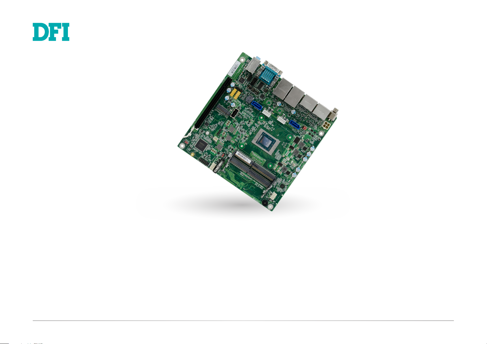
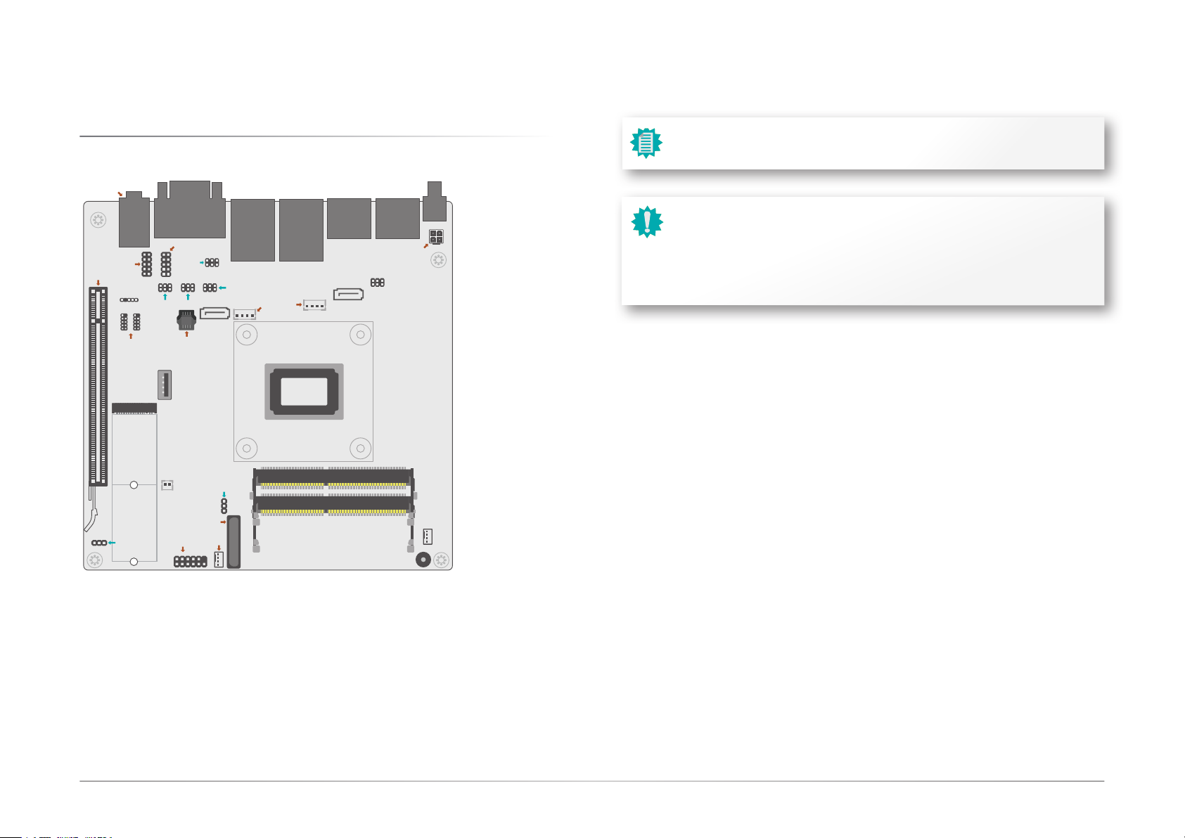
Board Layout........................................................................................................................... 9
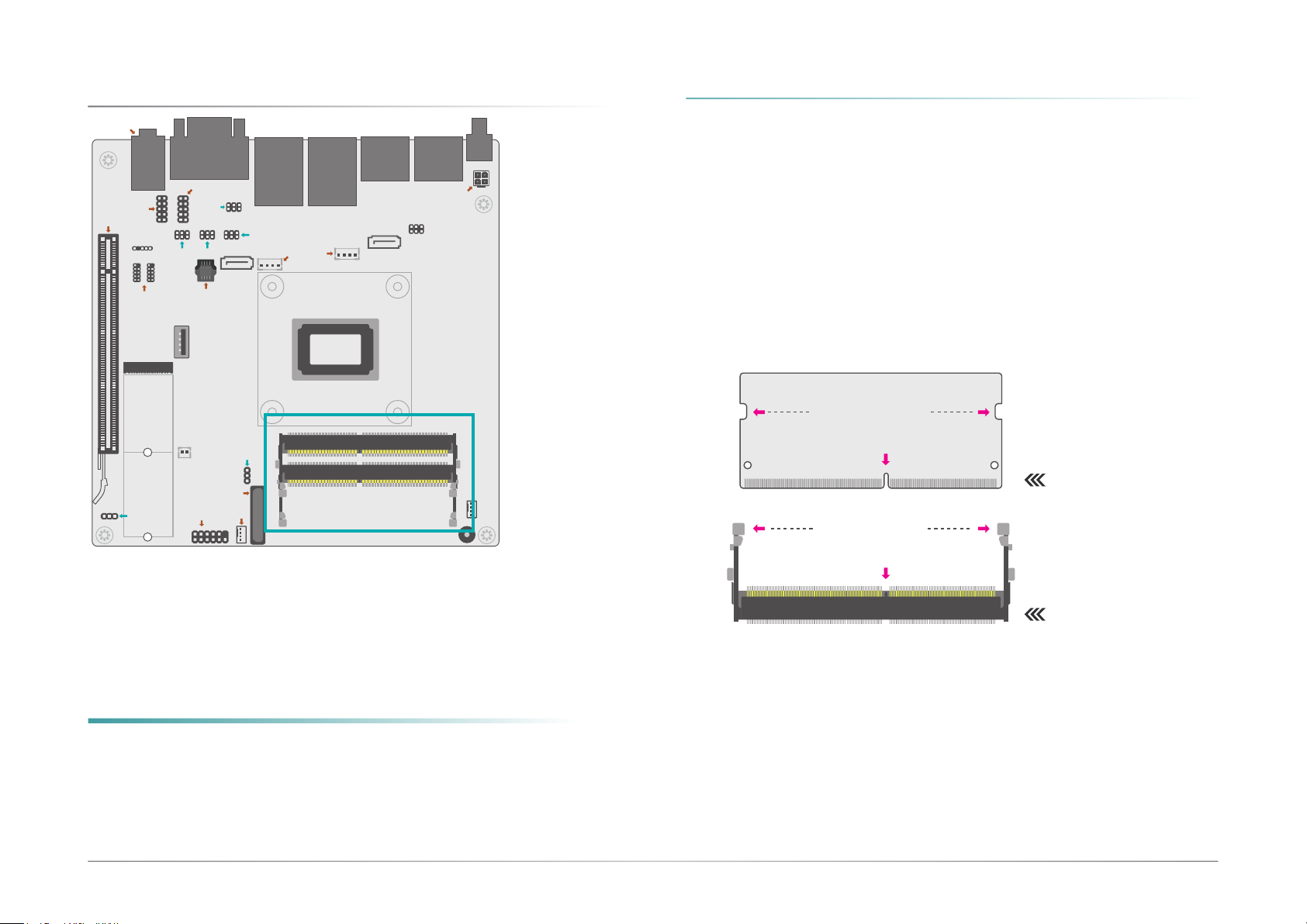
System Memory ...................................................................................................................10
Installing the SO-DIMM Module ...................................................................................10
Jumper Settings ...................................................................................................................12
SATA Power Selection (JP5) ........................................................................................12
Clear CMOS (JP6) .........................................................................................................13
Power Selection COM2 (TSJP1) ..................................................................................14
Selection for COM2 (TSJP2) ........................................................................................15
Selection for COM2 (TSJP3/TSJP4)............................................................................16
AT/ATX Mode (JP7) ......................................................................................................17
Rear I/O Ports.......................................................................................................................18
Graphics Display............................................................................................................18
USB Ports .......................................................................................................................19
RJ45 LAN Ports .............................................................................................................19
COM Ports......................................................................................................................20
Audio Ports ....................................................................................................................20
DC 12V............................................................................................................................21
Internal I/O Connectors .......................................................................................................22
12V DC-In .......................................................................................................................22
SATA (Serial ATA) and SATA Power.............................................................................22
COM (Serial) Port ..........................................................................................................23
Front Audio.....................................................................................................................23
S/PDIF.............................................................................................................................24
USB Ports .......................................................................................................................24
System Intrusion............................................................................................................25
Front Panel.....................................................................................................................26
CPU FAN.........................................................................................................................26
SYS FAN .........................................................................................................................27
LPC .................................................................................................................................27
Expansion Slots .............................................................................................................28
Installing the M.2 Module .............................................................................................29
Chapter 3 - BIOS Settings...........................................................................................................30
Overview ...............................................................................................................................30
Main.......................................................................................................................................31
Advanced .............................................................................................................................31
Trusted Computing........................................................................................................32
Chipset Configuration ...................................................................................................32
ACPI Configuration........................................................................................................33
NCT6216D Super IO Configuration ..............................................................................33
NCT6216D HW Monitor ................................................................................................34
Serial Port Console Redirection ...................................................................................35
CPU Configuration.........................................................................................................36
SATA Configuration .......................................................................................................37
USB Configuration .........................................................................................................38
Network Stack Configuration........................................................................................38
USB Power Control........................................................................................................39
Security .................................................................................................................................40
Secure Boot....................................................................................................................40
Boot .......................................................................................................................................42
Save & Exit ............................................................................................................................42
Updating the BIOS................................................................................................................43
Notice: BIOS SPI ROM..........................................................................................................43

4User's Manual | RNO171
About this Manual
This manual can be downloaded from the website. The manual is subject to change and up-
date without notice, and may be based on editions that do not resemble your actual products.
Please visit our website or contact our sales representatives for the latest editions.
Warranty
1. Warranty does not cover damages or failures that arised from misuse of the product,
inability to use the product, unauthorized replacement or alteration of components and
product specifications.
2. The warranty is void if the product has been subjected to physical abuse, improper in-
stallation, modification, accidents or unauthorized repair of the product.
3. Unless otherwise instructed in this user’s manual, the user may not, under any circum-
stances, attempt to perform service, adjustments or repairs on the product, whether in
or out of warranty. It must be returned to the purchase point, factory or authorized ser-
vice agency for all such work.
4. We will not be liable for any indirect, special, incidental or consequencial damages to
the product that has been modified or altered.
Static Electricity Precautions
It is quite easy to inadvertently damage your PC, system board, components or devices even
before installing them in your system unit. Static electrical discharge can damage computer
components without causing any signs of physical damage. You must take extra care in han-
dling them to ensure against electrostatic build-up.
1. To prevent electrostatic build-up, leave the system board in its anti-static bag until you
are ready to install it.
2. Wear an antistatic wrist strap.
3. Do all preparation work on a static-free surface.
4. Hold the device only by its edges. Be careful not to touch any of the components, con-
tacts or connections.
5. Avoid touching the pins or contacts on all modules and connectors. Hold modules or
connectors by their ends.
Safety Measures
• To avoid damage to the system, use the correct AC input voltage range.
• To reduce the risk of electric shock, unplug the power cord before removing the sys-
tem chassis cover for installation or servicing. After installation or servicing, cover the
system chassis before plugging the power cord.
Important:
Electrostatic discharge (ESD) can damage your processor, disk drive and other
components. Perform the upgrade instruction procedures described at an ESD
workstation only. If such a station is not available, you can provide some ESD pro-
tection by wearing an antistatic wrist strap and attaching it to a metal part of the
system chassis. If a wrist strap is unavailable, establish and maintain contact with
the system chassis throughout any procedures requiring ESD protection.

5User's Manual | RNO171
About the Package
The package contains the following items. If any of these items are missing or damaged,
please contact your dealer or sales representative for assistance.
• 1 RNO171 motherboard
• 1 I/O shield A49-GH1710-000G
• 1 Cooler
The board and accessories in the package may not come similar to the information listed
above. This may differ in accordance with the sales region or models in which it was sold. For
more information about the standard package in your region, please contact your dealer or
sales representative.
Optional Items
Item Name Part Number Description
SATA signal and power
cable
A81-002013-000G
USB port cable 332-253010-026G Length: 200mm
COM port cable A81-015041-018G Length: 300mm
Cooler A71-108114-010G
A71-108113-000G
for 15W, height: 35mm
for 45W, height: 47mm
The board and accessories in the package may not come similar to the information listed
above. This may differ in accordance with the sales region or models in which it was sold. For
more information about the standard package in your region, please contact your dealer or
sales representative.
Before Using the System Board
When installing the system board in a new system, you will need at least the following internal
components.
• Memory module
• Storage device such as hard disk drive .
• Power adaptor
External system peripherals may also be required for navigation and display, including at least
a keyboard, a mouse and a video display monitor.

6
Chapter 1
INTRODUCTION
User's Manual | RNO171
Chapter 1 - Introduction
X Specifications
System Processor AMD® Ryzen™ V2000 Series Processors
AMD® Ryzen™ V2748, 8C/16T, 4MB Cache, 7 CU, 2.9GHz (4.25GHz),45W
AMD® Ryzen™ V2546, 6C/12T, 3MB Cache, 6 CU, 3.0GHz (3.95GHz),45W
AMD® Ryzen™ V2718, 8C/16T, 4MB Cache, 7 CU, 1.7GHz (4.15GHz),15W
AMD® Ryzen™ V2516, 6C/12T, 3MB Cache, 6 CU, 2.1GHz (3.95GHz),15W
Memory Two 260-pin SODIMM up to 64GB
Dual channel DDR4 up to 3200MHz (ECC/ non ECC support)
BIOS AMI BIOS
Graphics Controller AMD® Radeon Graphics
Feature OpenGL 4.6, DirectX 12, OpenCL 2.1
HW Decode: AVC/H.264, MPEG2, VC1/WMV9, JPEG/MJPEG, HEVC/H265, VP8, VP9
HW Encode: MPEG2, AVC/H264, JPEG, HEVC/H265, VP8, VP9
Display 4 x DP++
DP++: resolution up to 4096x2160 @ 60Hz
Expansion Interface 1 x PCIe x16 (x8 Gen3)
1 x M.2 2242/2280 M Key (SATA 3.0/ PCIe x4)
Audio Audio Codec Realtek ALC888S-VD2-GR
Ethernet Controller 2 x Realtek RTL8119-CG (10/100/1000Mbps)
Rear I/O Ethernet 2 x GbE (RJ-45)
Serial 1 x RS-232/422/485 (DB-9)
1 x RS-232 (DB-9)
USB 2 x USB 3.1 Gen1
2 x USB 2.0
Display 4 x DP++
Audio 1 x Mic-in
1 x Line-in
1 x Line-out
Internal I/O Serial 4 x RS-232 (2.0mm pitch) (TX/RX signal only)
USB 4 x USB 2.0 (2.54mm pitch) (One signal is shared with the USB 2.0 Vertical Type A)
1 x USB 2.0 Vertical Type A
Audio 1 x S/PDIF
1 x Audio (Mic-in/Line-out)
SATA 2 x SATA 3.0 (up to 6GB/s) (with 7-pin VCC support)
2 x SATA Power
Watchdog Timer Output & Interval System Reset, Programmable via Software from 1 to 255 Seconds
Security TPM TPM2.0 (opt.)

7
Chapter 1
INTRODUCTION
User's Manual | RNO171
Power Type Single 12V +/-5% DC
Connector Straight Type Connector (4-pin)
DC-in Jack (available upon request)
Right Angle Connector (4-pin) (available upon request)
Consumption TBD
RTC Battery CR2032 Coin Cell
OS Support Microsoft Windows 10
Linux Linux
Environment Temperature Operating: -5 to 65°C
Storage: -40 to 85°C
Humidity Operating: 10 to 90% RH
Storage: 10 to 90% RH
MTBF TBD
Mechanical Dimension Mini-ITX Form Factor
170mm (6.7") x 170mm (6.7")

8
Chapter 1
INTRODUCTION
User's Manual | RNO171
X Features
Watchdog Timer
The Watchdog Timer function allows your application to regularly “clear” the system at the set
time interval. If the system hangs or fails to function, it will reset at the set time interval so that
your system will continue to operate.
DDR4
DDR4 delivers increased system bandwidth and improves performance. The advantages of
DDR4 provide an extended battery life and improve the performance at a lower power than
DDR3/DDR2.
Serial ATA
Serial ATA is a storage interface that is compliant with SATA 1.0a specification. With speed of
up to 6Gb/s (SATA 3.0), it improves hard drive performance faster than the standard parallel
ATA whose data transfer rate is 100MB/s.
Gigabit LAN
The Realtek RTL8119-CG Gigabit Ethernet Controllers support data transmission at 1Gbps.
Audio
The Realtek ALC888S-VD2-GR audio codec provides 7.1 channel High Definition audio output.
Wake-On-LAN
This feature allows the network to remotely wake up a Soft Power Down (Soft-Off) PC. It is
supported via the onboard LAN port or via a PCI LAN card that uses the PCI PME (Power Man-
agement Event) signal. However, if your system is in the Suspend mode, you can power-on the
system only through an IRQ or DMA interrupt.
Wake-On-USB
This function allows you to use a USB keyboard or USB mouse to wake up a system from the
S3 (STR - Suspend To RAM) state.
ACPI STR
The system board is designed to meet the ACPI (Advanced Configuration and Power Interface)
specification. ACPI has energy saving features that enables PCs to implement Power Manage-
ment and Plug-and-Play with operating systems that support OS Direct Power Management.
ACPI when enabled in the Power Management Setup will allow you to use the Suspend to RAM
function.
With the Suspend to RAM function enabled, you can power-off the system at once by pressing
the power button or selecting “Standby” when you shut down Windows®without having to go
through the sometimes tiresome process of closing files, applications and operating system.
This is because the system is capable of storing all programs and data files during the entire
operating session into RAM (Random Access Memory) when it powers-off. The operating ses-
sion will resume exactly where you left off the next time you power-on the system.
Power Failure Recovery
When power returns after an AC power failure, you may choose to either power-on the system
manually or let the system power-on automatically.
RTC Timer
The Real Time Clock (RTC) installed on the system board allows your system to automatically
power-on on the set date and time.

9
Chapter 2
HARDWARE INSTALLATION
User's Manual | RNO171
Chapter 2 - Hardware Installation
Important:
Electrostatic discharge (ESD) can damage your board, processor, disk drives,
add-in boards, and other components. Perform installation procedures at an ESD
workstation only. If such a station is not available, you can provide some ESD
protection by wearing an antistatic wrist strap and attaching it to a metal part of
the system chassis. If a wrist strap is unavailable, establish and maintain contact
with the system chassis throughout any procedures requiring ESD protection.
Note:
Specifications of these components are model-specific. Please refer to the specifi-
cations for detail.
X Board Layout
S/PDIF
1 5
Front
Audio
COM 3~6
(top to bottom)
JP5
PCIE1
12
9
10 1 2
1 4
1 4
9 10
LAN1
USB 1/2
(USB 3.1 Gen 1)
LAN2
USB 3/4
(USB 2.0)
USB 9
(USB2.0)
USB 7/8/5/6
(USB2.0)
(left to right)
12
9
12
9
Ryzen
V2000 Series Processor
AMD
TM
1
2
5
6
TSJP1
1
2
5
6
TSJP2
1
2
5
6
TSJP4
1
2
5
6
TSJP3
SATA1
(SATA3.0)
SATA POWER
SATA0
(SATA3.0)
1
2
5
6
1
4
Line In
Line Out
Mic In
12V ATX
power
DP 3/2 DP 1/0
COM 2/1
12V DC-IN
SYS FAN
1
CPU FAN
4
1
JP7
J8
DDR4_2 SODIMM (Top)
DDR4_1 SODIMM (Bottom)
Buzzer
Battery
Front Panel
1
12
2
111
3
12
M.2 M Key
JP6
1
3
SPI Flash BIOS

10
Chapter 2
HARDWARE INSTALLATION
User's Manual | RNO171
• 260-pin SO-DIMM up to 64GB
• DDR4 3200MHz
X System Memory
Features
The system board supports one dual channel DDR4 SO-DIMM memory module.
Single Channel (SC)
Data will be accessed in chunks of 64 bits from the memory channels.
Dual Channel (DC)
Data will be accessed in chunks of 128 bits from the memory channels. Dual channel provides
better system performance because it doubles the data transfer rate.
Installing the SO-DIMM Module
Before installing the memory module, please make sure that the following safety cautions are
well-attended.
1. Make sure the PC and all other peripheral devices connected to it has been powered
down.
2. Disconnect all power cords and cables.
3. Locate the SO-DIMM socket on the system board
4. Make sure the notch on memory card is aligned to the key on the socket.
X System Memory
Notch
Retention Notch
Key
Socket Top View
DDR4 SO-DIMM
Retention Clip
45°
Step 1
Step 2
Step 3
S/PDIF
1 5
Front
Audio
COM 3~6
(top to bottom)
JP5
PCIE1
12
9
10 1 2
1 4
1 4
9 10
LAN1
USB 1/2
(USB 3.1 Gen 1)
LAN2
USB 3/4
(USB 2.0)
USB 9
(USB2.0)
USB 7/8/5/6
(USB2.0)
(left to right)
12
9
12
9
Ryzen
V2000 Series Processor
AMD
TM
1
2
5
6
TSJP1
1
2
5
6
TSJP2
1
2
5
6
TSJP4
1
2
5
6
TSJP3
SATA1
(SATA3.0)
SATA POWER
SATA0
(SATA3.0)
1
2
5
6
1
4
Line In
Line Out
Mic In
12V ATX
power
DP 3/2 DP 1/0
COM 2/1
12V DC-IN
SYS FAN
1
CPU FAN
4
1
JP7
J8
DDR4_2 SODIMM (Top)
DDR4_1 SODIMM (Bottom)
Buzzer
Battery
Front Panel
1
12
2
111
3
12
M.2 M Key
JP6
1
3
SPI Flash BIOS

11
Chapter 2
HARDWARE INSTALLATION
User's Manual | RNO171
System Memory
Installing the SO-DIMM Module
Please follow the steps below to install the memory card into the socket.
Step 1:
Insert the memory card into the
slot while making sure 1) the
notch and the key are aligned,
and 2) the non-connector end
rises approximately 45 degrees
horizontally. Press the card firmly
into the socket while applying and
maintaining even pressure on both
ends.
Step 2:
Press the end of the card far from
the socket down while making
sure the retention notch and the
clip align as indicated by the dot-
ted line in the illustration. If the
retention notch and the clip do not
align, please remove the card and
re-insert it. Press the card all the
way down.
Step 3:
The clips snap automatically and
abruptly to the retention notches
of the card sounding a distinctive
click, and lock the card in place.
Inspect that the clip sits in the
notch. If not, please pull the clips
outward, release and remove the
card, and mount it again.
Notch
Retention Notch
Key
Socket Top View
DDR3 SO-DIMM
Retention Clip
45°
Step 1
Step 2
Step 3

12
Chapter 2
HARDWARE INSTALLATION
User's Manual | RNO171
X Jumper Settings
SATA Power Selection (JP5)
This switch is used to determine the SATA power output.
SATA Power Selection JP5
Standard SATA 1-3 On / 2-4 On
SATA+Power 3-5 On / 4-6 On
S/PDIF
1 5
Front
Audio
COM 3~6
(top to bottom)
JP5
PCIE1
12
9
10 1 2
1 4
1 4
9 10
LAN1
USB 1/2
(USB 3.1 Gen 1)
LAN2
USB 3/4
(USB 2.0)
USB 9
(USB2.0)
USB 7/8/5/6
(USB2.0)
(left to right)
12
9
12
9
Ryzen
V2000 Series Processor
AMD
TM
1
2
5
6
TSJP1
1
2
5
6
TSJP2
1
2
5
6
TSJP4
1
2
5
6
TSJP3
SATA1
(SATA3.0)
SATA POWER
SATA0
(SATA3.0)
1
2
5
6
1
4
Line In
Line Out
Mic In
12V ATX
power
DP 3/2 DP 1/0
COM 2/1
12V DC-IN
SYS FAN
1
CPU FAN
4
1
JP7
J8
DDR4_2 SODIMM (Top)
DDR4_1 SODIMM (Bottom)
Buzzer
Battery
Front Panel
1
12
2
111
3
12
M.2 M Key
JP6
1
3
SPI Flash BIOS

13
Chapter 2
HARDWARE INSTALLATION
User's Manual | RNO171
Jumper Settings
Clear CMOS (JP6)
Clear CMOS JP6
Normal (default) 1-2 On
Clear CMOS Data 2-3 On
If any anomaly of the followings is encountered —
• a) CMOS data is corrupted;
• b) you forgot the supervisor or user password;
• c) failure to start the system due to BIOS mis-configuration
— it is suggested that the system be reconfigured with default values stored in the ROM BIOS.
To load the default values stored in the ROM BIOS, please follow the steps below.
• 1. Power-off the system and unplug the power cord.
• 2. Put a jumper cap on pin 2 and pin 3. Wait for a few seconds and set it back to its
default setting, i.e. jumper cap on pin 1 and pin 2.
• 3. Plug the power cord and power-on the system.
S/PDIF
1 5
Front
Audio
COM 3~6
(top to bottom)
JP5
PCIE1
12
9
10 1 2
1 4
1 4
9 10
LAN1
USB 1/2
(USB 3.1 Gen 1)
LAN2
USB 3/4
(USB 2.0)
USB 9
(USB2.0)
USB 7/8/5/6
(USB2.0)
(left to right)
12
9
12
9
Ryzen
V2000 Series Processor
AMD
TM
1
2
5
6
TSJP1
1
2
5
6
TSJP2
1
2
5
6
TSJP4
1
2
5
6
TSJP3
SATA1
(SATA3.0)
SATA POWER
SATA0
(SATA3.0)
1
2
5
6
1
4
Line In
Line Out
Mic In
12V ATX
power
DP 3/2 DP 1/0
COM 2/1
12V DC-IN
SYS FAN
1
CPU FAN
4
1
JP7
J8
DDR4_2 SODIMM (Top)
DDR4_1 SODIMM (Bottom)
Buzzer
Battery
Front Panel
1
12
2
111
3
12
M.2 M Key
JP6
1
3
SPI Flash BIOS

14User's Manual | RNO171
Jumper Settings
Power Selection COM2 (TSJP1)
Power Selection COM 2 TSJP1
RS232 Standard (Deafult) 1-3 On / 2-4 On
RS232 With Power 3-5 On / 4-6 On
To switch the COM2 power output type.
S/PDIF
1 5
Front
Audio
COM 3~6
(top to bottom)
JP5
PCIE1
12
9
10 1 2
1 4
1 4
9 10
LAN1
USB 1/2
(USB 3.1 Gen 1)
LAN2
USB 3/4
(USB 2.0)
USB 9
(USB2.0)
USB 7/8/5/6
(USB2.0)
(left to right)
12
9
12
9
Ryzen
V2000 Series Processor
AMD
TM
1
2
5
6
TSJP1
1
2
5
6
TSJP2
1
2
5
6
TSJP4
1
2
5
6
TSJP3
SATA1
(SATA3.0)
SATA POWER
SATA0
(SATA3.0)
1
2
5
6
1
4
Line In
Line Out
Mic In
12V ATX
power
DP 3/2 DP 1/0
COM 2/1
12V DC-IN
SYS FAN
1
CPU FAN
4
1
JP7
J8
DDR4_2 SODIMM (Top)
DDR4_1 SODIMM (Bottom)
Buzzer
Battery
Front Panel
1
12
2
111
3
12
M.2 M Key
JP6
1
3
SPI Flash BIOS
Chapter 2
HARDWARE INSTALLATION

15
Chapter 2
HARDWARE INSTALLATION
User's Manual | RNO171
Jumper Settings
Selection for COM2 (TSJP2)
Selection for COM 2 TSJP2
RS232 (Deafult) 1-3 On / 4-6 On
RS422 3-5 On / 4-6 On
RS485 3-5 On / 2-4 On
To switch the COM2 output type.
S/PDIF
1 5
Front
Audio
COM 3~6
(top to bottom)
JP5
PCIE1
12
9
10 1 2
1 4
1 4
9 10
LAN1
USB 1/2
(USB 3.1 Gen 1)
LAN2
USB 3/4
(USB 2.0)
USB 9
(USB2.0)
USB 7/8/5/6
(USB2.0)
(left to right)
12
9
12
9
Ryzen
V2000 Series Processor
AMD
TM
1
2
5
6
TSJP1
1
2
5
6
TSJP2
1
2
5
6
TSJP4
1
2
5
6
TSJP3
SATA1
(SATA3.0)
SATA POWER
SATA0
(SATA3.0)
1
2
5
6
1
4
Line In
Line Out
Mic In
12V ATX
power
DP 3/2 DP 1/0
COM 2/1
12V DC-IN
SYS FAN
1
CPU FAN
4
1
JP7
J8
DDR4_2 SODIMM (Top)
DDR4_1 SODIMM (Bottom)
Buzzer
Battery
Front Panel
1
12
2
111
3
12
M.2 M Key
JP6
1
3
SPI Flash BIOS

16
Chapter 2
HARDWARE INSTALLATION
User's Manual | RNO171
Jumper Settings
Selection for COM2 (TSJP3/TSJP4)
Selection for COM 2 TSJP3/TSJP4
RS232 (Deafult) 1-3 On / 2-4 On
RS422 3-5 On / 4-6 On
RS485 3-5 On / 4-6 On
To switch the COM2 output type.
S/PDIF
1 5
Front
Audio
COM 3~6
(top to bottom)
JP5
PCIE1
12
9
10 1 2
1 4
1 4
9 10
LAN1
USB 1/2
(USB 3.1 Gen 1)
LAN2
USB 3/4
(USB 2.0)
USB 9
(USB2.0)
USB 7/8/5/6
(USB2.0)
(left to right)
12
9
12
9
Ryzen
V2000 Series Processor
AMD
TM
1
2
5
6
TSJP1
1
2
5
6
TSJP2
1
2
5
6
TSJP4
1
2
5
6
TSJP3
SATA1
(SATA3.0)
SATA POWER
SATA0
(SATA3.0)
1
2
5
6
1
4
Line In
Line Out
Mic In
12V ATX
power
DP 3/2 DP 1/0
COM 2/1
12V DC-IN
SYS FAN
1
CPU FAN
4
1
JP7
J8
DDR4_2 SODIMM (Top)
DDR4_1 SODIMM (Bottom)
Buzzer
Battery
Front Panel
1
12
2
111
3
12
M.2 M Key
JP6
1
3
SPI Flash BIOS

17
Chapter 2
HARDWARE INSTALLATION
User's Manual | RNO171
Jumper Settings
AT/ATX Mode (JP7)
18
AT/ATX Mode JP7
AT Mode (default) 1-2 On
ATX Mode 2-3 On
To switch the Power mode.
S/PDIF
1 5
Front
Audio
COM 3~6
(top to bottom)
JP5
PCIE1
12
9
10 1 2
1 4
1 4
9 10
LAN1
USB 1/2
(USB 3.1 Gen 1)
LAN2
USB 3/4
(USB 2.0)
USB 9
(USB2.0)
USB 7/8/5/6
(USB2.0)
(left to right)
12
9
12
9
Ryzen
V2000 Series Processor
AMD
TM
1
2
5
6
TSJP1
1
2
5
6
TSJP2
1
2
5
6
TSJP4
1
2
5
6
TSJP3
SATA1
(SATA3.0)
SATA POWER
SATA0
(SATA3.0)
1
2
5
6
1
4
Line In
Line Out
Mic In
12V ATX
power
DP 3/2 DP 1/0
COM 2/1
12V DC-IN
SYS FAN
1
CPU FAN
4
1
JP7
J8
DDR4_2 SODIMM (Top)
DDR4_1 SODIMM (Bottom)
Buzzer
Battery
Front Panel
1
12
2
111
3
12
M.2 M Key
JP6
1
3
SPI Flash BIOS

18
Chapter 2
HARDWARE INSTALLATION
User's Manual | RNO171
X Rear I/O Ports
The rear panel I/O ports consist of the following:
• 4 DP++ ports
• 1 DC-In, optionally internal vertical 4-pin connector
• 2 RJ45 LAN ports
• 2 USB 3.1ports, 2 USB 2.0 ports
• 2 COM ports
• Audio Ports
X Rear I/O Ports
Graphics Display
DisplayPort ++
The DisplayPort (DP) is a digital display interface used to connect a display device such as a
computer monitor. It is used to transmit audio and video simultaneously. The interface, which
is developed by VESA, delivers higher performance features than any other digital interface.
S/PDIF
1 5
Front
Audio
COM 3~6
(top to bottom)
JP5
PCIE1
12
9
10 1 2
1 4
1 4
9 10
LAN1
USB 1/2
(USB 3.1 Gen 1)
LAN2
USB 3/4
(USB 2.0)
USB 9
(USB2.0)
USB 7/8/5/6
(USB2.0)
(left to right)
12
9
12
9
Ryzen
V2000 Series Processor
AMD
TM
1
2
5
6
TSJP1
1
2
5
6
TSJP2
1
2
5
6
TSJP4
1
2
5
6
TSJP3
SATA1
(SATA3.0)
SATA POWER
SATA0
(SATA3.0)
1
2
5
6
1
4
Line In
Line Out
Mic In
12V ATX
power
DP 3/2 DP 1/0
COM 2/1
12V DC-IN
SYS FAN
1
CPU FAN
4
1
JP7
J8
DDR4_2 SODIMM (Top)
DDR4_1 SODIMM (Bottom)
Buzzer
Battery
Front Panel
1
12
2
111
3
12
M.2 M Key
JP6
1
3
SPI Flash BIOS
Gen1

19
Chapter 2
HARDWARE INSTALLATION
User's Manual | RNO171
USB Ports
USB allows data exchange between your computer and a wide range of simultaneously acces-
sible external Plug and Play peripherals. The system board is equipped with multiple USB Type
A ports at the rear side — two USB 3.1 Gen1 and two USB 2.0.
Wake-On-USB Keyboard/Mouse
The Wake-On-USB Keyboard/Mouse function allows you to use a USB keyboard or USB mouse
to wake up a system from the S3 (STR - Suspend To RAM) state.
Rear I/O Ports
Rear I/O Ports
RJ45 LAN Ports
The two LAN ports allow the system board to connect to a local area network by means of a
network hub.
Features
• 2 x Realtek RTL8119-CG (10/100/1000Mbps)
S/PDIF
1 5
Front
Audio
COM 3~6
(top to bottom)
JP5
PCIE1
12
9
10 1 2
1 4
1 4
9 10
LAN1
USB 1/2
(USB 3.1 Gen 1)
LAN2
USB 3/4
(USB 2.0)
USB 9
(USB2.0)
USB 7/8/5/6
(USB2.0)
(left to right)
12
9
12
9
Ryzen
V2000 Series Processor
AMD
TM
1
2
5
6
TSJP1
1
2
5
6
TSJP2
1
2
5
6
TSJP4
1
2
5
6
TSJP3
SATA1
(SATA3.0)
SATA POWER
SATA0
(SATA3.0)
1
2
5
6
1
4
Line In
Line Out
Mic In
12V ATX
power
DP 3/2 DP 1/0
COM 2/1
12V DC-IN
SYS FAN
1
CPU FAN
4
1
JP7
J8
DDR4_2 SODIMM (Top)
DDR4_1 SODIMM (Bottom)
Buzzer
Battery
Front Panel
1
12
2
111
3
12
M.2 M Key
JP6
1
3
SPI Flash BIOS

20
Chapter 2
HARDWARE INSTALLATION
User's Manual | RNO171
COM Ports
The serial ports are asynchronous communication ports with 16C550A-compatible UARTs that
can be used with modems, serial printers, remote display terminals, and other serial devices.
Rear I/O Ports
S/PDIF
1 5
Front
Audio
COM 3~6
(top to bottom)
JP5
PCIE1
12
9
10 1 2
1 4
1 4
9 10
LAN1
USB 1/2
(USB 3.1 Gen 1)
LAN2
USB 3/4
(USB 2.0)
USB 9
(USB2.0)
USB 7/8/5/6
(USB2.0)
(left to right)
12
9
12
9
Ryzen
V2000 Series Processor
AMD
TM
1
2
5
6
TSJP1
1
2
5
6
TSJP2
1
2
5
6
TSJP4
1
2
5
6
TSJP3
SATA1
(SATA3.0)
SATA POWER
SATA0
(SATA3.0)
1
2
5
6
1
4
Line In
Line Out
Mic In
12V ATX
power
DP 3/2 DP 1/0
COM 2/1
12V DC-IN
SYS FAN
1
CPU FAN
4
1
JP7
J8
DDR4_2 SODIMM (Top)
DDR4_1 SODIMM (Bottom)
Buzzer
Battery
Front Panel
1
12
2
111
3
12
M.2 M Key
JP6
1
3
SPI Flash BIOS
Audio Ports
The system board is equipped with 3 audio jacks. A jack is a one-hole connecting interface for
inserting a plug.
• Line-in Jack (Light Blue)
This jack is used to connect any audio devices such as Hi-fi set, CD player, tape player,
AM/FM radio tuner, synthesizer, etc.
• Line-out Jack (Lime)
This jack is used to connect a headphone or external speakers.
• Mic-in Jack (Pink)
This jack is used to connect an external microphone
Rear I/O Ports
S/PDIF
1 5
Front
Audio
COM 3~6
(top to bottom)
JP5
PCIE1
12
9
10 1 2
1 4
1 4
9 10
LAN1
USB 1/2
(USB 3.1 Gen 1)
LAN2
USB 3/4
(USB 2.0)
USB 9
(USB2.0)
USB 7/8/5/6
(USB2.0)
(left to right)
12
9
12
9
Ryzen
V2000 Series Processor
AMD
TM
1
2
5
6
TSJP1
1
2
5
6
TSJP2
1
2
5
6
TSJP4
1
2
5
6
TSJP3
SATA1
(SATA3.0)
SATA POWER
SATA0
(SATA3.0)
1
2
5
6
1
4
Line In
Line Out
Mic In
12V ATX
power
DP 3/2 DP 1/0
COM 2/1
12V DC-IN
SYS FAN
1
CPU FAN
4
1
JP7
J8
DDR4_2 SODIMM (Top)
DDR4_1 SODIMM (Bottom)
Buzzer
Battery
Front Panel
1
12
2
111
3
12
M.2 M Key
JP6
1
3
SPI Flash BIOS
Other manuals for RNO171
1
Table of contents
Other DFI Motherboard manuals