DFI FS053 User manual

1
FS053
Embedded SBC 2.5”
User’s Manual
A45930937

2
Copyright
This publication contains information that is protected by copyright. No part of it may be re-
produced in any form or by any means or used to make any transformation/adaptation without
the prior written permission from the copyright holders.
This publication is provided for informational purposes only. The manufacturer makes no
representations or warranties with respect to the contents or use of this manual and specifi-
cally disclaims any express or implied warranties of merchantability or fitness for any particular
purpose. The user will assume the entire risk of the use or the results of the use of this docu-
ment. Further, the manufacturer reserves the right to revise this publication and make changes
to its contents at any time, without obligation to notify any person or entity of such revisions
or changes.
Changes after the publication’s first release will be based on the product’s revision. The website
will always provide the most updated information.
© 2019. All Rights Reserved.
Trademarks
Product names or trademarks appearing in this manual are for identification purpose only and
are the properties of the respective owners.
FCC and DOC Statement on Class B
This equipment has been tested and found to comply with the limits for a Class B digital
device, pursuant to Part 15 of the FCC rules. These limits are designed to provide reason-
able protection against harmful interference when the equipment is operated in a residential
installation. This equipment generates, uses and can radiate radio frequency energy and, if not
installed and used in accordance with the instruction manual, may cause harmful interference
to radio communications. However, there is no guarantee that interference will not occur in a
particular installation. If this equipment does cause harmful interference to radio or television
reception, which can be determined by turning the equipment off and on, the user is encour-
aged to try to correct the interference by one or more of the following measures:
• Reorient or relocate the receiving antenna.
• Increase the separation between the equipment and the receiver.
• Connect the equipment into an outlet on a circuit different from that to which the receiver
is connected.
• Consult the dealer or an experienced radio TV technician for help.
Notice:
1. The changes or modifications not expressly approved by the party responsible for compli-
ance could void the user’s authority to operate the equipment.
2. Shielded interface cables must be used in order to comply with the emission limits.

3
Table of Contents
Copyright................................................... 2
Trademarks................................................ 2
FCC and DOC Statement on Class B ........... 2
Warranty ................................................... 4
Static Electricity Precautions ....................... 4
Safety Measures......................................... 4
About the Package..................................... 5
Optional Items........................................... 5
Before Using the System Board .................. 5
Chapter 1 - Introduction............................. 6
Specifications .................................................................. 6
Features ......................................................................... 7
Chapter 2 - Hardware Installation ............... 8
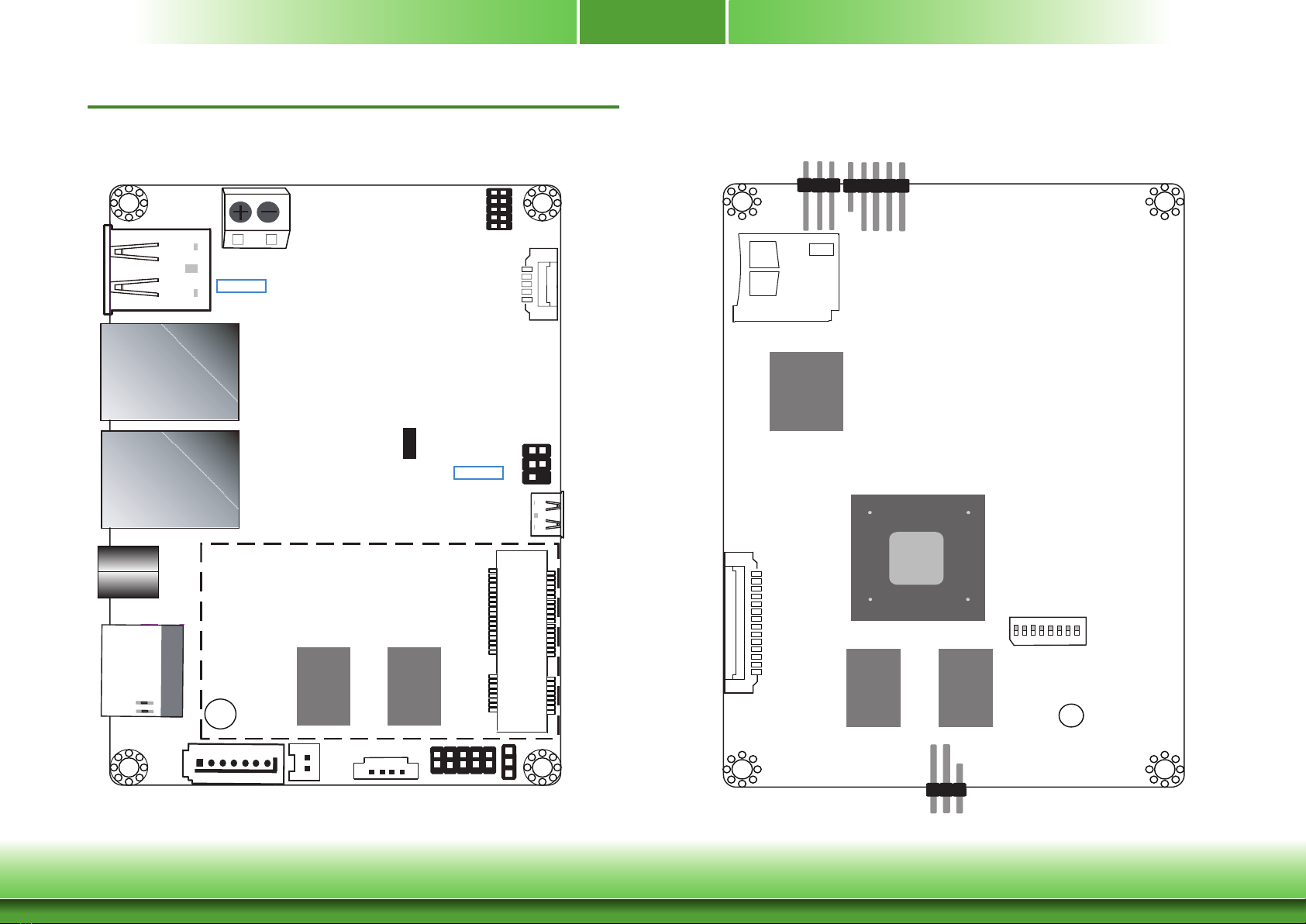
Board Layout .................................................................. 8
Block Diagram................................................................. 9
Mechanical Drawing......................................................... 9
System Memory .............................................................10
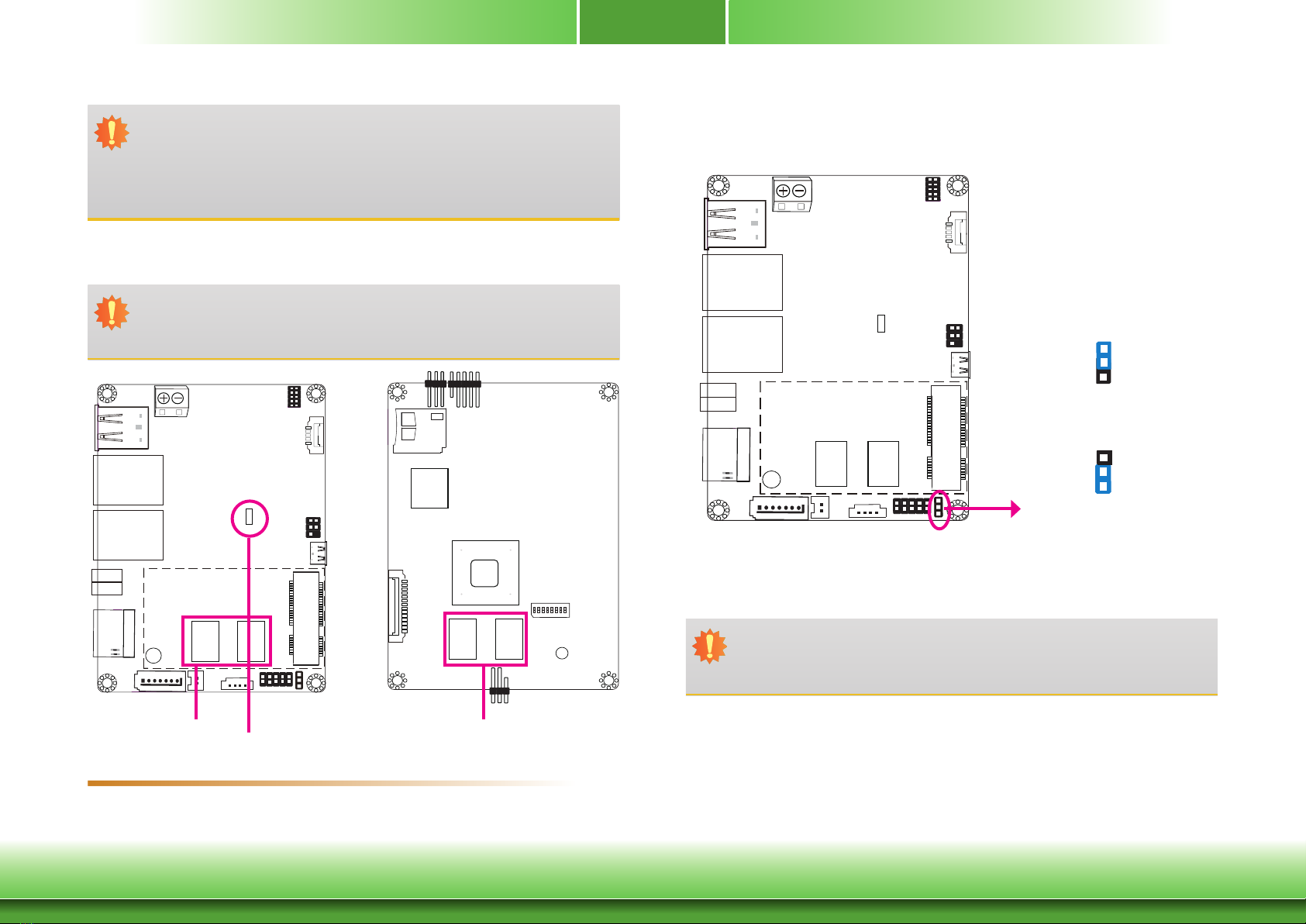
Jumper Settings .............................................................10
Panel Power Select ........................................................ 10
Boot Mode/Device Select ................................................ 11
Rear Panel I/O Ports.......................................................12
9~36V DC-in................................................................. 12
Graphics Interface ......................................................... 13
RJ45 LAN Ports ............................................................. 13
USB Ports ..................................................................... 14
Serial Port .................................................................... 14
Front Panel I/O Ports......................................................15
USB 2.0 OTG Port.......................................................... 15
Internal I/O Connectors..................................................15
Digital I/O Connector ..................................................... 15
COM (Serial) Port .......................................................... 16
Front Panel Connector.................................................... 17
SATA (Serial ATA) Connector (for i.MX6 Quad only) ........... 17
Expansion Slots............................................................. 18
I2C Connector ............................................................... 18
LVDS LCD Panel Connector ............................................. 19
Panel Backlight/SATA Power Connector............................. 19
Debug Connectors ......................................................... 20
Battery......................................................................... 20
Chapter 3 - Software User Guide................21
Introduction ...................................................................21
Check Board Type ..........................................................21
Download Images to eMMC with MFGTool .......................21
Download Uboot Images to SPI with MFGTool .................23
Download Images to SD Card with MFGTool ....................24
Software Features ..........................................................26
General Support ............................................................ 26
Linux AP/API Support..................................................... 26
Yocto Support ............................................................... 27
Android Support ............................................................ 28
Appendix A - Compatibility ......................... 30

4
Warranty
1. Warranty does not cover damages or failures that arised from misuse of the product, in-
ability to use the product, unauthorized replacement or alteration of components and prod-
uct specifications.
2. The warranty is void if the product has been subjected to physical abuse, improper instal-
lation, modification, accidents or unauthorized repair of the product.
3. Unless otherwise instructed in this user’s manual, the user may not, under any circum-
stances, attempt to perform service, adjustments or repairs on the product, whether in or
out of warranty. It must be returned to the purchase point, factory or authorized service
agency for all such work.
4. We will not be liable for any indirect, special, incidental or consequential damages to the
product that has been modified or altered.
Static Electricity Precautions
It is quite easy to inadvertently damage your PC, system board, components or devices even
before installing them in your system unit. Static electrical discharge can damage computer
components without causing any signs of physical damage. You must take extra care in han-
dling them to ensure against electrostatic build-up.
1. To prevent electrostatic build-up, leave the system board in its anti-static bag until you are
ready to install it.
2. Wear an antistatic wrist strap.
3. Do all preparation work on a static-free surface.
4. Hold the device only by its edges. Be careful not to touch any of the components, contacts
or connections.
5. Avoid touching the pins or contacts on all modules and connectors. Hold modules or con-
nectors by their ends.
Safety Measures
To avoid damage to the system:
• Use the correct AC input voltage range.
To reduce the risk of electric shock:
• Unplug the power cord before removing the system chassis cover for installation or servic-
ing. After installation or servicing, cover the system chassis before plugging the power
cord.
Important:
Electrostatic discharge (ESD) can damage your processor, disk drive and other com-
ponents. Perform the upgrade instruction procedures described at an ESD worksta-
tion only. If such a station is not available, you can provide some ESD protection by
wearing an antistatic wrist strap and attaching it to a metal part of the system chas-
sis. If a wrist strap is unavailable, establish and maintain contact with the system
chassis throughout any procedures requiring ESD protection.

5
About the Package
The package contains the following items. If any of these items are missing or damaged,
please contact your dealer or sales representative for assistance.
• One FS053 board
• One terminal block for RS485
• One heat spreader (Height: 11mm)
Optional Items
• USB 2.0 port cable (Length: 200mm, 1 x USB port)
• COM cable (Length: 250mm, 1 x COM port)
• Power cable for SATA and LCD backlight (Length: 155mm)
• Heat sink (Height: 16.8mm)
The board and accessories in the package may not come similar to the information listed
above. This may differ in accordance to the sales region or models in which it was sold. For
more information about the standard package in your region, please contact your dealer or
sales representative.
Before Using the System Board
Before using the system board, prepare basic system components.
If you are installing the system board in a new system, you will need at least the following
internal components.
• Storage devices such as a SD card and hard disk drives, etc.
You will also need external system peripherals you intend to use which will normally include at
least a keyboard, a mouse and a video display monitor.

6
Chapter 1 - Introduction
Specications
Chapter 1
Chapter 1 Introduction www.d.com
SYSTEM Processor NXP i.MX6 Cortex-A9 Dual Lite, 1.0 GHz
NXP i.MX6 Cortex-A9 Quad, 1.0 GHz
Memory 1GB/2GB SDRAM Memory Down
Single Channel DDR3L 1600MHz
Flash 4MB NOR Flash
GRAPHICS Display 1 x HDMI
1 x LVDS
HDMI: resolution up to 1920x1080 @ 60Hz
LVDS: single channel, resolution up to 1366x768 @ 60Hz
Single/Dual Displays Yocto: HDMI or LVDS (default)
Android: HDMI + LVDS (available upon request)
EXPANSION Interface 1 x Full-size Mini PCIe (PCIe/USB)
ETHERNET Controller 1 x ATHEROS AR8033 Ethernet (10/100/1000Mbps)
1 x LAN7500 Ethernet (10/100/1000Mbps)
REAR I/O Ethernet 2 x GbE (RJ-45)
Serial 1 x RS-485 (2-wire)
USB 2 x USB 2.0
Display 1 x HDMI
Front I/O USB 1 x USB 2.0 OTG Port
INTERNAL I/O Serial 1 x RS-232/422/485 (8-wire)
USB 1 x USB 2.0
Display 1 x LVDS LCD Panel Connector
SATA 1 x SATA 2.0 (up to 3Gb/s) (Quad processor only)
eMMC Supports 8GB, 16GB and 32GB eMMC onboard
SD 1 x Micro SD Slot
DIO 1 x 8-bit DIO
WATCHDOG TIMER Output & Interval System Reset, Programmable via Software from 1 to 255 Seconds
POWER Type 9~36V DC
Connector Terminal block (2-pin)
Consumption Typical: 12V @ 0.355A (4.26Watt)
Max.: 12V @ 0.631A (7.58Watt)
OS SUPPORT Yocto (1.8, default preloaded on eMMC)
Android (5.1.1)
ENVIRONMENT Temperature Operating: 0 to 60°C / -20 to 70°C
Storage: -40 to 85°C
Humidity Operating: 5 to 95% RH
Storage: 5 to 95% RH
MECHANICAL Dimensions 2.5" Pico-ITX Form Factor
100mm (3.94") x 72mm (2.83")
Height PCB: 1.6mm
Top Side: 16.15mm, Bottom Side: 4mm
CERTIFICATIONS CE, FCC, RoHS

7
Chapter 1
Chapter 1 Introduction www.d.com
Features
• DDR3L
DDR3L requires less voltage (1.35V) than DDR3 (1.5V). DDR3L SDRAM modules support
1600MHz for DDR modules.
• Storage
The board features microSD card and eMMC memory for storing system firmware. And with
the i.MX6 Quad processor, an additional Serial ATA 2.0 port is provided for storing system and
user data.
• Gigabit LAN
The Ethernet LANs are built around the Atheros AR8033 Ethernet controller
(10/100/1000Mbps) and LAN7500 Ethernet controller (10/100/1000Mbps).
• Power Failure Recovery
When power returns after an AC power failure, the system will power on automatically.
• USB
The system board supports the USB 2.0 to provide two USB host Type-A ports, one USB OTG
port and one internal pin header for one additional USB port.

www.d.com
8
Chapter 2 Hardware Installation
Chapter 2
Panel Backlight/SATA Power
5
1
DC-in
USB 1-2
USB 2.0
1
10 9
2
JTAG
Mini
PCIe
Battery
1
19
DIO Panel Power Select
(JP1)
1
SATA 2.0
(for i.MX6 Quad)
Debug
1
71
4
DDR3L DDR3L
Debug LED
1
5
2
USB 3
USB 2.0
USB OTG
COM 1
HDMI
LAN 2
LAN 1
Chapter 2 - Hardware Installation
Board Layout
Top View Bottom View
Front
Panel COM 3
1
microSD
eMMC
1 5
NXP
i.MX6
Cortex-A9
Boot Mode/Device Select
(SW5)
ON
1 2 3 4 5 6 7 8
5 9
I C
2
1
LVDS LCD Panel
1
14
DDR3L DDR3L

www.d.com
9
Chapter 2 Hardware Installation
Chapter 2
Block Diagram
NXP
i.MX6
DDR3L
Memory Down
PCIe x1
Front Panel
NOR Flash
Full-size
Mini PCIe
USB 2.0
GLAN RGMII
RS-232/422/485
RS-485
SATA 2.0 SATA 1x
SPI
SD
SD
e.MMC
USB OTG
GPIO 3.3V
USB 2.0
HDMI HDMI
LVDS LVDS
USB 1x
I2C Bus
USB 2.0
UART TEST
USB HOST
USB2517 USB HUB
USB 2x
GLAN
Mechanical Drawing
0
3.04
23.21
69.08
72
15.55
54.75
72.63
0
2.97
14.45
31.08
49
64.39
81
97.05
100

www.d.com
10
Chapter 2 Hardware Installation
Chapter 2
Jumper Settings
Panel Power Select
JP1
System Memory
Important:
Electrostatic discharge (ESD) can damage your board, processor, disk drives, add-in
boards, and other components. Perform installation procedures at an ESD workstation
only. If such a station is not available, you can provide some ESD protection by wear-
ing an antistatic wrist strap and attaching it to a metal part of the system chassis. If
a wrist strap is unavailable, establish and maintain contact with the system chassis
throughout any procedures requiring ESD protection.
Important:
The Debug LED lights red until the operating system is being accessed. Power-off the
PC then unplug the power cord prior to installing any devices. Failure to do so will
cause severe damage to the motherboard and components.
• 1GB/2GB SDRAM Memory Down
• Single Channel DDR3L 1600MHz
Features
DDR3L
1
3
1-2 On: +3.3V
(default)
2-3 On: +5V
1
3
JP1 is used to select the power supplied with the LCD panel.
Important:
Before powering-on the system, make sure that the power settings of JP1 match the
LCD panel’s specification. Selecting the incorrect voltage will seriously damage the
LCD panel.
ON
1 2 3 4 5 6 7 8
DDR3L
Debug LED

www.d.com
11
Chapter 2 Hardware Installation
Chapter 2
Boot Mode/Device Select
ON
1 2 3 4 5 6 7 8
To select the boot mode and boot device, please use finger switch SW5.
1 2 3 4 5 6 7 8
SW5
Note:
Based on different board versions, i.e. Rev. A and Rev. B, the boot device may be
pre-configured differently. Please refer to Appendix A for a thorough comparison.
Boot Device Select SW5
12345678
eMMC Note On On Off Off On On Off On
SPI Note xx xx xx On On Off Off On
SD On Off On Off Off On Off On
Boot Mode Select SW5
Boot from the fuses 7 Off, 8 Off
Serial downloader 7 On, 8 Off
Boot from the board settings (default) 7 Off, 8 On
Reserved 7 On, 8 On

www.d.com
12
Chapter 2 Hardware Installation
Chapter 2
Rear Panel I/O Ports
The rear I/O ports consist of the following:
• 1 9~36V DC-in 2-pin terminal block
• 2 USB 2.0 ports
• 2 LAN ports
• 1 serial (RS-485) port
• 1 HDMI port
• 1 USB 2.0 OTG port
9~36V DC-in
+-
This 2-pin terminal block is considered a low power solution. Connect a DC power cord to this
terminal block. Using a voltage more than the recommended range may fail to boot the sys-
tem or cause damage to the system board.
Terminal Block
USB 2.0 HDMI
USB 2.0 OTG
DC-in
COM 1
LAN 1
LAN 2
+
-

www.d.com
13
Chapter 2 Hardware Installation
Chapter 2
Graphics Interface
HDMI Port
The HDMI port carries video signals and is used to connect a LCD monitor or a digital TV that
has a HDMI port.
RJ45 LAN Ports
Features
• 1 Atheros AR8033 Ethernet controller (10/100/1000Mbps)
• 1 LAN7500 Ethernet controller (10/100/1000Mbps)
The LAN ports enable the system board to connect to a local area network with a network
hub.
LAN 1
HDMI
LAN 2
The display port consists of the following:
• 1 HDMI port

www.d.com
14
Chapter 2 Hardware Installation
Chapter 2
USB Ports
The USB device allows data exchange between your computer and a wide range of simultane-
ously accessible external Plug and Play peripherals.
The system board is equipped with 2 onboard USB 2.0 ports (USB 1-2). The 6-pin connec-
tor allows you to connect 1 additional USB 2.0 port (USB 3). The additional USB port may be
mounted on a card-edge bracket. Install the card-edge bracket to an available slot at the rear
of the system chassis and then insert the USB port cables to a connector.
Pin Pin Name
15V
2Data-
3Data+
4GND
5NC
USB 2.0
USB 2
USB 1
USB 3
USB 2.0
1 2
5
4
Serial Port
The serial port provides 2-wire RS485 communication with support of auto flow control.
1 2
COM 1
Pin Pin Name Pin Pin Name
1RS485+ 2RS485-
3

www.d.com
15
Chapter 2 Hardware Installation
Chapter 2
Front Panel I/O Connectors
USB 2.0 OTG Port
The USB 2.0 OTG port is used for USB communication.
USB 2.0 OTG
The Digital I/O connector supports 8-bit digital input/output signals to provide powering-on
function of the connected devices.
Pin Pin Name
1GPIO7
2GPIO6
3GPIO5
4GPIO4
5GPIO3
6GPIO2
7GPIO1
8GPIO0
93.3V
10 GND
Internal I/O Connectors
Digital I/O Connector
Digital I/O
1
2
9
10

www.d.com
16
Chapter 2 Hardware Installation
Chapter 2
COM (Serial) Port
ON
1 2 3 4 5 6 7 8
COM 3: RS232/422/485
COM 3
COM 3 can be selected among RS232, RS422 and RS485. RS485 communication supports auto
flow control.
The serial port is asynchronous communication ports with 16C550A-compatible UARTs that can
be used with modems, serial printers, remote display terminals, and other serial devices.
Pin RS-232 RS-422 RS-485
1DCD TX- DATA-
2DSR NC NC
3SIN TX+ DATA+
4RTS NC NC
5SO RX+ NC
6CTS NC NC
7DTR RX- NC
8RI NC NC
9GND GND GND
2
1 9

www.d.com
17
Chapter 2 Hardware Installation
Chapter 2
Front Panel Connector
ON
1 2 3 4 5 6 7 8
Front
Panel
Reset Button
This switch allows you to reboot without having to power off the system.
Power_LED
This LED indiates power status.
SATA (Serial ATA) Connector (for i.MX6 Quad only)
• 1 Serial ATA 2.0 port with data transfer rate up to 3Gb/s
The Serial ATA connector is used to connect the Serial ATA device. Connect one end of the Se-
rial ATA data cable to a SATA connector and the other end to your Serial ATA device.
Features
SATA
7
RXM
GND
TXP
TXM
GND
1
RXP
GND
Pin Pin Name Pin Pin Name
1Power Button 2Power LED
3GND 4Standby LED
5Reset Button 6Lid Button
1
2
6
5

www.d.com
18
Chapter 2 Hardware Installation
Chapter 2
Expansion Slots
Mini PCI Express Slot
The full-size Mini PCIe socket supports PCIe x1 and USB 2.0 signals and is used to install a
Mini PCIe card.
microSD Socket
The microSD socket allows you to install a microSD card for the expansion of available storage.
Mini PCIe
ON
1 2 3 4 5 6 7 8
microSD The I2C connector is used to monitor or communicate with system components.
I2C Connector
ON
1 2 3 4 5 6 7 8
I2C
Pin Pin Name
13.3V
2GND
3I2C_Clock
4NC
5I2C_DATA
2
15

www.d.com
19
Chapter 2 Hardware Installation
Chapter 2
LVDS LCD Panel Connector
Panel Backlight/SATA Power Connector
The system board allows you to connect a LCD Display Panel by means of the LVDS LCD panel
connector and the Panel Backlight/SATA power connector. These connectors transmit video sig-
nals and power from the system board to the LCD Display Panel. Panel Backlight/SATA power
connector also supplies power to the SATA drive. Connect one end of the provided power
cable to the SATA power connector and the other end to your storage device.
Refer to the right side for the pin functions of these connectors.
Pin Pin Name Pin Pin Name
1GND 2GND
3LVDS_CLK- 4LVDS_CLK+
5LVDS_Out3- 6LVDS_Out3+
7LVDS_Out2- 8LVDS_Out2+
9LVDS_Out1- 10 LVDS_Out1+
11 LVDS_Out0- 12 LVDS_Out0+
13 Panel Power 14 Panel Power
Pin Pin Name
1Panel Backlight/SATA Power (+5V)
2GND
3Panel Backlight On/O Control
4Dimming Control
5Panel Backlight/SATA Power (+5V)
LVDS LCD Panel
1
14
Panel Backlight/SATA Power
5
1
ON
1 2 3 4 5 6 7 8
LVDS LCD Panel Connector Panel Backlight/SATA Power Connector
Note:
1. DFI board's LVDS connector:
Manufacturer: E-call
Part No.: 0110-3221140
Description: Wafer connector, 14 pin, 1.25mm (pitch), White, 3.45mm (height), SMT
type, 90 degree
2. DFI board's Panel Backlight/SATA power connector:
Manufacturer: E-call
Part No.: 0110-3221050
Description: Wafer connector, 5 pin, 1.25mm (pitch), 3.45mm (height), SMT type,
90 degree, White
3. DFI board's LVDS cable:
Manufacturer: Molex
Part No.: 51021-1400
Description: 1.25mm (pitch)

www.d.com
20
Chapter 2 Hardware Installation
Chapter 2
Debug Connectors
The JTAG and debug connectors are used for debugging purposes.
JTAG
Debug
Pin Pin Name
13.3V
2UART5_RX
3UART5_TX
4GND
Battery
The lithium ion battery powers the real-time clock. It is an auxiliary source of power when the
main power is shut off.
Safety Measures
• Danger of explosion if battery incorrectly replaced.
• Replace only with the same or equivalent type recommended by the manufacturer.
• Dispose of used batteries according to local ordinance.
Battery
Connector
1
+3.3V
GND
2
Connect to the
battery connector
Battery
14
Pin Pin Name Pin Pin Name
13.3V 2JTAG _TMS
3GND 4JTAG_TCK
5GND 6JTAG_TDO
7JTAG_MOD 8JTAG_TDI
9JTAG_nTRST 10 JTAG_nRESET
Debug Connector JTAG Connector
12
9
10
Table of contents
Other DFI Motherboard manuals

DFI
DFI G586IPBS User manual

DFI
DFI CA34-SC User manual

DFI
DFI M8M051 User manual

DFI
DFI Infinity NF-ULTRA-M2 User manual

DFI
DFI NP101-D16C User manual

DFI
DFI BW051 User manual

DFI
DFI PIC-Q170/H110 User manual

DFI
DFI LANParty Jr. GF9400 T2RS User manual

DFI
DFI MB336-NRM User manual

DFI
DFI Blood-Iron P43-T34 User manual