DG Technologies DPA 5 User manual


Page 2 of 31
© 2017-2019 DG Technologies
Permission is granted to copy any or all portions of this manual, provided that such copies are for use with the DPA
product and that “© 2010-2019 DG Technologies”, (herein referred to as “DG Technologies” or “DG”), remains on all
copies.
The accompanying software, provided for use with the DPA 5 Family, is also copyrighted. Permission is granted to copy
this software for back-up purposes only.
I M P O R T A N T
To ensure your success with this product, it is essential that you read this document carefully before using the hardware.
Damage caused by misuse of the hardware is not covered under product warranty.
When using this manual, please remember the following:
This manual may be changed, in whole or in part, without notice.
DG assumes no responsibility for any damage resulting from the use of this hardware and software.
Specifications presented herein are provided for illustration purposes only and may not accurately represent the
latest revisions of hardware, software or cabling.
No license is granted, by implication or otherwise, for any patents or other rights of DG or of any third party.
DPA® and the DG® logo are registered trademarks of DG Technologies. Other products that may be referenced in this
manual are trademarks of their respective manufacturers.
The DPA Product line and the products supporting the DPA have been awarded the following U.S. Patents:
Patent #
Date
Patent Overview
6,772,248
08-03-04
Protocol adapter for in-vehicle networks.
7,152,133
12-19-06
Expanded functionality protocol adapter for in-vehicle networks.
7,337,245
02-26-08
Passing diagnostic messages between a vehicle network and a computer.
7,725,630
05-25-10
Passing diagnostic messages between a vehicle network and a computer using J1939 or J1708.
8,032,668
10-04-11
Passing diagnostic messages between a vehicle network and a computer using J1939 or J1708.
8,152,557
04-10-12
Positive locking mechanism for USB connected devices.
7,984,225
07-19-11
ASCII gateway to in-vehicle networks.
7,660,934
02-0910
ASCII gateway to in-vehicle networks.
It is essential that the user read this document carefully before using the hardware.
The DPA devices are to be used by those trained in the troubleshooting and diagnostics of light-duty through heavy-duty
vehicles. The user is assumed to have a good understanding of the electronic systems contained on the vehicles and the
potential hazards related to working in a shop-floor environment.
DG understands that there are numerous safety hazards that cannot be foreseen, so we recommend that the user read
and follow all safety messages in this manual, on all your shop equipment, from your vehicle manuals, as well as internal
shop documents and operating procedures.
Safety First
Always block drive, steer, and trailer wheels both front and back when testing.
Use extreme caution when working around electricity. When diagnosing any vehicle, there is the risk of electric
shock both from battery-level voltage, vehicle voltages, and from building voltage.
Do not smoke or allow sparks or open flames near any part of the vehicle fueling system or vehicle batteries.
Always work in an adequately ventilated area, and route vehicle exhaust outdoors.
Do not use this product in an environment where fuel, fuel vapor, exhaust fumes, or other potentially hazardous
liquids, solids, or gas/vapors could collect and/or possibly ignite, such as in an unventilated area or other confined
space, including below-ground areas.

Page 3 of 31
© 2017-2019 DG Technologies
TABLE OF CONTENTS
1INTRODUCING THE DPA 5 FAMILY .......................................................................................................5
1.1 DPA 5PRO 5
1.2 DPA 5DUAL CAN 6
1.3 COMMUNICATION LED INDICATORS 7
1.4 RP1210 OEM AND COMPONENT SOFTWARE COMPATIBILITY 7
2STANDARDS AND PROTOCOLS SUPPORTED .....................................................................................8
2.1 RP1210 DEFINED PROTOCOLS SUPPORTED 8
2.2 J2534 AND J2534-2 DEFINED PROTOCOLS SUPPORTED 8
2.3 ADDITIONAL PROTOCOLS SUPPORTED BY NATIVE DRIVERS 8
2.4 DPA 5PHYSICAL AND ELECTRICAL DETAILS 9
2.5 SYSTEM REQUIREMENTS 9
3GETTING STARTED WITH THE DPA 5 PRODUCTS ........................................................................... 10
3.1 DRIVER INSTALLATION 10
3.2 PHYSICALLY CONNECTION OF THE DPA TO THE VEHICLE 10
3.3 CHECK IF THE DPA HAS POWER 11
3.4 SETTING UP YOUR HEAVY-DUTY OEM DIAGNOSTIC APPLICATIONS 11
3.5 CONFIGURING APPLICATIONS TO USE THE DPA 5 11
3.6 ALLISON DOC 12
3.7 BENDIX ACOM DIAGNOSTICS 12
3.8 CATERPILLAR ELECTRONIC TECHNICIAN (CAT ET) 12
3.9 CUMMINS INSITE 13
3.10 CUMMINS POWERSPEC 13
3.11 DETROIT DIESEL DIAGNOSTIC LINK /DIAGNOSTIC LINK 13
3.12 DANA DIAGNOSTIC TOOL 14
3.13 EATON SERVICERANGER 14
3.14 FREIGHTLINER SERVICELINK (INCLUDING CASCADIA MODEL –DUAL CAN CHANNELS) 14
3.15 MERITOR-WABCO TOOLBOX 14
3.16 VOLVO/MACK PREMIUM TECH TOOL (PTT) –VERSION 2.X 15
3.17 VOLVO/MACK PREMIUM TECH TOOL (PTT) –VERSION 1.X 15
3.18 VOLVO/MACK VCADS 15
3.19 INTERNATIONAL TRUCK AND ENGINE 16
4SETTING UP YOUR J2534 VEHICLE OEM APPLICATIONS .............................................................. 18
4.1 J2534 CONFIGURATION UTILITY 18
4.2 GENERAL SETUP FOR J2534 OEM APPLICATIONS 19
5TROUBLESHOOTING GUIDE ............................................................................................................... 20
5.1 DETERMINE WHAT THE DPA IS DOING BASED ON LEDS20
5.2 DG UPDATE –PROGRAM OVERVIEW 20
5.3 DG UPDATE –MAIN UPDATE SCREEN 20
5.4 SUCCESSFUL CONNECT –UPDATE AVAILABLE 21
5.5 ADVANCED SETTINGS –SETTING DEFAULT TIME FOR CHECK FOR UPDATES 22
5.6 FIRMWARE UPDATE 23
5.7 DG-DPA5-9OBDII-CABLE –FOR VOLVO PTT AND OTHER OBDII APPLICATIONS 26
5.8 DG-V13-XOVER-CABLE –FOR COMPONENT APPLICATIONS (I.E.ALLISON,EATON) 26
APPENDIX A. TECHNICAL SUPPORT AND RETURN MERCHANDISE AUTHORIZATION (RMA) ..... 27
TECHNICAL SUPPORT 27
RETURN MERCHANDISE AUTHORIZATION (RMA) 27
APPENDIX B. WARRANTY INFORMATION AND LIMITATION STATEMENTS .................................... 28
WARRANTY INFORMATION 28


Page 5 of 31
© 2017-2019 DG Technologies
1Introducing the DPA 5 Family
The DPA 5 products are used to connect vehicle networks to personal computers (PCs). This allows programs written for
the PC to retrieve pertinent information such as fault codes, component information, as well as perform component level
diagnostics, tests, and component reprogramming. The DPA 5 products communicate with the PC using either a USB
cable or via Bluetooth (Class I or Class II) and comes standard with the latest Technology and Maintenance Council
(TMC) Recommended Practice (RP) RP1210-compliant drivers, as well as Society of Automotive Engineers (SAE) J2534-
compliant drivers.
1.1 DPA 5 P RO
Please note that DG Technologies provides customizable kits, so what you receive may vary.
1.1.1 Protocol LED Indicators
DPA 5 PRO Protocol LED Indicators
DPA 5 PRO Kit should include the following items:
DPA 5 PRO Main Unit
9-pin Deutsch Vehicle Cable
USB Cable with screw-in ears to secure
the cable to the DPA 5 PRO case
Quick Start Guide
Carrying Case
RED = CAN1
GREEN = SW CAN
RED = CAN2
GREEN = FT CAN
RED = CAN 3
GREEN = J1850 VPW
RED = CAN 4
GREEN = J1708/ALDL/9141
Page 6 of 31
© 2017-2019 DG Technologies
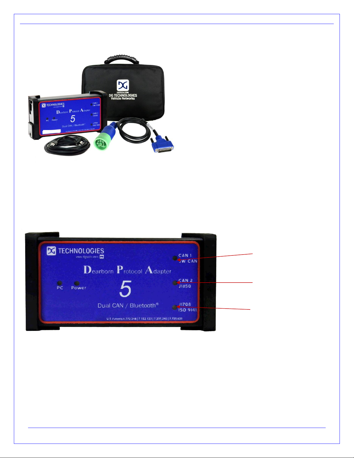
1.2 DPA 5 Dual CAN
DPA 5 Dual CAN Kit should include the following items:
DPA 5 PRO Main Unit
9-pin Deutsch Vehicle Cable
USB Cable with screw-in ears to secure the cable
to the DPA 5 PRO case
Quick Start Guide
Carrying Case
Please note that DG Technologies provides customizable kits, so what you receive may vary.
1.2.1 Protocol LED Indicators
DPA 5 Dual CAN Protocol LED Indicators
RED = CAN1
GREEN = SW CAN
RED = CAN2
GREEN = J1850 VPW
RED = UART /J1708/
GREEN = ISO9141

Page 7 of 31
© 2017-2019 DG Technologies
1.3 Communication LED Indicators
LED Label
LED Color
Description
Power
Solid RED
This LED is red when the tool is powered up.
PC
Blinks GREEN
The PC LED blinking green indicates that the computer is actively
communicating with the tool via USB.
PC
Blinks RED
The PC LED blinking red indicates that the computer is actively
communicating with the tool via Bluetooth.
PC
Alternating RED/GREEN
The PC LED blinking red and green indicates that the unit is in boot loader
mode. This occurs during the firmware update process. However, if the
firmware update process failed, the unit will remain in boot loader mode
until firmware is updated successfully. Reference the Launch the DPA
Firmware Updater Program section for information on updating the
firmware.
Protocol LED
Blinking RED or GREEN
or
Each protocol that the tool supports has its own LED. This allows the user
to see which protocols are currently being used. If there is data being sent
or received by the tool on a protocol its associated LED is blinked.
1.4 RP1210 OEM and Component Software Compatibility
The adapter you have purchased is provided with the latest Technology and Maintenance Council (TMC) RP1210
compliant interface and has been tested with the following OEM and component applications:
Allison DOC™
Bendix® ACOM
Caterpillar® Electronic Technician
Cummins® Insite™
Cummins PowerSpec
Dana Diagnostic Tool™
Detroit Diesel Diagnostic Link™
Detroit Diesel Reprogramming Station™
Eaton ServiceRanger
Freightliner ServiceLink
GM GDS2
International® InTune
International® Master Diagnostics
International® NETS
International® Auto Upgrade (AU)
Isuzu IDSS II
Mack and Volvo VCADS/PTT
Meritor-WABCO Toolbox
Navistar® Diamond Logic Builder
Navistar® HeRo
Navistar® NavKal
Navistar® NED
Navistar® ServiceMaxx
Paccar® Davie4
Vansco VMMS
ZF-Meritor TransSoft
Any application claiming RP1210 compliance should work if the application and adapter both support the same
protocol(s) and operating system(s).

Page 8 of 31
© 2017-2019 DG Technologies
2Standards and Protocols Supported
The adapter you have purchased provides more protocol and standards support than any other commercially
available diagnostic adapter.
2.1 RP1210 Defined Protocols Supported
TMC RP1210C, TMC RP1210B, TMC RP1210A
J1939
CAN (ISO11898)
IESCAN - CAN@500k/J2284/GMLAN
J2284 –CAN @500k Baud
J1708
PLC - PLC4TRUCKS Protocol - Using J1708 to PLC Converter
J1850 –RP1210A format for J1850 VPW
J1850_104K - RP1210B/C format for J1850 VPW
J1850_416K - RP1210B/C format for J1850 VPW
KWP2000
ISO9141
ISO15765
2.2 J2534 and J2534 -2 Defined Protocols Supported
SAE J1939
SAE J1708
SW CAN
CAN (Raw CAN)
J1850VPW (GM Class II)
ISO15765
GMLAN (HSCAN, SWCAN)
ISO14230 (KWP2000)
ISO9141-2
2.3 Additional Protocols Supported by Native Drivers
J2411 (GM SWCAN)
ALDL

Page 9 of 31
© 2017-2019 DG Technologies
2.4 DPA 5
Physical and Electrical Details
The following applies to both the DPA 5 Dual CAN and DPA 5 PRO hardware.
Feature
Data
Dimensions
6.1 x 2.5 x 1.2 inches
Voltage Requirements
9 –32 Volts DC
Current Requirements
250mA maximum through voltage range
Operating Temperature Range
-40 to +85C
Wired PC Communications Type
USB Version 1.1 or Higher
Wired Connection
USB Cable (up to 15 feet)
Wireless Connection
Bluetooth (DPA 5 PRO is equipped with Class 1 radio)
Vehicle-Side Connector
DB25 Female
PC-Side Connector
Standard B-Type USB Jack
PC Device Drivers
TMC RP1210C (RP1210B, RP1210A) Compliant Drivers
DG Native Drivers –J2534 Drivers
2.5 System Requirements
We recommend a computer compatible with the latest version of the TMC RP1208 (PC Selection Guidelines for
Service Tool Applications).
Item
Requirement
PC
IBM-Compatible
Processor
1GHz or Faster
RAM
4GB
USB Port
USB Version 1.1 or Higher
Operating System
Windows 7 (32-bit or 64-bit)
Windows 8 (32-bit or 64-bit)
Windows 10 (32-bit or 64-bit)
Page 10 of 31
© 2017-2019 DG Technologies
3Getting Started with the DPA 5 Products
3.1 Driver Installation
Attention!
Install the DPA 5 drivers from the website before connecting tool to your PC.
To install drivers, you must be logged into the administrator account or have administrator privileges on your PC.
If you run into problems installing the drivers, or the DPA, please review the FAQ pages at
https://www.dgtech.com/faqs/
The latest drivers and firmware are always available at www.dgtech.com/downloads. If you have any questions
about the install, please contact our technical support staff or review the FAQ pages at www.dgtech.com/faqs.
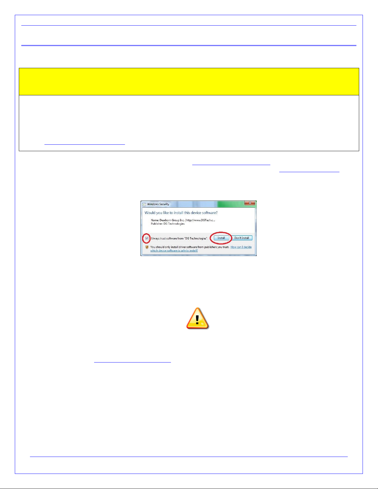
If you receive this Windows Security screen, check the Always trust software from DG Technologies and press
the Install button. Otherwise, the driver installation will fail.
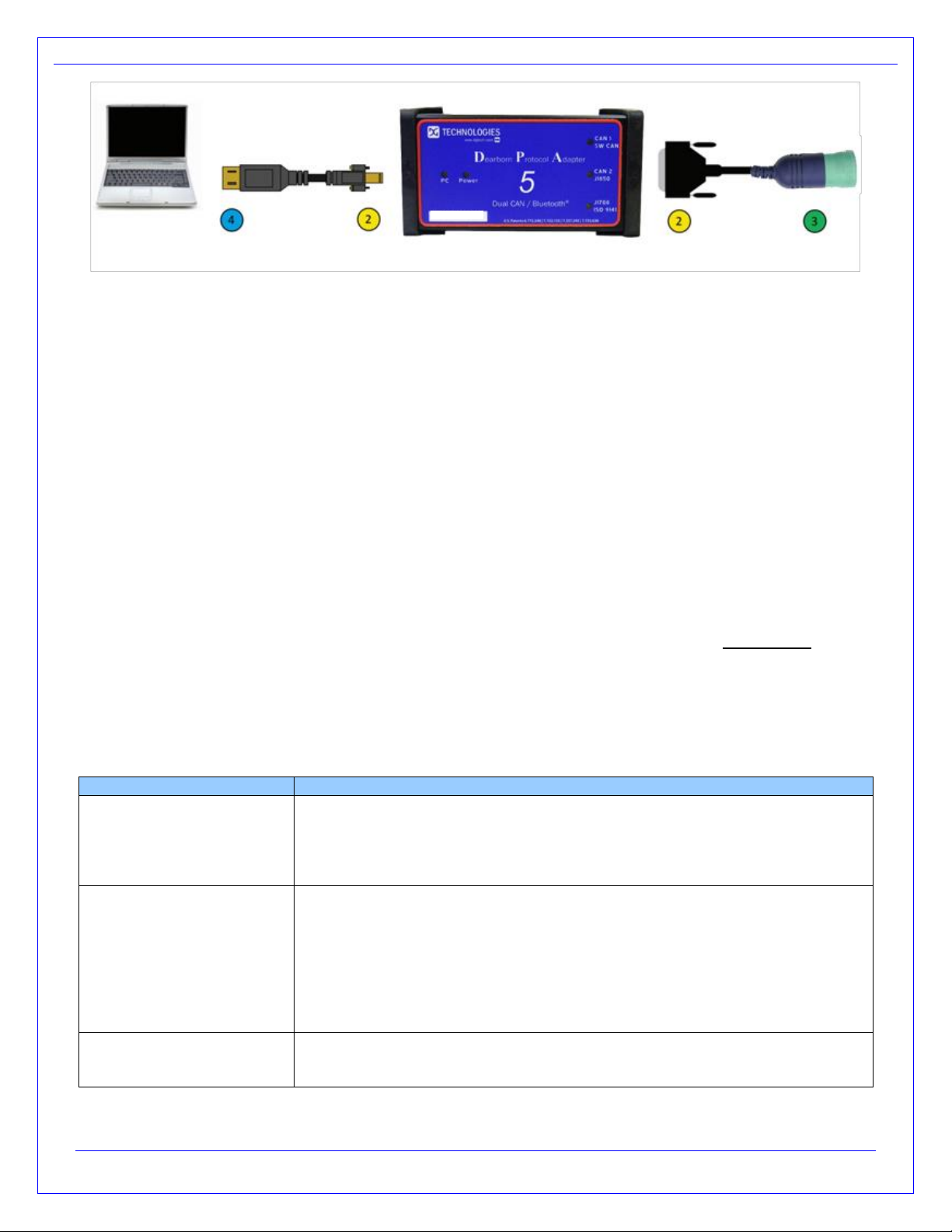
3.2 Physical Connection of the DPA to the Vehicle
It is very important to follow the steps in the connection sequence detailed below. Do not connect the diagnostic
cable with the DPA to the vehicle first! This has the potential to blow a fuse on the vehicle!
WARNING
1. Make sure that you have installed the DPA 5 software and drivers before connecting the tool to the
computer www.dgtech.com/downoads.
2. Connect the USB and the diagnostic cables to the DPA. The cables that come with the DPA can be
screwed into standoff screws on the DPA 5 frame, greatly reducing the chance of hardware failures.
3. Connect the diagnostic cable to the diagnostic port in the vehicle.
4. For reprograming you should use a wired connection; connect the USB cable to the computer. A
Bluetooth connection should only be used for diagnostic purposes. Do not connect the USB cable to the
computer if you plan on using the Bluetooth wireless connection.
Page 11 of 31
© 2017-2019 DG Technologies
Physical Connection Diagram
3.3 Check if the DPA has Power
The DPA 5 PRO may be powered via the USB port or the DB-25 pin connector. The DPA 5 Dual CAN must be
powered through the DB-25 connector. An indication of the unit having power is the Power LED will light up.
Depending on the vehicle it the key may need to be turned to turn the key to the on position before data link traffic
and / or power is supplied through the diagnostic connector.
3.4 Setting Up Your Heavy-Duty OEM Diagnostic Applications
The DPA works with all RP1210C, RP1210B, and RP1210A compliant applications that support J1708/J1587,
CAN/J1939/ISO15765, J1850 VPW (GM Class II) protocols along with many others. This section shows how to configure
the most common RP1210-compliant diagnostic applications to work with the DPA 5.
3.5 Configuring Applications to Use the DPA 5
The following examples show how to select the DPA 5 tool you will be using. Bluetooth device entries are based
on the DPA 5 Bluetooth ID (see Bluetooth manual).
Selecting an RP1210 adapter, commonly referred to as a Vehicle Datalink Adapter (VDA) varies widely from
different OEM applications; however, the terminology remains similar. The following table helps to introduce you to
the terminology and helps you to make the correct selections the first time.
You must set up every application (in their own individual way) to use the DPA.
Not all OEM applications save the adapter configuration! Some make the user selects the adapter to be used
every time the application is opened.
If You See These Terms
Select This
Vendor
API
DLL
Manufacturer
Adapter Manufacturer
DG Technologies DPA 5 Multi Application
DGDPA5MA
Device Name
Adapter Name
The description of the tool can vary widely depending upon what part of the
vendor ini file that the application is displaying. In general look for the tool name
“DPA 5 PRO” or “DPA 5 Dual CAN” that you will be using followed by the
connection type you plan on using. Common examples of entries you will see
are:
DG DPA 5 PRO (MA) USB,USB
DG DPA 5 Dual CAN (MA) USB
DG DPA 5 PRO #0000-128D-6AE6 Bluetooth,Wireless
Device Number
DeviceID
1 = DPA Dual-CAN
2 = DPA 5 PRO
160 or higher = Bluetooth Wireless DeviceID

Page 12 of 31
© 2017-2019 DG Technologies
Protocol
(Depends on Application)
Most Commonly Encountered:
J1708 (J1708/J1587)
J1939
ISO15765
CAN
3.6 Allison DOC
NOTE: Steps are for version 2017.4.0. Other versions vary slightly
1. Start program
2. Click F4 - Connect
3. Select the Correct Transmission Type
4. Uncheck Smart Connect
5. Click Connect
6. Set Translator Device to DPA 5
7. Select protocol of J1939, CAN, J1708 or J1850
8. Click Advanced Setup
9. Select Vendor of DGDPA5MA or DGDPA5SA
10. Select Protocol of J1939, CAN, J1708 or J1850
11. Select Device Name
12. Device may be grayed-out on some selections
13. Select Channel of Auto, 1, 2, 3, or 4. Channel may not appear with some selections
14. Click OK
3.7 Bendix ACom Diagnostics
NOTE: DO NOT RUN Bendix ABS Diagnostics until you have done the following:
1. Start program
2. Click on PC/check mark/Truck icon located bottom, middle-right
3. Select Device Name
4. Select green circle with check mark
5. Highlight ECU (if known) and select Start with ECU
6. If ECU not known, select Detect ECU
7. Follow on-screen instructions
3.8 Caterpillar Electronic Technician (CAT ET)
1. Start Program
2. Click Utilities Preferences Modify from the menu bar
3. Click on Communications tab (it could already be selected)
4. Select RP1210 Compliant Device
5. Click Advanced
6. Select Device Name
7. Click OK
8. Check Enable Dual Data Link Service
9. Click OK
CAT ET Notes:
1. Enable Dual Data Link. This checkbox should be checked in most cases. However, on some older
J1708 (ATA) only vehicles, ET will not work with this checkbox checked. If ET does not connect, try un-
checking, or checking this button.
2. The DPA product line does not support the CAT Data Link (CDL) protocol that is still common among
certain CAT off-highway vehicles and industrial stationary equipment. CDL is a proprietary protocol and
there are no generic adapters on the market that support this protocol.
oTo find out if your vehicle/equipment is CDL or a standard protocol (J1708/ATA, J1939), you
should look at the diagnostic connector for that equipment in the service manual.

Page 13 of 31
© 2017-2019 DG Technologies
3.9 Cummins INSITE
1. Start Program
2. Go to bottom, middle, select Add New…
3. Click Next
4. Click radio button for RP1210 Adapters and click Next
5. Select correct vendor, device, and protocol:
a. Dearborn Group DPA 5 Multi Application
b. Select Device Name
c. Auto Detect
i. If you are on an older vehicle and it does not connect, choose J1708
6. Select Datalink Adapter Connection Test, verify successful screen, click Next
7. Verify Connection Name screen appears, select Next
8. Screen prompts you to indicate whether you want to make this connection active or set up another
connection.
9. Click on make this connection active
10. Click Finish
11. Click Connect
3.10 Cummins PowerSpec
1. Start Program
2. Click on Advanced
3. Click Settings
4. Datalink Adapter:
a. DG Technologies DPA 5 Multi Application
5. Device List:
a. Select Device Name
6. Datalink Protocol:
a. Auto Detect (or choose protocol for your engine)
7. Click Save selection
PowerSpec Notes:
8. PowerSpec Version 5.5 or newer is required to use the DPA 5. Older versions of PowerSpec were not
completely RP1210-compliant.
3.11 Detroit Diesel Diagnostic Link / Diagnostic Link
3.11.1 From Windows Start Menu
1. Start Programs Diagnostic Link 8 SID configure
2. Select Device Name
3. Click OK
3.11.2 From Inside DDDL
1. Tools Options Connections Tab SID Configure.
2. Select Device Name
3. Click OK
3.11.3 If you have the Detroit Diesel Electronic Tool Suite on your desktop
1. Select Detroit Diesel Electronic Tool Suite icon from desktop.
2. Select Configure
3. Select DG DPA 5 PRO (MA) USB, USB (or DPA 5 PRO #[Bluetooth ID] Bluetooth), select OK button
4. Select Refresh
5. Click on highlighted DDDL 7 or DDDL 6 item

Page 14 of 31
© 2017-2019 DG Technologies
3.11.4 If you have the Diagnostic Link (version 6.50) icon on your desktop
1. Select Diagnostic Link icon from desktop
2. Select Look at active and inactive faults
3. To change the adapter, select Tools | Options | Interface
4. Select Device Name from Local Communication Interface drop-down list.
5. Select OK
3.12 Dana Diagnostic Tool
1. Start program
2. Under Adapter Selection, choose DG Technologies DPA 5 Multi Application: DG DPA 5 Pro (MA) USB,
USB or DG Technologies DPA 5 Multi Application: DG DPA 5 Pro (SA) USB, USB (or DPA 5 Pro
#[Bluetooth ID] Bluetooth)
3. Select Connect J1708 or Connect J1939 or Connect PLC as appropriate for your controller
3.13 Eaton ServiceRanger
1. Start Program
2. Click Go To tab
3. Select Settings
4. Under Communication Adapter choose Dearborn Group DPA 5 Multi Application
5. Under J1587 Connection choose DG DPA 5 Pro (MA) USB, USB; Protocol=J1708; Speed=9600
6. Under J1939 Connection choose DG DPA 5 Pro (MA) USB, USB; Protocol=J1939; Channel=1;
Speed=Auto
7. If connecting via Bluetooth, Select the DG DPA 5 Pro #[Bluetooth ID] Bluetooth) for both the J1708 and
J1939 device.
8. Click Apply
3.14 Freightliner ServiceLink (Including Cascadia Model –Dual CAN
Channels)
1. Start program
2. From the top menu bar, choose Admin
3. Click on Show All Devices.
4. Vendor = DG Technologies DPA 5 Multi Application
5. J1708 Device = Select Device Name
6. J1939 Device = Select Device Name
7. CAN Device
a. Click Configure
b. Select Device Name
8. Click Save Settings
3.15 Meritor -WABCO Toolbox
1. Start Program
2. Select Utilities
3. Select Adapter Selection
4. Select Vendor DG Technologies DPA 5 Multi Application
5. Select Protocol J1939 or J1708
6. Select Device Name
7. Select OK, then select X (top right) to close the Utilities Menu.
8. Select Toolbox
9. Click System Setup; then select Adapter Selection
10. Verify selections are correct, select OK
11. Click on the Truck icon to start communication

Page 15 of 31
© 2017-2019 DG Technologies
3.16 Volvo/Mack Premium Tech Tool (PTT) –Version 2.X
1. Start Program
2. Select Settings from the PTT menu
3. Go to the Communication Unit tab:
4. Highlight DG Technologies DPA 5 Single Application USB or DG Technologies DPA 5 Multi Application USB.
5. Verify radio button in default column is selected
6. Select Configuration…
7. Click on Advanced Settings, then select the down arrow on the right side of the text box
8. Highlight and click on 2 –DG DPA 5 Pro (SA) USB or DG DPA 5 Pro (MA) USB
9. Select the OK button
10. Verify DG DPA 5 Pro (SA) USB (or (MA) USB) is listed underneath Device Description:
11. Select the OK button
oWait a few minutes to establish connection. If connection doesn't occur, re-boot the PC.
oDo not select Connect immediately after PTT opens. Reading product data.... will appear after a little
bit of time while the connection is being established.
3.17 Volvo/Mack Premium Tech Tool (PTT) –Version 1.X
1. Start Program
2. Select Settings from the PTT menu
3. Go to the Communication Unit configuration tab:
a. It is here that you select the settings for each adapter that you may use. For example, if you have an
RP1210A adapter, it is here that you select which adapter, port, and protocol.
b. NOTE: This identifies the settings for each adapter. It does not select which adapter the PTT
application will use to communicate with the vehicle.
4. Go to the Comm unit selection tab:
a. It is here that you identify which adapter is to be used by the PTT application to communicate with the
vehicle. You may have to change this selection depending upon the vehicle.
b. For example, if you typically use an 88890020 adapter in direct mode, when you need to communicate
with an older vehicle you will need to change to RP1210A adapter or the 9998555 adapters,
depending upon the vehicle.
3.18 Volvo/Mack VCADS
3.18.1 From Initial VCADS Setup
1. When prompted to configure a Communication Unit select RP1210A adapter
2. When prompted for the adapter, select Device Name
3. Select USB for the Port
4. Select J1708 for the protocol
5. When prompted for the Electrical Systems
a. Click Volvo Trucks –VERSION2 and select RP1210A Adapter
b. Click Volvo Trucks –Vehicle electronics ‘98 and select RP1210A Adapter
c. Click Mack Trucks –V-MAC I/II/III, ITC and select RP1210A Adapter
d. Click Volvo Trucks –V-MAC IV and select RP1210A Adapter
6. Continue with installation
3.18.2 From Inside VCADS
1. Start Program
2. Click the Tools menu and choose Options
3. Select the Comm. Unit Configuration tab
4. Select RP1210A Adapter and then select Device Name
5. Select the correct Port (USB or Bluetooth)
6. Select J1708 for the protocol
7. Go to the Comm. Unit Selection tab:
a. Click Volvo Trucks –VERSION2 and select RP1210A Adapter

Page 16 of 31
© 2017-2019 DG Technologies
b. Click Volvo Trucks –Vehicle electronics ‘98 and select RP1210A Adapter
c. Click Mack Trucks –V-MAC I/II/III, ITC and select RP1210A Adapter
d. Click Volvo Trucks –V-MAC IV and select RP1210A Adapter
7. Click OK
3.19 International Truck and Engine
3.19.1 Master Diagnostics (MD Fleet)
1. Start program
2. Choose File MD SettingsCOM Device Window with general VDA selection
3. Select Dearborn Group DPA 5 Multi Application Window with specific port select your tools Device Name.
3.19.2 Navistar Hydraulic ABS
1. Start program
2. Choose File Hydraulic ABS Settings COM Device Window with general VDA selection
3. Select Dearborn Group DPA 5 Multi Application Window with specific port select your tools Device Name.
3.19.3 Navistar IPC
1. Start program
2. Choose File Settings COM Device Window with general VDA selection
3. Select Dearborn Group DPA 5 Multi Application Window with specific port select your tools Device Name.
3.19.4 Diamond Logic Builder (DLB)
1. Start program
2. Choose ToolsSelect Com Link Listing of adapters
3. Select Dearborn Group DPA 5 Multi Application Listing of ports select your tools Device Name.
3.19.5 Service Assistant (The new MD Fleet)
1. Start program
2. Press third button from the top along the left side (has an icon that looks like a miniature interface cable.)
a. A window comes up that says Communication Device Selection and has two drop down boxes.
b. Select Dearborn Group DPA 5 Multi Application Select your tools Device Name.
3.19.6 Navistar NavKal
1. Select NavKal icon from desktop
2. Enter username and password (if required)
3. Select Connection Select COM Link DG Technologies DPA 5 Multi Application select your tools
Device Name select J1708 or J1939 depending on engine type
4. "Searching for Engine" appears
5. Select engine type when prompted and click OK button
3.19.7 Navistar HeRo
1. Select HeRo icon from the desktop
2. Enter username and password (if required)
3. Select Connection Select COM Link DG Technologies DPA 5 Multi Application select your tools
Device Name select J1708 or J1939 depending on engine type
4. Select Connect & Scan button

Page 17 of 31
© 2017-2019 DG Technologies
3.19.8 Navistar Engine Diagnostics
1. Select NED icon from the desktop
2. Enter username and password (if required)
3. Select Connection Select COM Link DG Technologies DPA 5 Multi Application select your tools
Device Name select J1939.
4. Select Activate Com Link if connection has not started
3.19.9 Navistar ServiceMaxx J1939 or ServiceMaxx J1708:
1. Select ServiceMaxx icon from desktop
2. Enter username and password (if required)
3. Select Tools Select COM Link DG Technologies DPA 5 Multi Application select your tools Device
Name select J1939 or J1708 depending on engine type.
4. "Searching for Engine" appears
5. Select engine type when prompted and click OK button
Page 18 of 31
© 2017-2019 DG Technologies
4Setting Up Your J2534 Vehicle OEM Applications
4.1 J2534 Configuration Utility
The DPA 5 Family tools come with support for J2534 0305 and J2534. You must select the correct DPA 5 tool with the
DPA 5 J2534 0305 Config Utility before launching the light/medium duty OEM applications. This program will tell you what
J2534 protocols, API version, and Product Version is supported. You can also use the J2534 Config Utility to get the
current firmware version and specify which DPA 5 tool should be used. Two separate utilities are used. You must run
both to configure both versions.
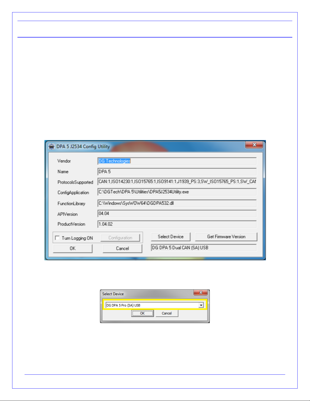
4.1.1 Selecting Which Tool to Use
Start DGTech DPA 5 DPA 5 J2534 Config Utility
Use the Select Device button to see which devices are available.
DPA 5 J2534 Config Utility
The devices will be listed in a new dialog which a drop-down selection. Select the tool you are going to use. Then select
the OK button to confirm the selection.
DPA 5 J2534 Config Utility –Select Device

Page 19 of 31
© 2017-2019 DG Technologies
4.2 General Setup for J2534 OEM Applications
Setting up and reflashing of a component using a J2534-compliant OEM is out of the scope of this manual. For more
information, select https://www.dgtech.com/oem-service-websites/
In general, there will be a screen that will appear at some point that allows a user to select a J2534-compliant Vendor and
Device for the reflashing event. When you see this type of screen, choose DG Technologies and/or the DPA 5.
The General Motors TIS2Web - J2534 Application VDA selection screen.

Page 20 of 31
© 2017-2019 DG Technologies
5Troubleshooting Guide
5.1 Determine What the DPA is Doing Based on LEDs
The LEDs on the DPA are a great way of determining what the tool is doing. Review the LED Light Meaning section to
learn more about what these lights mean.
5.2 DG Update –Program Overview
DG Update is an application that is installed with your DPA drivers. It will run (by default) once every 30 days and will
keep you up to date with the latest versions of drivers for all your DG Technologies products. With this application running
regularly and Automatic Firmware Update turned on, this will keep your DPAs up-to-date with drivers and firmware. DG
recommends our customers keep up to date so that your OEM and component manufacturer diagnostic applications run
smoothly.
DO NOT DISCONNECT POWER FROM THE DPA 5 DURING AN UPDATE!!!
The utility will run once every 30 days as a user logs on. This value is configurable, but defaults to 30 days. It can also
be invoked manually from the Windows Start Menu:
Start DGTech Utilities DG Update
DG Update –Internet Connection Required
The DG Update utility depends on successfully connecting to the Internet (to one of DG’s servers) to retrieve the
latest version information and to download the latest drivers and applications if necessary.
Many companies install firewalls and virus protection and these may block the DG server queries and responses.
If you are connected to the Internet and have issues running DG Update (getting Unable to connect to the
internet to check for updates messages), ensure that your firewall or virus protection will allow a connection to
the Internet.
5.3 DG Update –Main Update Screen
The main screen appears looking like this. Depending on which products are installed on your PC, the grid will
display pertinent information about them. When selecting DG Update from the Windows Start Menu, this is the
first screen to appear.
Other manuals for DPA 5
4
This manual suits for next models
2
Table of contents
Other DG Technologies Diagnostic Equipment manuals

DG Technologies
DG Technologies DPA 5 User manual
DG Technologies
DG Technologies Beacon User manual

DG Technologies
DG Technologies DPA XL User manual

DG Technologies
DG Technologies VSI NxGen User manual

DG Technologies
DG Technologies VSI NxGen User manual

DG Technologies
DG Technologies GRYPHON-S4 User manual


