DG Technologies VSI NxGen User manual
VSI NxGen
User Manual
© 2020 DG Technologies
Document Revision: 1.0
Document Date: January 2020
DG Technologies
33604 West Eight Mile Road
Farmington Hills, MI 48335
Phone (248) 888-2000
Fax (248) 888-9977

This document describes DG Technologies VSI NxGen. The VSI NxGen is a SAE J2534 Pass-Thru
device with its primary purpose to program automotive ECUs (Electronic Control Units).
The VSI NxGen is also useful for vehicle diagnostics, development, general design, hardware-in-
the-loop simulation and anywhere communications with a vehicle network are required.
Permission is granted to copy any or all portions of this manual, provided that such copies are
for use with the VSI- VSI NxGen product and that “© 2020 DG Technologies.”, (herein referred
to as “Dearborn Group”, “DG Technologies”, or “DG”), remains on all copies.
The accompanying software, provided for use with the VSI NxGen, is also copyrighted.
Permission is granted to copy this software for back-up purposes only.
I M P O R T A N T
To ensure your success with this product, it is essential that you read this document carefully before using the
hardware.
Damage caused by misuse of the hardware is not covered under product warranty. When using this manual, please
remember the following:
•This manual may be changed, in whole or in part, without notice.
•DG assumes no responsibility for any damage resulting from the use of this hardware or
software.
•Specifications presented herein are provided for illustration purposes only and may not
accurately represent the latest revisions of hardware, software or cabling.
•No license is granted, by implication or otherwise, for any patents or other rights of DG or of any
third party.
DG® logo is a registered trademark of DG Technologies, Inc. Other products that may be referenced in this manual
are trademarks of their respective manufacturers.
© 2020 DG Technologies

Contents
1. Introduction ......................................................................................5
1.1 VSI NxGen hardware specifications....................................................................................6
1.2 Power Connector .....................................................................................................................6
1.2.1 Powering up the hardware.............................................................................................6
1.2.2 Vehicle network connection..........................................................................................6
1.3Hardware overview..................................................................................................................7
1.3.1 DB-25...................................................................................................................................7
1.3.2 USB......................................................................................................................................7
1.3.3 12V DC.................................................................................................................................7
1.3.4 Status Indicators..............................................................................................................7
1.3.5 Status Indicators Table...................................................................................................8
2. Software Setup .................................................................................9
3. Hardware Configuration.................................................................14
3.1 First Time Hardware Connection to the PC..........................................................................14
3.2 Typical Hardware Connection to the PC...............................................................................16
3.3 Hardware Configuration Information .....................................................................................17
4. Software ..............................................................................................19
4.1 VSI NxGen Validation Utility.....................................................................................................19
4.2 DG Diagnostics OBDII................................................................................................................19
4.3 Software Development Kit (SDK)............................................................................................19
4.4 Software Update ..........................................................................................................................19
4.5 DG Update –Main Update Screen...........................................................................................20
AVT (OBDII) –Adapter Validation Tool for Light and Medium-Duty Vehicles........................................24
AVT Test Outcomes ............................................................................................................................26
Appendix A. Technical Support and Return Merchandise
Authorization (RMA)...............................................................................29
Technical Support................................................................................................................................29
Return Merchandise Authorization (RMA)........................................................................................29
Appendix B. Warranty Information and Limitation Statements.........30
Warranty Information........................................................................................................................30

Limitation Statements.......................................................................................................................30
General Limitation and Risk Assignment................................................................................30
Exclusion of Incidental, Consequential and Certain Other Damages..............................31
Limitation of Liability and Remedies........................................................................................31
Right to Revise or Update without Notice.....................................................................................31
Governance.......................................................................................................................................31
Contact...............................................................................................................................................31
Appendix C. FCC and Certification Industry Canada Information.....32
Industry Canada......................................................................................................................................32

1. Introduction
How it works: A PC is connected to a vehicle through the VSI NxGen “Pass-Thru device” to the
OBD-II J1962 connector and on to the ECUs. The VSI NxGen provides the translation interface
between the PC and the vehicle or module.
The user software application on the PC sends and receives data to the vehicle using the DG
Technologies VSI NxGen.
Provides support for: the most current version of the J2534 API (Version 04.04) and D-PDU
API (for GM Only).
Supports the following protocols:
CAN (ISO 11898, J2284)
CAN FD
FTCAN
Single-Wire CAN
ISO15765
ISO 9141
ISO 14230
J1850 PWM (Ford SCP)
J1850 VPW (both GM Class 2 and Chrysler)
SCI
Features:
•USB 2.0 connection to a PC for fast downloads. (Operates at full network speed with fast
and efficient data transfers.)
•Connects to a vehicle with an OBDII cable or a custom cable.
•Runs the SAE J1699 Vehicle Validation software.
•On or off-board J2534 module programming.
•Programming voltages –5 to 20 V in 100 mV steps.
•Useful for diagnostics or module development.

1.1 VSI NxGen hardware specifications
Dimensional
Height: 4.375 in
Width: 6.625 in.
Depth: 1.312 in.
Weight
VSI NxGen tool: 13.3 oz.
OBD II cable: 10.9 oz.
Electrical
Nominal Voltage: 12 VDC
Maximum Voltage: 27 VDC
Current consumption: Less than 200 mA at 12 VDC
Temperature range: - 40 C to + 85 C
1.2 Power Connector
The VSI NxGen can be powered via either a power jack (12V DC) OR via the supplied OBD
II cable attached to the vehicle. (See 1.3.1 for more information on 12V DC usage)
WARNING: The VSI NxGen SHOULD NOT be powered via the power jack AND the
supplied OBD II cable SIMULTANEOUSLY. Connecting to multiple power sources may
cause damage to the hardware.
1.2.1 Powering up the hardware
Once a power source has been connected, the POWER LED should light green. See
Section 1.3.4 for details.
1.2.2 Vehicle network connection
The vehicle network connection can be made by using the supplied OBD II cable or
by a custom cable to the hardware’s DB-25 (female) connector.
1.3 Hardware overview
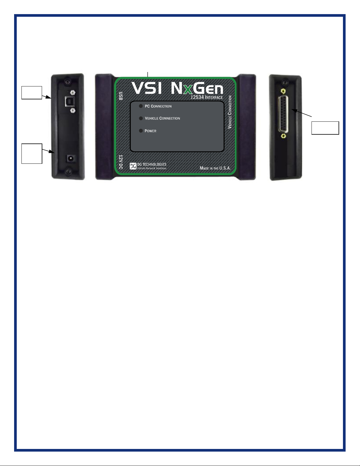
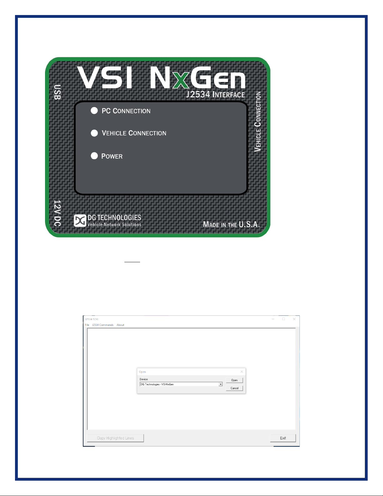
The following figures show the external features of the VSI NxGen:
Figure 1: VSI-NxGen Front & Side Views
1.3.1 DB-25
This is the connector where the OBDII cable connects and powers the VSI NxGen from
the vehicle connection.
1.3.2 USB
This is where the USB cable connects to the device to the PC.
1.3.3 12V DC
This is the external 12 volt Power Connector.
1.3.4 Status Indicators
The VSI NxGen has three status LEDs that indicate activity of the following functions:
▪PC Connection –Indicates that the VSI NxGen has established a connection to the
PC, and if the link is “active.”
▪Vehicle Connection –Indicates that the vehicle network connection is established /
active.
▪Power –Indicates that the VSI NxGen is connected to a power supply (either via the
jack plug or through a vehicle connection), and whether the unit is operating properly.
DB-25
12V
DC
USB

1.3.5 Status Indicators Table
LED Name
LED State
Description
PC Connection
Off
PC has not initialized communication with
VSI NxGen via the USB data link.
On
(Solid Red)
PC has initialized communication with VSI
NxGen via the USB or Bluetooth data link.
No bus activity.
On
(Alternating Red / Green)
Activity on the PC- VSI NxGen connection
via USB or Bluetooth data link.
Vehicle
Connection
Off
No vehicle network protocol channel has
been initialized for use.
On
(Red)
One or more vehicle network protocol
channels have been initialized for use. No
bus activity.
On
(Alternating Red / Green)
There is activity on one or more vehicle
network protocol channels.
Power
Off
No power supplied to the VSI NxGen unit.
On
(Solid Green)
Unit is powered either via the vehicle
connector or the external power jack. Unit is
operating properly.
On
(Solid Red)
Unit is powered either via the vehicle
connector or the external power jack. Unit is
not operating properly.
Bootloader
Missing
All LED’s Off
If unit is properly powered up the unit must
be serviced
Bootloader
New SW Image
Needed
All LED’s Blue
The Reflash Utility is needed
Bootloader
Reflash in
Progress
All LED’s Blink
The Reflash Utility is running
Bootloader
Manual Reboot
Needed
All LED’s Green
The user must power cycle the unit. This
should not normally happen
Table 1: LED Descriptions
2. Software Setup
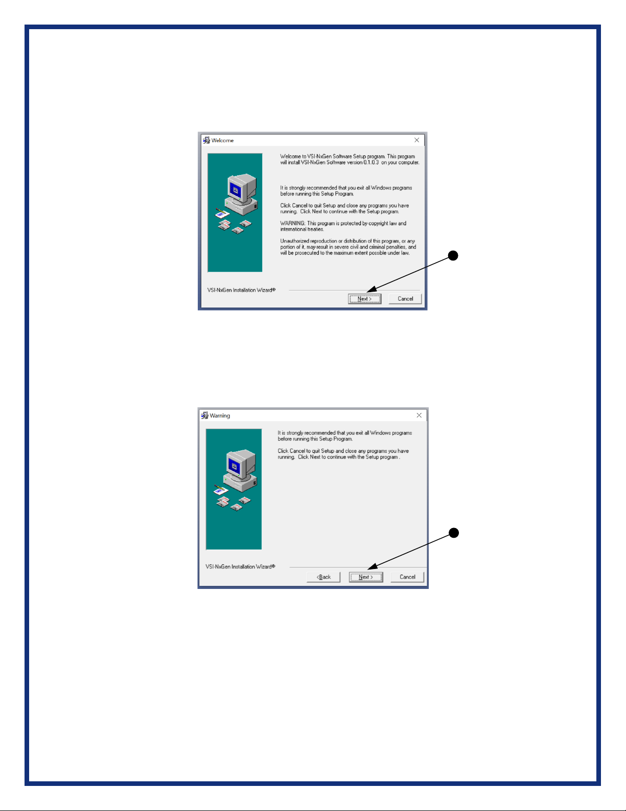
1. If it does not start automatically, locate the “Setup_VSINxGen.EXE” file and
double-click on it to start the software setup, and then click “Next”.
2. Exit all open Windows programs and click “Next” to continue.

3. Choose Destination Location for the installation. The default location is
C:\Dearborn Group Products\VSINxGen. Click “Next” to continue.
4. Click “Next” to continue.

5. Please ensure that you do not have the VSI NxGen hardware connected to the
PC’s USB port. Click “OK” to continue.
6. Click OK to continue.
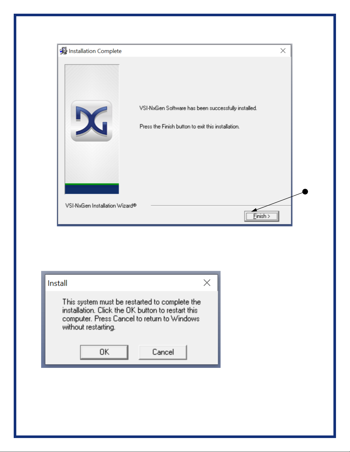
7. Installation is complete. Click “Finish”.
8. Click OK to restart your computer.

9. From the Start menu click on Product Registration.
10. Select Yes when prompted to make changes to your device.
11. From the Registration screen, complete the necessary information and select Register to
complete the process.
3. Hardware Configuration
3.1 First Time Hardware Connection to the PC
For Windows 10, an automatic installation will take place. For Windows Vista or 7, 64-bit, a
screen will display in the lower right corner of the screen indicating automatic driver installation.
Note: For Windows Vista or 7 32-bit ONLY, see below:
A failure to have the NextGen VSI device install on Windows 7 is caused by a change MS made
for Windows 7. It can be addressed by taking the following steps:
•Remove the NextGen VSI device from being plugged into a USB cable of the PC
•At the Windows ‘Start’ menu, enter cmd.exe in the ‘Search’ box
•In the list that is presented, right click on a cmd.exe and select ‘Run as administrator’
•At the command prompter, enter the following commands: o cd \Dearborn Group
Products\USBDeviceDriversVSINextGen\64Bit o InstallUSBSERSYS.bat
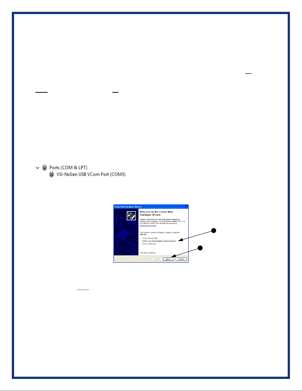
•Plug in the NextGen VSI device into a USB cable connected to the PC. From the device
Manager, it should appear as:
.. the COMx designation will vary depending on the presence of other COM devices
installed on your system
Step 1: Connect the VSI NxGen to a power source (Power adapter or powered from the
OBD II cable). Note: do not power unit from multiple sources. Power LED must be a
solid Green. Connect USB Cable to PC.
In some versions of Windows, the final step in driver installation is automatic. In others,
the Windows Found New Hardware Wizard will run to finalize driver installation. This
can take a few moments to come up.
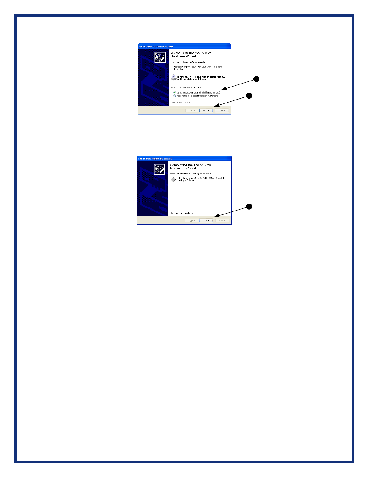
Step 2: Select “Install the software automatically” or “Yes now – and every time I
connect a new device” and click “Next”.
Step 3: Click “Finish”.
3.2 Typical Hardware Connection to the PC
Step 1: Connect the VSI NxGen to a power source (12V Power adapter or powered
from the OBD II cable). Note: Do not power unit from multiple sources. Power LED must
be a solid GREEN.
Step 2: Connect the VSI NxGen’s USB cable to the PC that the software was installed
on and note that the Power LED is a solid Green and the PC Connection LED is a solid
Red.
Step 3: Connect the OBDII cable provided to the vehicle or using an application such as
the DG 2534 SDK (Software Development Kit), shown on previous page, a user can
open a link to the hardware and connect with a protocol to a Vehicle or an Electronic
Control Module (ECU). Note: after this connection, the Vehicle Connection LED is a
solid RED.
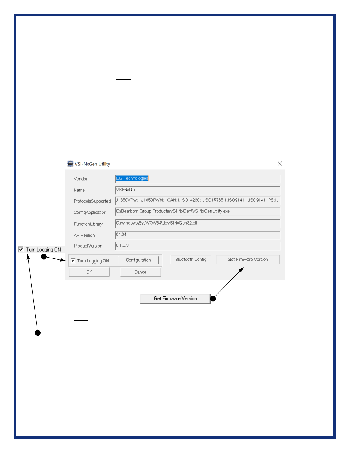
3.3 Hardware Configuration Information
By running the “VSI NxGen Config Utility”, located in Start > All Programs > DGTech
VSINxGen, a user can find out Hardware version, protocol support, and other
information.
The “Get Firmware Version” button provides the Firmware version of the VSI NxGen
hardware. Note: Do not have any other application running that uses the J2534 library.
The “Turn Logging ON” checkbox enables the Configuration button. The Configuration
button enables the user to set “Logging Type” and “Logging Method” to create VSI
NxGen DLL log. Note: Do not have any other application running that uses the J2534
library.

Protocols Supported: J1850VPW, J1850PWM, CAN, ISO9141, ISO14230, ISO15765,
SCI_A_ENGINE:1, SCI_A_TRANS:1, SCI_B_ENGINE:1, SCI_B_TRANS:1,
SWCAN_ISO15765_PS, SWCAN_PS, GM_UART_PS
VSI NxGen Version

4. Software
4.1 VSI NxGen Validation Utility
Please refer to the “DG VSI NxGen Validation Utility User Guide” found in:
Start>Programs>Dearborn Group Products>VSI-2534>Documentation.
4.2 DG Diagnostics OBDII
Please refer to the DG Diagnostics OBDII User Guide found in:
Start>Programs>Dearborn Group Products>VSI NxGen>Documentation.
4.3 Software Development Kit (SDK)
Please refer to the “DG J2534 SDK Manual” found in: Start>Programs>Dearborn
Group Products>VSI NxGen>Documentation.
4.4 Software Update
DG Update is an application that is installed with your VSI NxGen drivers. It will run (by
default) once every 30 days and will keep you up to date with the latest versions of
drivers for all your DG Technologies products. With this application running regularly
and Automatic Firmware Update turned on, this will keep your VSI NxGen up-to-date
with drivers and firmware. DG recommends our customers keep up to date so that your
OEM and component manufacturer diagnostic applications run smoothly.
DO NOT DISCONNECT POWER FROM THE VSI NxGen DURING AN
UPDATE!!!
The utility will run once every 30 days as a user logs on. This value is configurable, but
defaults to 30 days. It can also be invoked manually from the Windows Start Menu:
Start ➔DGTech Utilities ➔DG Update
DG Update –Internet Connection Required
The DG Update utility depends on successfully connecting to the Internet (to one of
DG’s servers) to retrieve the latest version information and to download the latest
drivers and applications if necessary.
Many companies install firewalls and virus protection and these may block the DG
server queries and responses. If you are connected to the Internet and have issues
running DG Update (getting Unable to connect to the internet to check for updates
messages), ensure that your firewall or virus protection will allow a connection to the
Internet.
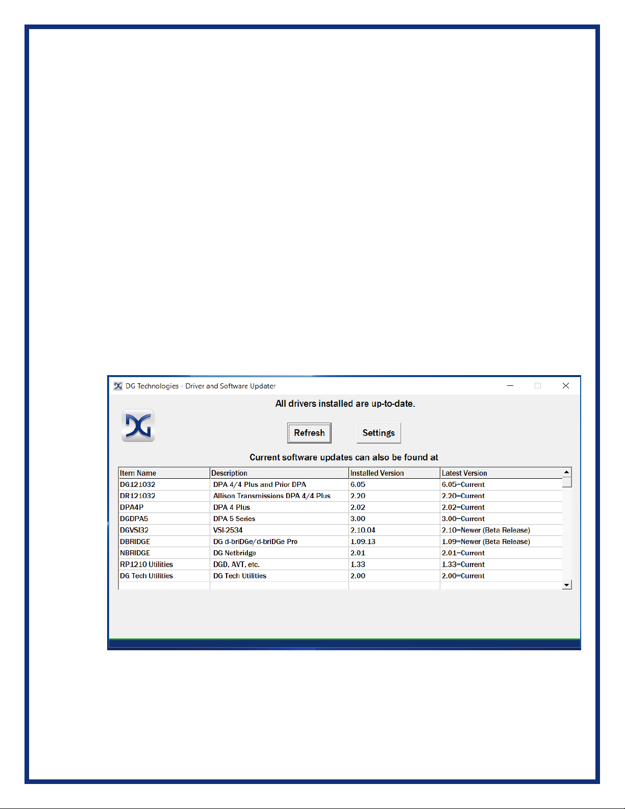
4.5 DG Update –Main Update Screen
The main screen appears looking like this. Depending on which products are
installed on your PC, the grid will display pertinent information about them. When
selecting DG Update from the Windows Start Menu, this is the first screen to
appear.
Main screen with all drivers / software up to date
Other manuals for VSI NxGen
1
Table of contents
Other DG Technologies Diagnostic Equipment manuals


