DG Technologies Beacon User manual


BEACON®MANUAL REVISED NOVEMBER 2022
2 of 35
This document is copyrighted by the Dearborn Group Inc. Permission is granted to copy
any or all portions of this manual, provided that such copies are for use with the product
provided by the Dearborn Group, and that the name “Dearborn Group Inc.” remains on all
copies as on the original.
The accompanying software, provided for use with the BEACON®interface, is copyrighted by
Dearborn Group Inc. Permission isgranted to copy this software for back-up purposes only.
I M P O R T A N T
It is essential that you read this document carefully before using the hardware.
Damage caused by misuse of the hardware is not covered under the seller’s
product warranty.
When using this manual, please remember the following:
•This manual may be changed, in whole orin part, without notice.
•Dearborn Group Inc. assumes no responsibility for any damage resulting from
any accident--or for any other reason--while the hardware is in use.
•Specifications presented herein are for illustration purposes only and are not
necessarily representative of the latest revisions of hardware or software.
Dearborn Group Inc. assumes no responsibility for any intellectual property
claims that may result from the use of this material.
•No license is granted—by implication or otherwise—for any patents or any other
rights of Dearborn Group Inc., or of any third party.
BEACON®and GRYPHON®are registered trademarks of Dearborn Group Inc. Other products
that may be referenced in this manual are trademarks of their respective manufacturers.

BEACON®MANUAL REVISED NOVEMBER 2022
3 of 35
Table of Contents
1Introduction ............................................................................................................................................5
1.1 Technical support..........................................................................................................................6
1.2 Related documents .......................................................................................................................6
2Hardware Overview / Getting Started....................................................................................................7
2.1 Contents of the BEACON® Package............................................................................................7
2.1.1 BEACON® Hardware provided.................................................................................................7
2.1.2 BEACON® Software provided ..................................................................................................7
2.2 Hardware specifications / setup....................................................................................................8
2.2.1 BEACON® hardware specifications..........................................................................................8
2.2.2 Power connection......................................................................................................................8
2.2.3 Vehicle Network connections....................................................................................................9
2.3 Hardware overview .....................................................................................................................10
2.3.1 Powering up the hardware......................................................................................................10
2.3.2 Status indicator........................................................................................................................10
2.3.3 Power jack connector..............................................................................................................11
2.3.4 USB Type A connectors..........................................................................................................11
2.3.5 USB Type B connector............................................................................................................11
2.3.6 Ethernet RJ45 connection.......................................................................................................11
2.3.7 Protocol Connections..............................................................................................................11
3Configuring the Host PC Connections.................................................................................................14
3.1 USB Connection to the PC..........................................................................................................14
3.2 Wired Ethernet Default IP address..............................................................................................14
3.3 Configuring the wired Ethernet IP Address.................................................................................15
3.4 Reset Pushbutton........................................................................................................................15
3.5 Firmware Updating......................................................................................................................16
4The Beacon Internal Web Pages.........................................................................................................18
4.1 Home Page .................................................................................................................................18
4.1.1 Login Screen ...........................................................................................................................19
4.2 Configuration Tab........................................................................................................................20
4.2.1 Date & Time ............................................................................................................................20
4.2.2 Device Name Tab....................................................................................................................21
4.2.3 Network Tab............................................................................................................................22
4.2.4 DNS Configuration ..................................................................................................................24
4.2.5 Default Route Configuration....................................................................................................25
4.2.6 Programs Tab..........................................................................................................................26
4.2.7 Password Tab .........................................................................................................................27
4.2.8 Update Tab..............................................................................................................................28
4.3 Pinouts Tab.................................................................................................................................29
4.4 Channels Tab..............................................................................................................................30
4.5 System Tab.................................................................................................................................32
4.6 Utilities Tab..................................................................................................................................33
4.7 Documentation Tab.....................................................................................................................34
Appendix A..................................................................................................................................................35
BEACON 8 channel CAN FD Version - Overview........................................................................................35

BEACON®MANUAL REVISED NOVEMBER 2022
4 of 35
This manual contains the following sections:
Section 1 –Introduction –Provides an overview of the manual, summarizing the contents of the remaining
sections and appendices. Also, provides a reference to related documentation and technical support resources.
Section 2 –Hardware Overview / Getting Started –Describes key features of theBEACON® hardware.
Section 3 –Configuring the Host PC Connections –Describes how to set up the USB and Ethernet
connections, IPaddress and how to modify the BEACON® TCP/IP parameters.
Section 4 –On Board Web Pages –Describes the onboard web page interface along with available utilities
and their use.

BEACON®MANUAL REVISED NOVEMBER 2022
5 of 35
1Introduction
The Beacon family of hardware interfaces provides remote connectivity for multiplexed automotive and
automation communication networks. These products use an Ethernet or USB connection to the user’s PC to
provide a high-speed user interface for applications such as diagnostics, monitoring, and troubleshooting, as
well as for custom applications. An embedded Linux operating system and standard Transmission Control
Protocol/Internet Protocol (TCP/IP) services ensure inter-connectivity with many existing PCs, workstations,
and network hardware systems.
The BEACON®includes the following features:
User interface
•Web-page interface
Hardware
•Processor: ARM Cortex A8, 1 GHz core speed.
•RAM: 512 Mbytes SDRAM
•NAND Flash Memory: 512 Mbytes
•Internal storage: Micro SD card, to 64 GBytes
•One RJ45 Ethernet connector
•Two USB Type AHost connectors onthefront of the unit for USB peripherals
•One USB Device Type B connector on thefront ofthe unit for connection to a Host PC
•6 Channels of High Speed CAN/ CANFD
•1 Channel Single Wire CAN
•1 Channel Fault Tolerant CAN
•2 Channels LIN
Software
•Linux OS
•On-board Web server
•TCP/IP support of standard services into the BEACON®(FTP, SSH, etc.)
•Module drivers and applications
Users can utilize one of DG’s existing PC programs, or write their own client based or stand-alone
applications for communication with the hardware.
The BEACON® utilizes the Gryphon®Communication Protocol, which is a client/server
communication protocol specification that defines the format of messages passed over a TCP
connection between the BEACON® and a client.

BEACON®MANUAL REVISED NOVEMBER 2022
6 of 35
Typical applications for the BEACON®include:
•PC-to-vehicle network adapter.
•Stand-alone node running custom applications.
•LAN gateway to one or more vehicle networks.
•End Of Line (EOL) test applications
1.1 Technical support
In the U.S., technical support representatives are available to answer your questions between 9 a.m.
and 5 p.m. EST. You may also fax or e-mail your questions to us. Include your voice telephone
number for prompt assistance.
Phone: (248) 888-2000 E-mail: techsupp@dgtech.com
Fax: (248) 888-9977 Web site: http://www.dgtech.com/tech-supp/
1.2 Related documents
For further information regarding programming with the hardware, you may wish to consult one or
more of the following resources:
Dearborn Group Inc. –Phone: (248) 888-2000
Linux-related Web sites:
Introductory Linux information; a good place to get started.
http://www.linux.com/
Linux Documentation Project - Regularly updated HOWTOs and
FAQs
http://www.tldp.org/
General Linux Q & A discussion board (with searchable archives)
http://www.linuxquestions.org/
Linux Foundation
https://www.linuxfoundation.org/

BEACON®MANUAL REVISED NOVEMBER 2022
7 of 35
2Hardware Overview / Getting Started
Please read this section before using your hardware. It describes the hardware information
necessary for successful installation and operation. Each section describes an individual hardware
configuration. Once you understand your hardware connection, move to Section 3 for connecting to
your PC via Ethernet or USB.
2.1 Contents of the BEACON® Package
2.1.1 BEACON® Hardware provided
•BEACON® unit
•12 VDC Universal A/Cpower adapter
•RJ45 Ethernet cable –The BEACON® is shipped with a standard Cat5e Ethernet cable.
(Note that the hardware can detect and switch to use either type of cable: straight-
through or cross-over.)
•Optional Wi-Fi USB adapter
•Open ended cable with HD15 male connector
2.1.2 BEACON® Software provided
Installation program with:
•32-bit C, C++ libraries and samples
•J2534 API and samples
•BEACON® User Manual (PDF)
•Various utility programs
•Hercules Analyzer Software
•Data Logger Software
The Installation Programs and Documentation are provided on a Virtual USB drive, which is
mounted to your PC when the BEACON unit is connected via a USB cable. The BEACON will
power on when it is connected to a Host PC via a USB cable.
After the BEACON has booted, you will see in Windows file explorer that a new USB mass
storage drive has appeared. It is named “BEACON_USB”. This USB mass storage drive will act
like any other USB drive. You can copy files to it or from it.
See the separate document “Software Installation Quick Start Guide” for more information.

BEACON®MANUAL REVISED NOVEMBER 2022
8 of 35
2.2 Hardware specifications / setup
2.2.1 BEACON® hardware specifications
Overall dimensions Height: 1.5 in.
Width: 6.75 in.
Depth: 5.25 in.
Electrical Typical current: = 250 mA at 12.0 VDC input
Input voltage
Minimum operational input voltage: 6 VDC
Maximum input voltage: 32 VDC
2.2.2 Power connection
The BEACON® can be powered via:
•The power jack onthe front panel(12 VDC adapter is provided).
•The specified power pins on one of the 2 network modules.
•USB connection to a Host PC Note 1
Note 1:
When the BEACON® is powered by only the USB connection the CAN and LIN circuitry will not
function. You can access the onboard web page and configure settings.
Please Note:
•For details related to the power jack, please see section 2.3.3 Power jack connector.
•For details related to powering the unit from one of the network modules, please seesection
2.3.7 Vehicle Network Connection.

BEACON®MANUAL REVISED NOVEMBER 2022
9 of 35
2.2.3 Vehicle Network connections
The BEACON® has a total of 8 CAN channels and 2 LIN channels. These network channels are built
into the Beacon. The CAN channels are dedicated to certain versions of CAN, as shown below.
•CAN channels #1 to 6 support High Speed CAN, including CAN FD
•CAN channel #7 supports Single Wire CANNote2
•CAN channel #8 supportsFault Tolerant CANNote2
Note 2: A factory option is available to convert CAN channels 7 and 8 into High Speed CAN/CAN FD
Channels. Please contact our sales department for more details about this option.
The pinout information for the vehicle connectors in your Beacon is shown in Table 1 below, and
it also may be found in the internal web pages of the Beacon.

BEACON®MANUAL REVISED NOVEMBER 2022
10 of 35
2.3 Hardware overview
Figure 1 BEACON®Connector Panel:
2.3.1 Powering up the hardware
Apply a power source to the power jack connector (see Section 2.3.3 for details) or to one of the
vehicle connectors (see Section Protocol Connections for details). The BEACON® will automatically
power on and begin the boot up process.
2.3.2 Status indicator
There is a multi-color (RGB) LED indicator on the connector panel. This LED indicator will provide
information about the state of the BEACON®.
LED colors:
•Solid Green: Normal boot up
•RGB cycling: Normal operating condition
•Alternating red/blue at 2Hz: Unit identify function has been triggered (from web page-
configuration-> device name -> Turn Identify ON)
•Solid Yellow: Default settings are being restored
•Solid Purple: Reflashing in process
•Solid Blue: Reflashing failed / other error

BEACON®MANUAL REVISED NOVEMBER 2022
11 of 35
2.3.3 Power jack connector
One way of powering the BEACON® is through the standard 2.5 mm x 5.5 mm power jack (with
positive center pin). The BEACON® operates with an input voltage between 6 and 32 VDC. Typical
operating voltage supplied by the included power adapter is 12 VDC.
Another means of powering the BEACON® is through the specified pins on one of the network
modules. (Please see section 2.3.7 for details.)
2.3.4 USB Type A connectors
The two USB type A connectors on the front panel allow the user to connect USB devices such as
Memory sticks or Wi-Fi adapters to the BEACON®.
2.3.5 USB Type B connector
Your Beacon product is equipped with a USB type B connector. The single USB type B connector on
the front panel allows the user to connectthe BEACON® to a Host PC.
2.3.6 Ethernet RJ45 connection
A CAT5e RJ45 Ethernet cable is provided with the BEACON® tool package. This cable may be
used to connect the Ethernet port on the front panel of the BEACON® to the Ethernet port on the
host PC or hub.
Either a straight through or crossover cable may be used with the Beacon. The BEACON® can
detect which cable is being used andwill accommodate the use of either cable.
The BEACON® supports 10/100 Ethernet.
2.3.7 Protocol Connections
The vehicle bus signals are provided on 2different connectors.
There is a high-density 15 pin D connector, labeled ‘Network Group A’, and a 9 pin D connector
labeled ‘Network Group B’. The pin numbers of the two connectors are shown in the table below.
You may also access pin out information on the “Pinouts” internal web page of the BEACON®.
Either the of the two connectors may be used to provide power to the BEACON® hardware.
Before applying voltage to pins marked V + IN and V –IN/GND (positive and negative), make certain
that you have the correct pin out information for the module being used to power the unit.
BEACON®MANUAL REVISED NOVEMBER 2022
12 of 35
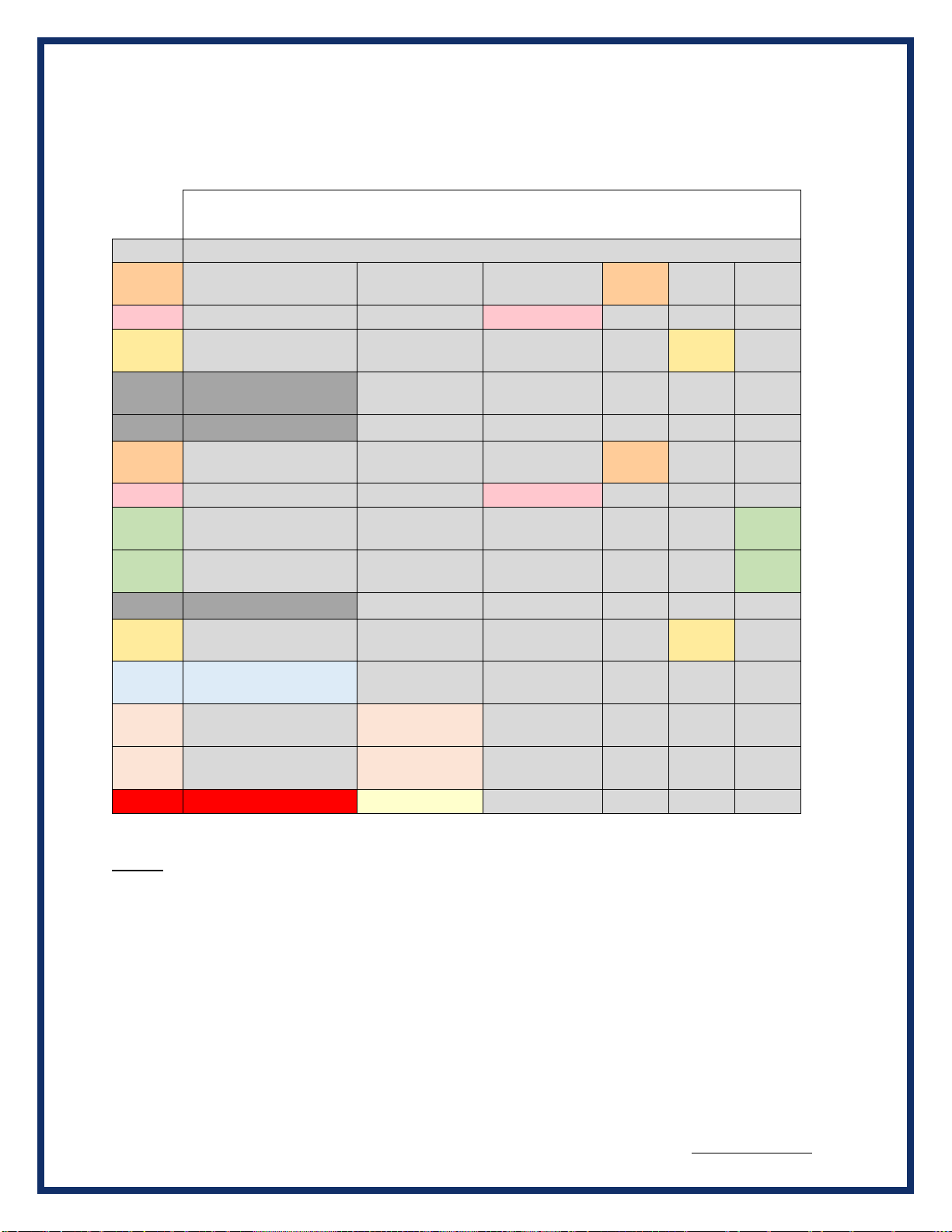
Table 1 Network Group A
HD 15 pin D connector
Network Group A
pin #
Function
1
CAN 2
Lo
2
CAN 1 Lo
3
CAN 3
Hi
4
SW CAN Lo (GND)
CAN FD 7 Lo
(note 2)
5
Signal GND
6
CAN 2
Hi
7
CAN 1 Hi
8
CAN 4
HI
9
CAN 4
Lo
10
Power GND
11
CAN 3
Lo
12
SWCAN
( Channel #7 )
CAN FD 7 Hi
(note 2)
13
FTCAN Lo
(Channel #8)
CAN FD 8 Lo
14
FTCAN Hi
(Channel #8)
CAN FD 8 Hi
15
Vin#1 (Vbatt) (fused)
Note 1:
Note 1: The Beacon may be powered by either of the Vin#1 or Vin#2 inputs. Only one of these are
required if the 12 VDC Wall Adapter is not used. Vin#1 and Vin#2 are isolated internally by blocking
diodes. See the User Manual.
Note 2: The Beacon may be ordered with a factory option to convert CAN channels 7 and 8 to
high-speed CAN/CAN FD. Please contact DG Technologies Sales Department for more details.
BEACON®MANUAL REVISED NOVEMBER 2022
13 of 35
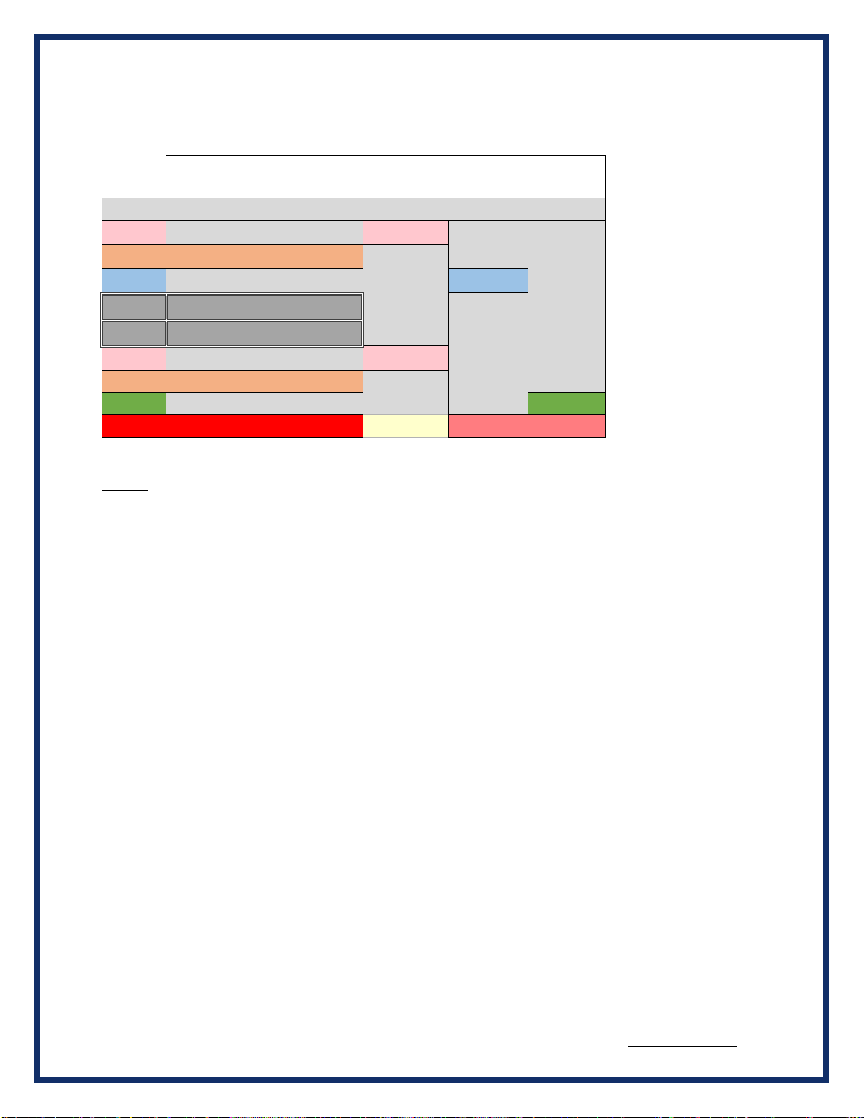
Table 2 Network Group B
9 pin D connector
Network Group B
pin #
Function
1
CAN 6 Lo
2
CAN 5 Lo
3
LIN CH 1
4
Power GND
5
Power GND
6
CAN 6 HI
7
CAN 5 HI
8
Lin CH 2
9
Vin#2 (Vbatt) (fused)
Note 3:
Vbatt for LIN
Note 3: When using the LIN channels, Vbatt (+12VDC) must be supplied on pin 9, even if the Beacon is
powered from another source.
This 12VDC input would usually be the same 12VDC source used to power the target LIN device.
Pin 9 will power the entire Beacon if 12VDC is applied. See the User Manual.

BEACON®MANUAL REVISED NOVEMBER 2022
14 of 35
3Configuring the Host PC Connections
To access information externally from the hardware, a communication connection to the BEACON®
must be established via a USB, wired Ethernet, or Wi-Fi link. This connection will allow you to send
and retrieve data, execute an onboard application, or run one of the DG applications.
3.1 USB Connection to the PC
You must have access to a PC with a USB connection. The LODESTAR supports a USB 2.0 high
speed connection and has a full-sized USB type B connector for this connection.
A standard USB cable is provided with the BEACON® package. This cable connects the USB port
on thefront panel of the BEACON® to the USB port on the host PC.
The BEACON uses RNDIS on the PC to provide a TCP/IP communication path between the
BEACON and the PC. The Beacon will act as a DHCP server and assign an address to your PC.
Every Beacon USB connection has a unique, static IP address based on an internal serial number,
which is used with the RNDIS connection. This unique IP address is printed on the serial number
label on the bottom of the Beacon package. In addition, you can see it listed on the opening page
of the internal Beacon web page. It is a fixed address and cannot be changed.
The Beacon will act as a DHCP server for the RNDIS connection. Your PC will have an IP address
automatically assigned to it during the initial connection. The address will be of the form 10.X.X.X
and the address assigned is unique to each Beacon.
For more information about the RNDIS and Windows, see the separate document titled “Beacon
RNDIS Driver Installation QuickStart”
3.2 Wired Ethernet Default IP address
Ethernet communicates by having each individual device on a network using a unique Internet
Protocol (IP) Address. Along with these addresses, there are the Netmask, Broadcast and Default
Route Addresses to configure.
The Beacon hardware has predefined default parameter values. If you are using the tool in a point-
to-point connection with your PC, these parameters typically do not need to be changed. You may
need to change these default parameters, however, if your PC is not configured as a DHCP
Client, or if you want to connect the BEACON® to a network.
The default network configuration of the Beacon is as a DHCP Server.
The following table lists the BEACON®’s default addresses:
Parameter name
BEACON® default value
IP (Internet Protocol) Address
192.168.001.001

BEACON®MANUAL REVISED NOVEMBER 2022
15 of 35
Netmask
255.255.000.000
Broadcast
192.168.255.255
Default Route
192.168.002.001
Table 3.2: TCP/IP Settings
Note: To enable communication with a BEACON® unit at this address, the IP address of
your PC must be configured to: 192.168.001.XXX, where XXX is any value other than
001.
Prior to establishing a BEACON® connection with your building’s existing LAN, you should contact
your company’s network administrator and coordinate new values for your BEACON®.
3.3 Configuring the wired Ethernet IP Address
To configure the hardware’s TCP/IP Ethernet parameters for your wired connection, access the on-
board Web server on the BEACON®, and utilize the Beacon’s Web page, which includes a
configuration tool used to set IP parameters and passwords. The page may be accessed through
any Web browser on a computer connected to the BEACON® unit.
Note: This option requires that the current TCP/IP parameters allow communication over the
network.
If communication over the network is not possible (as is often the case when reconfiguration is
required), then the TCP/IP parameters can be reset to the factory default settings (Server, with
DHCP) by using the reset pushbutton.
3.4 Reset Pushbutton
The reset pushbutton is located on the front panel of the Beacon, just to the left of the LED.
To reset the Beacon settings to factory defaults:
•Power up the unit.
•When the LED on the front panel lights (Green), press and hold the button until LED
turns Yellow. Yellow color indicates that defaults are being restored.
NOTE: The unit will also go through the restore-defaults process during the first boot, so
you'll see a Yellow LED / longer boot time during the first boot after reflashing with a new
firmware image.
Those parameters that can be reset, such as the Zeroconf name and the network settings, will be set
back to factory defaults.

BEACON®MANUAL REVISED NOVEMBER 2022
16 of 35
3.5 Firmware Updating
Firmware for the Beacon may be updated using a USB memory stick.
The reflash file will be supplied as a compressed ZIP file. The ZIP file should be extracted to a
convenient place on your PC. When the ZIP file is extracted it will produce a folder called “USBDrive”.
The contents of this “USBDrive” folder should be loaded onto the root directory of an empty USB
memory stick, formatted as a FAT 32 drive.
To initiate a USB reflash:
•With power off, insert the USB stick in one of the 2 USB ports on the front panel.
•Press and hold the pushbutton on the front panel, and keep it held while plugging power in.
•Keep holding button for ~10 sec; USB reflash will attempt to start. The LED will indicate the
progress of the reflash operation.
•Solid Purple: Reflashing in process
•Solid Green: Reflashing complete
•Solid Blue: Reflashing failed / other error
After the reflash process has completed successfully, power cycle the Beacon before using it again.
If the reflash was not succesful, you can try the proces again. The boot code within the unit is ot
modified or deleted during the reflash process.
! Note that the reflash process does erase the contents of the internal uSD memory card, including
any data or user programs stored there. Please be sure to back up any data or programs that need to
be saved, before initiating the reflash process.

BEACON®MANUAL REVISED NOVEMBER 2022
17 of 35

BEACON®MANUAL REVISED NOVEMBER 2022
18 of 35
4The Beacon Internal Web Pages
The Beacon hosts an internal web page that allows you to control many aspects of the Beacon and
to get information about the Beacon. The following sections will walk you through the internal web
pages and explain the various items. Please note that due to feature enhancements and software
updates youmay see slightly different versions of the web pages described below.
To access the internal web pages, use any web browser on your PC, such as Firefox, to access the
Beacon. Simply type the Beacon’s IP address into the address bar of the browser.
The Home page of the Beacon webpage will appear:
4.1 Home Page

BEACON®MANUAL REVISED NOVEMBER 2022
19 of 35
Next, click on Configuration. Once you enter this section, a box will prompt you for a user name and
password.
Please note: All inputs are case sensitive, and this password is the same as the default root
password.
4.1.1 Login Screen
The default user name is sysadmin; the default password is dgBeacon
Once logged in, the DG Beacon System Administration page will appear. On this page, you may:
access the DG Beacon Configuration page, configure the connection parameters, change the time
and date, or change the sysadmin password.
The first entry is Time and Date. The other entries are: Zeroconfig Name & Device Locator, DNS
Configuration, Default Route Configuration, Network Configuration, Startup Programs / Services,
Change Sysadmin Password, and Optimization.
BEACON®MANUAL REVISED NOVEMBER 2022
20 of 35
4.2 Configuration Tab
The configuration tab is the section for setting system parameters for the Beacon.
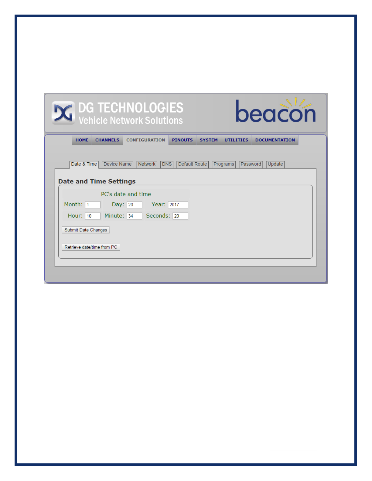
4.2.1 Date & Time
•Set Date and Time –You can either have the Beacon take the Date and Time from the
host PC, or you can enter the new values manually. When you are done updating the
Date and Time click Submit Date Changes. The new values and confirmation will then
appear on the display.
Table of contents
Other DG Technologies Diagnostic Equipment manuals

DG Technologies
DG Technologies DPA XL User manual

DG Technologies
DG Technologies DPA 5 User manual

DG Technologies
DG Technologies VSI NxGen User manual

DG Technologies
DG Technologies DPA 5 User manual

DG Technologies
DG Technologies VSI NxGen User manual

DG Technologies
DG Technologies GRYPHON-S4 User manual


