DGFLOW DGB MV 30 Installation instructions

1
DGBOX
rev. 1602
Inverter electronic control panels
for single pumps or pumping units
OPERATOR’S AND MAINTENANCE MANUAL
Model V in V out A P (kW) P (HP)
DGB MV 30
3 ~ 400V 3 ~ 400V
8 3 4
DGB MV 55
3 ~ 400V 3 ~ 400V
14 5,5 7,5
DGB MV 75
3 ~ 400V 3 ~ 400V
18 7,5 10
DGB MVF 30
3 ~ 400V 3 ~ 400V
8 + 8 3 + 3 4 + 4
DGB MVF 55
3 ~ 400V 3 ~ 400V
14 + 14 5,5 + 5,5 7,5 + 7,5
DGB MVF 75
3 ~ 400V 3 ~ 400V
18 + 18 7,5 + 7,5 10 + 10
DGB MW 30
3 ~ 400V 3 ~ 400V
8 + 8 3 + 3 4 + 4
DGB SV 30
3 ~ 400V 3 ~ 400V
8 3 4
DGB SV 55
3 ~ 400V 3 ~ 400V
14 5,5 7,5
DGB SV 75
3 ~ 400V 3 ~ 400V
18 7,5 10
10154507A .03 - 170530
EN

2
INDEX
PART 1 – QUICK INSTALLATION GUIDE
SAFETY STANDARDS 3
INSTALLATION 3
POWER CONNECTIONS PRESSURE AND FLOW SIGNAL CONNECTIONS 3
INPUT / OUTPUT SIGNAL CONNECTIONS 5
INPUT CONNECTIONS 5
OUTPUT CONNECTIONS 5
MASTER-SLAVE CONNECTIONS 5
STARTING UP 6
ACCESS TO MAIN MENU AND PARAMETER MENU 6
SELF-LEARING CONFIGURATION 7
MAIN MENU AND PARAMETER MENU 8
SETTING THE PARAMETERS REQUIRED FOR OPERATION 9
Settin the system pressure and the rated current 9
Checkin the direction of rotation of the motor 10
Checkin the motor frequency (default 50 Hz) 11
Checkin the maximum workin frequency (default 50 Hz) 11
Determination of the shutdown frequency 11
settin the full scale of the pressure sensor 11
Confi uration of the flow sensor 11
CONTROL OF DRY RUNNING IN APPLICATIONS WITHOUT FLOW SENSOR 12
TEST 13
ALARMS 14
PARTE 2 – USER’S MANUAL
PRODUCT DESCRIPTION 15
GENERAL TECHNICAL DATA nd WORKING LIMITS 17
DIMENSIONS AND WEIGHTS 17
MULTI-PUMPS UNITS 18
models nd product identific tion code 19
SURGE TANK 20
SAFETY PRESSURE SWITCH 20
FUNCTIONING 21
1. CONFIGURATION 21
1.1. BASIC CONFIGURATION (BASE SETUP) 22
1.2. ADVANCED CONFIGURAZIONE ( ADVANCED SETUP) 23
1.3. HARDWARE CONFIGURATION (HARDWARE SETUP) 27
1.4. MAINTENANCE (MAINTENANCE) 31
2. TEST 32
3. WORKING 33
4. OUT OF SERVICE 34
5. UPDATING 35
STARTING UP 37
TROUBLESHOOTING 38
WARRANTY 40
DISPOSAL 40
DECLARATION OF CONFORMITY 40

3
SAFETY STANDARDS
S fety import nt instructions.
This symbol warns that failure to comply with the prescription leads to a risk of electric shocks.
This symbol w rns th t f ilure to comply with the prescription le ds to risk of injury/d m ge to persons/objects.
Before inst ll tion nd use of the product, re d this m nu l completely nd thoroughly. Inst ll tion nd
m inten nce must be c rried out by qu lified st ff, responsible for performing the hydr ulic nd electric connections ccording
to the pplic ble St nd rds in force. The m nuf cturer declines ll responsibility for d m ge deriving from improper use of the
product nd is not li ble for d m ge c used by m inten nce or rep irs th t re c rried out by unqu lified st ff nd/or using
non-origin l sp re p rts. The use of non-origin l sp re p rts, t mpering or improper use, m ke the product w rr nty null nd
void.
During first installation make sure that:
- the electric power supply network is not live
- The electric power supply network is protected by ground connections in compli nce with the St nd rds.
When carrying out maintenance:
- the electric power supply network is not live
- Before removing the inverter cover or st rting interventions on it, the system must be disconnected from the m ins
electricity nd you must w it for 5 mins until the intermedi te circuit condensers, which c n re ch volt ges of up to 800V, h ve
the time to disch rge vi the built-in disch rge resistors.
- do not disconnect the pumps if DGBOX is in oper tion; before you disconnect the pumps, stop the control nd disconnect the
power supply.
Emergency stop
An emergency stop c n be performed while the inverter is running, by pressing the START/STOP key.
In p r llel inverters inst ll tions, only the MASTER inverter stops the whole system.
INSTALLATION
DGBOX must be installed in accordance with the following conditions:
in ventil ted room, protected from the elements nd from exposure to the sun, the side
dist nce nd height off floor re not less th n those indic ted in “DIMENSIONS AND WEIGHT”,
to llow proper unit cooling
ne r the pump - IMPORTANT: FOR APPLICATION WITH LONG CABLE BETWEEN THE INVERTER
AND MOTOR, PLEASE CONSIDER FITTING AN ELECTRONIC FILTER
In vertical position
POWER CONNECTIONS PRESSURE AND FLOW SIGNAL CONNECTIONS
Before m king the connections, m ke sure th t the ends of the line wires re not live.
M ke sure lso th t the electric power supply network is protected by therm l m gnet nd differenti l
protections ccording to the pplic ble St nd rd in force. The differenti l switch must be high-sensitivity
type (30 mA in cl ss A for domestic pplic tion, cl ss B for industri l pplic tions). Ground connections
must be in compli nce with St nd rds.
The power supply c ble must h ve 4 wires (3 ph se + ground).
The connection c ble between the inverter nd the motor pump must h ve 4 le ds (3 ph se le ds + E rth)
nd be suit bly shielded to comply with EMC st nd rds.
The c ble must be sized to curb ny power volt ge drop within 3%.
IMPORTANT: FOR APPLICATION WITH LONG CABLE CONSIDER FITTING AN ELECTRONIC
FILTER TO PREVENT POWER PEAKS AND WAVE DISTORSIONS GENERATED BY LONG CABLES.

4
DESCRIPTION OF THE MAIN COMPONENTS
LINE
PUMP 1
PUMP 2
U V W GND R S T GND
U V W GND
+Vdc+Vdc
4-20 mA
flow C
flow NO
GND
rown
lack
grey
white
lue
TEEVALVE
1
2
3
4
56789
10
11
12
+Vdc+Vdc
4-20 mA
flow C
flow NO
GND
PIN 1 +
PIN 2 -
DANFOSS
PRESSURE SENSOR
( DANFOSS )
PRESSURE SENSOR
+
FLOW SENSOR
( TEEVALVE )
1. Disconnection switch
2. Therm l m gnetic switch / fuse-c rrier module
3. Inverter 1 output termin l bo rd
4. cont ctor with therm l motor protection (fixed speed pump)
ATTENTION: set the protection of the thermal relay to the rated current of the pump
2 (fixed speed pump)
5. input sign l termin l bo rd 1 ( n logue1 + flow sign l 1)
6. input sign l termin l bo rd 2 ( n logue2 + flow sign l 2)
7. digit l input sign l termin l bo rd IN1 nd IN2
8. digit l output sign l termin l bo rd OUTPUT1 nd OUTPUT2
9. sign l termin l bo rd RS 485
10.USB port
11.keybo rd / displ y screen
12.termin l cl mps fixing b r (DIN st nd rd)

5
INPUT / OUTPUT SIGNAL CONNECTIONS
INPUT SIGNAL CONNECTIONS
IN 2
4-20 mA
Flow C.
Flow N.O.
0 V
+ Vdc
4-20 mA
Flow C.
Flow N.O.
0 V
PRESS/FLOW 1 RS485
+ Vdc
2 - C
+ Vdc
0 V
IN 1
PRESS/FLOW 2
2 - N.O.
2 - N.C.
D +
D -
1 - C
1 - N.C.
1 - N.O.
INPUT OUTPUT
12
-permits connecting two input sign ls of the
cle n-cont ct type
-see p r m. INPUT 1 CONFIG
-see p r m. INPUT 2 CONFIG
- If the cont ct of the sensor (eg. level probe) is
open, the oper tion is inhibited
- Oper ting current is 5 mA for e ch input
-M x c p city from Vdc is 100 mA.
-
The power volt ge supply (+ 24 Vdc) CANNOT
be used to supply extern l devices.
OUTPUT SIGNAL CONNECTIONS
IN 2
4-20 mA
Flow C.
Flow N.O.
0 V
+ Vdc
4-20 mA
Flow C.
Flow N.O.
0 V
PRESS/FLOW 1
RS485
+ Vdc
2 - C
+ Vdc
0 V
IN 1
PRESS/FLOW 2
2 - N.O.
2 - N.C.
D +
D -
1 - C
1 - N.C.
1 - N.O.
INP
UT
OUTP
UT
max 5A
250 V
max 5A
250 V
1
2
- 2 rel y outputs re v il ble
- These c n be connected both with NO
logic nd with NC logic
- see. p r m. OUTPUT 1 CONFIG
- see. p r m. OUTPUT 2 CONFIG
- The m x lo d which c n be connected is
2 A t 250 V c
-
the c ble must h ve 2 le ds nd
minimum cross-section of 0.5 squ re
mm
MASTER – SLAVE CONNECTIONS
permits connection nd communic tion with extern l devices by me ns of st nd rd RS485
S1
S3 (Vc)
CS3 (Vc)
j5
j4
+24Vdc
S2
Gnd
S3 (Vac)
I/OAUXILIARY
Gnd
D-
D+
+ 24Vdc
S1
Gnd
S2
54
32
132
1
CS3 (Vac)
12 3
D+
D-
Gnd
6
Rs485 OUT
Rs485 IN
1 2 36543213211 2 3 4 5
PRESS/ FLOW1
54321
USB
+ Vdc
Flow N.O.
4-20 ma
Flow C.
+ Vdc
+ Vdc
In1
In2
1-C
1 - N.C.
D+
D-
Gnd
2 - C
2-N.C
2 - N.O.
PRESS/ FLOW2 INPUT OUTPUT Rs 485
Gnd
4-20 ma
Flow C.
Flow N.O.
Gnd
1 - N.O.
To operate the system MASTER / SLAVE is necessar to address the pump 2 to inverter SLAVE.
to address the pump 2 to inverter SLAVE set the parameter 3.2 PUMP 2 CONFIG = 3 (EXT. INV. 2)
The other parameters are set in SELF-LEARNING or they can be set manually
1.5 PUMP 2 CURRENT (SLAVE pump protection) nd 1.6 PUMP 2 ROTATION
2.8 MIN POWERF2 = minimum power f ctor of the pump 2 for protection g inst dry running
2.11 POWERF TIME = en bles protection g inst dry running for COSFI.
MASTER
BOARD
SLAVE
BOARD

6
STARTING UP
Before running, this M nu l must h ve been c refully re d nd the instructions followed; wrong
settings nd oper tions re thus prevented th t could c use oper ting f ults.
After performing the oper tions described in the INSTALLATION ch pter, the inverter c n be st rted.
Before starting the system the pumps must be primed (filling and air bleeding).
When DGBOX is energised, it enters the STARTING phase which lasts 5 seconds fter which DGBOX
returns to the s me oper ting conditions in which it w s when it w s l st switched off (in WORK mode
or OUT OF SERVICE mode).
During the STARTING phase DGBOX c n be switched to OUT OF SERVICE mode or SELF-LEARNING
mode s described below:
Power
network
STARTING
phase
(5 sec.)
w iting
WORK mode if DGBOX w s in ON
condition t l st switch-off
OUT OF SERVICE mode if DGBOX w s in
OFF condition t l st switch-off
pressing
START / STOP
OUT OF SERVICE mode (suitable for
manual configuration)
pressing
ENTER
SELF-LEARNING mode (Wiz rd)
-To manuall configure DGBOX
see “ACCESS TO MAIN MENU AND PARAMETER
MENU” in this pa e
-To configure DGBOX in SELF-LEARNING
see “SELF-LEARNING CONFIGURATION”
at pa e 7.
ACCESS TO MAIN MENU AND PARAMETER MENU
in "MAIN MENU AND PARAMETER MENU" – p ge 8 - re highlighted parameters that must be
configured for the proper functioning of DGBOX (c se referred to single pump)
These p r meters re described in the section "SETTING THE PARAMETERS REQUIRED FOR
OPERATION” – p ge 9
to access the MAIN
MENU press the button
SET for 3 sec.
to
-scroll the MAIN MENU
-scroll the PARAMETER
-modify the p r meter v lues
use the keys
To
access and ex
it
the
MENU nd the
p r meter use the
keys

7
SELF-LEARNING CONFIGURATION
DGBOX permits setting all the parameters required for self-learning:
S tartin g ..... . (O FF)
5 s
Pre ss EN TER fo r WIZ ARD
1 . 0 -1 5 . 0
Bar
3 .5
P1
1 / 8W IZ A RD
Selec t
w o rk in g Press ure
(ENTER)
(ENTER)
Pu m p no m inal
c u rr en t
Selec t
W IZ A RD 2 / 8 CU1
1 4 .0
A
1 . 0 -1 8 . 0
Ro 1
3 / 8W IZ A RD
Pu m p 1 Ro t at io n
(Self Learn ing)
Pu sh T est f o r st art
(ENTER)
C . W
(ST O P)
W IZ A RD
3 0 Hz
2 .2 P
4 .5 A
W IZA RD
(ST OP)
Learnin g 1 /2 . .. O K
Learnin g 2 / 2 .. . 5 s Learnin g 2 /2 . .. O K
Learnin g 1 / 2 ... OK
(ENTER)
W IZA RD
CO M PLETED
A .C.W
Ro1
4 .5 A
2 .2 P
3 0 Hz
ST OP f o r Ex it f o r Ex itST OP
Learnin g 1 / 2 .. . 5 s
0 -1 0
0
P1 s
4 /8
W IZA RD
Selec t
Pressu re Sen sor
Ran g e
(ENTER)
Bar
s en s or
(ENTER)
Flo w sensor
presence ?
W IZ A RD 5 / 8 Fw S
0
NO
8 /8
W IZA RD
Co n f ig u ra t io n
(ENTER)
CO M PLETED
EN TER
f o r
STA RT
(ENTER)
W IZ A RD 8 /8
Pu m ps:2
V ariab le Sp eed: 2
P1 :8 A - CW
P2 : 10 A - A CW
8 /8
W IZA RD
(ENTER)
M in Pf : 0 . 8
Fr eq Of f : 3 5 h z
Flo w Sen sor: 0
Press Sen sor: 1 6 Bar
6 /8
W IZ A RD
OFF Freq uen c y
(ENTER)
(ENTER)
W IZ A RD 7 /8
3 /8 3 /8 3 /8
Se sen sore di Flusso = 0
Se sensore di Flusso > 0
STA RT
f o r
EN T ER EN T ER
f or
STA RT
3 /83 /83 /8
Learnin g 1 / 2 .. . 5 s
ST OP f o r Ex itf o r Ex itST OP
3 0 Hz
2 .2 P
4 .5 A
Ro2
A .C.W
CO M PLETED
W IZA RD
(ENTER)
Learnin g 1 / 2 ... OK
Learnin g 2 /2 . .. O K
Learnin g 2 / 2 .. . 5 s
Learnin g 1 /2 . .. O K
(ST OP)
W IZA RD
4 .5 A
2 .2 P
3 0 Hz
W IZ A RD
(ST O P)
C . W
(ENTER)
Pu m p 2 Ro t at io n
(Self Learn ing)
Pu sh T est f o r st art
W IZ A RD 3 /8 Ro 2
com p re solo se ho inverter nche su pom p 2
(Self Learn ing)
Pu sh T ES T f o r st a rt
(ENTER)
P 3 .0
W IZA RD 6 /8
Bar
3 0 . 0 Hz
Learnin g .. .. 1 0 s
OFF Freq .
3 0 . 0
4 0 . 0 Hz
OFF
Frequenc y Bar
6 /8W IZ A RD
P 3 .0
(ENTER)
OFF
Frequenc y
3 0 . 0 Hz
CO M PLETED
7 /8
W IZA RD
(ENTER)
Pu sh T ES T f o r st a rt
(Self Learn ing)
M in P Fac t or
Learnin g .. .. 1 0 s
(ENTER)
W IZA RD 7 /8
CO M PLETED 0 .7 0
M in
Pow er
Fa c t or
0 .7 0
M in Pf
0 .8 5 Pf
Fa c t or
M in
Pow er
0 .8 0
Bar
P 3 .0 P 3 .0
Bar
Prem e ndo EN TER m e m orizzo il v lore ttu le
Prem e ndo EN TER m e m orizzo il v lore ttu le
Prem end o EN TER p ss o sch erm t 8/8
Prem end o EN TER p ss o sch erm t 7/8 Prem end o EN TER p sso sc herm t 7/8
Prem end o EN TER p sso sc herm t 8/8
Prem end o EN TER es co d l w iz rd Prem end o EN TER esco d l w iz rd Prem end o EN TE R es co d l w iz rd
1 .0 -1 8 .0
A
1 4 .0
CU2
2 b /8
W IZA RD
Selec t
Pu m p 2 no m inal
current
(ENTER)
To ccess WIZARD press ENTER within 5 seconds from DGBOX
switch-on
Select the WORKING PRESSURE using the arrows UP/DOWN nd
confirm by pressing ENTER
Select the PUMP 1 RATED CURRENT using the arrows UP/DOWN
nd confirm by pressing ENTER
If present, Select the PUMP 2 RATED CURRENT using the arrows
UP/DOWN nd confirm by pressing ENTER
Select the PRESSURE SENSOR FULL SCALE using the arrows
UP/DOWN nd confirm by pressing ENTER
OPEN A TAP (e.g. 10 l/min) nd press TEST TO ENABLE THE
PROGRAM TO DEFINE THE CORRECT DIRECTION OF PUMP 1
ROTATION
OPEN A TAP (e.g. 10 l/min) nd press TEST TO ENABLE THE
PROGRAM TO DEFINE THE CORRECT DIRECTION OF PUMP 2
ROTATION (if present)
OPEN A TAP (e.g. 10 l/min) nd press TEST TO
ENABLE THE PROGRAM TO DEFINE THE PUMP 1
( nd 2 if present) SWITCH-OFF FREQUENCY
CLOSE ALL TAPS (flow = 0) nd press TEST TO
ENABLE THE PROGRAM TO DEFINE THE MINIMUM
PUMP 1
( nd 2 if present)
COSFI
WIZARD asks whether a flow sensor is fitted or not; if NOT:

8
MAIN MENU and PARAMETER MENU
highlighted below the parameters that must be configured for the proper functionin of DGBOX (case referred to a sin le pump)
Menu: BASE SETUP
Par. Parameter code Description u.m. Default
Min Max Step
1.1 PRESSURE SET 1 P1 Working pressure 1 bar 3.5 0,5 P1S 0.1
1.2 PRESSURE SET 2 P2 Working pressure 2 bar 2.5 1.0 P1S 0.1
1.3 PUMP 1 CURRENT CU1 Nominal current pump n°1 A
8
-
14
-
18
1.0 8 14 18
0.1
1.4 PUMP 1 ROTATION RO1 Rotation direction of pump n° 1 CW CW ACW
1.5 PUMP 2 CURRENT CU2 Nominal current pump n°2 A
0
1.0 8 14 18
0.1
1.6 PUMP 2 ROTATION RO2 Rotation direction of pump n° 2 CW CW ACW
1.7 PUMP 3 CURRENT CU3 Nominal current pump n°3 A
0
1.0 8 14 18
0.1
1.8 PUMP 3 ROTATION RO3 Rotation direction of pump n° 3 CW CW ACW
1.9 PUMP 4 CURRENT CU4 Nominal current pump n°4 A
0
1.0 8 14 18
0.1
1.10 PUMP 4 ROTATION RO4 Rotation direction of pump n° 4 CW CW ACW
1.11 SERIAL -FIRMW Serial number and firmware version
Menu: ADVANCED SETUP
Par. Parameter code Description u.m. Default
Min Max Step
2.1 RESTART IFF Pr Restarting differential pressure bar 0.4 0.1 1.0 0.1
2.2 MOTOR FREQ MF Motor frequency Hz 50 50 60 10
2.3 MIN FREQ LoF Minimum operating frequency Hz 30 15 40 1
2.4 MAX FREQ HiF maximum operating frequency Hz 50 40 70 1
2.5 MIN RY PRES P Minimum working pressure % 70 10 100 1
2.6 RY RUN TIME T Dry operating time before error of water lack s 10 0 100 1
2.7 MIN POWERF1 x Pump 1 minimum cosphi - 0,10 0 1,00 0,01
2.8 MIN POWERF2 x
Pump
2
minimum cosphi
0,10 0 1,00 0,01
2.9 MIN POWERF3 x
Pump
3
minimum cosphi
0,10 0 1,00 0,01
2.10 MIN POWERF4 x
Pump
4
minimum cosphi
0,10 0 1,00 0,01
2.11 POWERF TIME x Dry operating time before error of dry run s 4 0 15 1
2.12 RY RUN RESTART TR Time interval before restarting after error of water
lack min 10 0 100 1
2.13 FLOW TIMEOUT TF Delay time before stopping s 5 1 15 1
2.14 RESPONSE FACTOR RF Inverter reactivity factor - 2 1 5 1
2.15 SWITCH FREQ SF Inverter switching frequency kHz 8 4 12 2
2.16 PRESSURE UNIT PU Pressure unit of measure bar PSI bar
2.17 ACCELERATION ACC variation of frequency Hz/s 25 10 40 1
2.18 OFF FREQ. SP1 OF1 Switch off frequency with working pressure 1 Hz 40 Fmin
**
45 0.1
2.19 OFF FREQ. SP2 OF2 Switch off frequency with working pressure 2 Hz 40 Fmin
**
45 0.1
2.20 KP KP P.I.D control proportional coefficient 8 1 50 1
2.21 KI KI P.I.D control integrative coefficient 10 20 0 50 1
2.22 RESTORE EFAULT Restore of BASE and ADV parameters
Menu: HARDWARE SETUP
Par. Parameter code Description u.m. Default
Min Max Step
3.1 PUMP 1 CONFIG P1C Pump 1 configuration 1 1 1 1
3.2 PUMP 2 CONFIG P2C
Pump
2
configuration
0 0 3 1
3.3 PUMP 3 CONFIG P3C
Pump 3
configuration
0 0 1 1
3.4 PUMP 4 CONFIG P4C
Pump 4
configuration
0 0 1 1
3.5 INPUT 1 CONFIG IN1 digital 1 input function set 0 0 5 1
3.6 INPUT 2 CONFIG IN2 digital 2 input function set 0 0 5 1
3.7 OUTPUT 1 CONFIG OU1 digital 1 output function set 0 0 4 1
3.8 OUTPUT 2 CONFIG OU2 digital 2 output function set 0 0 4 1
3.9 ANALOG 2 CONFIG AN2 Configuration of analogic input 2 0 4 20 4 20

9
3.10 PRESSURE SENSOR PrS Set up of connected pressure sensors 1 1 5 1
3.11 P SENSOR 1 F.S. P1S Pressure sensor n°1 range 0 10 10 40
3.12 P SENSOR 2 F.S. P2S Pressure sensor n°2 range 0 10 10 40
3.13 FLOW SENSOR FwS Set up of connected flow sensors 0 0 4 1
3.14
UNLOCK SYSTEM ULS Unlock function h 0 0 99 1
3.15 VOLTAGE V Main voltage V 400 230 400
3.16 FORCE EXCHANGE FE Forced alternation of inverters min 0 0 999 1
3.17 P SENS.1 CALIB Calibration of pressure sensor 1
3.18 P SENS.2 CALIB Calibration of pressure sensor 2
Menu: MAINTENANCE
Par. Parameter code Description
4.1 SERIAL NUMBER DGBOX serial number
4.2 ALARM HISTORY List of alarms during functioning
4.3 WORKING TIME Operating statistical data of working pumps
4.4 SET ATE-TIME Date and time setting menu.
4.5 EXTEN E MENU reserved for service personnel password protected
SETTING THE PARAMETERS REQUIRED FOR OPERATION
SETTING THE SYSTEM PRESSURE (PRESSURE SET 1)
AND THE RATED CURRENT (PUMP 1 CURRENT)
PRESSURE SET 2
PUMP 1 CURRENT
PUMP 1 ROTATION
BASE SETUP
BASE SETUP
PUMP 1 ROTATION
PUMP 1 CURRENT
PRESSURE SET 2
PRESSURE SET 1
1.1
4.0
Bar
1.0-
9.0
SERIAL -
FIIRMW
SET P.1
ESC
SET P.1
SERIAL -
FIIRMW
1.0-
9.0
Bar
4.0
1.1
PRESSURE SET
1
PRESSURE SET
2
PUMP 1 CURRENT
PUMP 1 ROTATION
BASE SETUP
BASE SETUP
PUMP 1 ROTATION
PUMP 1 CURRENT
PRESSURE SET
2
PRESSURE SET
1
1.3
10.0
A
1.0-
16.0
SERIAL -
FIIRMW
CURRENT CURRENT
SERIAL -
FIIRMW
1.0-
A
10.0
1.3
PRESSURE SET 1
PRESSURE SET 2
PUMP 1 CURRENT
PUMP 1 ROTATION
BASE SETUP
BASE SETUP
PUMP 1 ROTATION
PUMP 1 CURRENT
PRESSURE SET 2
PRESSURE SET 1
1.3
9.0
A
1.0-
SERIAL -
FIIRMW
CURRENT
ESC
CURRENT
SERIAL -
FIIRMW
1.0-
16.0
A
9.0
1.3
PRESSURE SET 1
PRESSURE SET 2
PUMP 1 CURRENT
PUMP 1 ROTATION
BASE SETUP
1
MAINTENANCE
HARDWARE SETUP
ADV SETUP
BASE
SETTING
ESC
ESC
OFF
SYSTEM
BASE SETUP
PUMP 1 ROTATION
PUMP 1 CURRENT
PRESSURE SET 2
PRESSURE SET 1
1.1
3.5
Bar
1.0-
9.0
SERIAL -
FIIRMW
SET P.1
SET
1
MAINTENANCE
HARDWARE SETUP
ADV SETUP
BASE SETUP
SETTING15:0204/11/201
set 3.5
P 0.0
1
2
SET P.1
SERIAL -
FIIRMW
1.0-
9.0
Bar
3.5
1.1
PRESSURE SET 1

10
CHECKING THE DIRECTION OF ROTATION OF THE MOTOR (PUMP 1 ROTATION)
For surface pumps
(see fig. below): switch the system to TEST mode, st rt it by pressing START, nd look to
see whether the motor f n is turning in the direction indic ted on the pump body. Stop the system by pressing
STOP.
START
STOP
30.
0 HZ
2.7 A
41 0 V
15:0204/11/2011
P 3.2
TEST
1
TEST
1TEST
P 0.0
04/11/2 0 11 1 5 :0 215:0204/1 1 /20 11
set 4.0 Bar
P 0.0
1 2
SYSTEM
OFF STOP
1TEST
P 0.0
04/11/2 0 11 1 5 :0 2
START
STOP
STOPOFF
SYSTEM
21
P 0.0
set 4.0 Bar
04/11/2011 15:02
ESC
If the direction of rotation does not coincide switch it over by me ns of the PUMP 1 ROTATION p r meter (see
fig.below).
ESC
SET
1
MAINTENANCE
HARDWARE SETUP
ADV SETUP
BASE SETUP
MAIN M ENU
ESC ESC
DIRECT
SERIA L - FIIRMW
1.4
PRESSURE SET 1
PRESSURE SET 2
PUMP 1 CURRENT
PUMP 1 ROTATION
BASE SETUP
BASE SETUP
PUMP 1 ROTATION
PUMP 1 CURRENT
PRESSURE SET 2
PRESSURE SET 1
1.4
SERIAL - FIIRMW
DIRECT
DIRECT
SERIAL - FIIRMW
1.4
PRESSURE SET 1
PRESSURE SET 2
PUMP 1 CURRENT
PUMP 1 ROTATION
BASE SETUPBASE SETUP
PUMP 1 ROTATION
PUMP 1 CURRENT
PRESSURE SET 2
PRESSURE SET 1
1.4
SERIA L - FIIRMW
DIRECT
1
MAINTENANCE
HARDWARE SETUP
ADV SETUP
BASE SETUP
MAIN M ENU15 :0204 /11/2011
set 4.0 Bar
P 0.0
1 2
SYSTEM
OFF
SERIA L - FIIRMW
1.1
PRESSURE SET 1
PRESSURE SET 2
PUMP 1 CURRENT
PUMP 1 ROTATION
BASE SETUP SET P.1
1.0 -9.0
Bar
4.0
For submersible pumps
(see fig. below) the system must be pl ced in WORK mode; st rt the system by
pressing START, with connected unit open; DGBOX will t ke the system pressure to th t of set P1. Once
oper ting speed h s been chieved, re d nd record the oper ting frequency to m int in the pressure of set
P1.
OFF
SYSTEM
21
P 0 .0
set 4 . 0 Bar
0 4 /1 1 / 2 0 11 1 5 : 0 2
4 1 0 V
2 .8 A
3 6 .
8 HZ
1 5 :0 20 4 /1 1 / 2 0 1 1
set 4 . 0 Bar
P 4 .0
1 2
1 2
STOP
START
Now reverse the direction of rot tion by me ns of the PUMP 1 ROTATION p r meter s indic ted in the bove
ex mple for surf ce pumps, repe t the st rting oper tion nd g in record the oper ting frequency to
m int in the SET pressure.
The correct direction of rotation is that which calls for the lesser frequency to maintain the
SET pressure.

11
CHECKING THE FREQUENCY OF ELECTRIC MOTOR (MOTOR FREQ – default 50 Hz)
Verify th t the p r meter MOTOR FREQ m tch the frequency of the motor pl te (def ult 50 Hz)
PARAMETER
SYMBOL
SHORT DESCRIPTION
UNIT
default
min Max step
2.2 MOTOR FREQ MF Motor frequency Hz 50 50 60 10
CHECKING THE MAXIMUM OPERATING FREQUENCY (MAX FREQ - default 50 Hz)
Verify th t the p r meter MAX FREQ m tch the frequency of the motor pl te (def ult 50 Hz)
IMPORTANT: the choice of exceeding the maximum frequenc is the responsibilit of the installer,
who must realise the consequences of raising the maximum frequenc on the risks related to the
motor, to the pump and to the electrical s stem.
PARAMETER
SYMBOL
SHORT DESCRIPTION
UNIT
default
min Max step
2.4 MAX FREQ HiF
maximum operating frequency
Hz 50 40 70 1
SETTING THE OFF FREQUENCY (OFF FREQ. SP1) (operation without flow sensor)
Verify th t the p r meter OFF FREQ. SP1 (shutdown frequency) m tches the frequency of minimum flow (flow
off).
IMPORTANT: If the OFF FREQUENCY setting is too high this will cause the pump to stop while the
request is still active and involve frequent restarts; if the setting is too low this could cause the
continuous operation of the pump even at zero flow with pump overheating and damage.
For more det ils on this p r meter see p rt 2 of the m nu l (PART 2 - USER'S MANUAL)
PARAMETER
SYMBOL
SHORT DESCRIPTION
UNIT
default
min Max step
2.18 OFF FREQ. SP1 OF1
Switch
-
off frequency with working
pressure 1 Hz 40 Fmin
**
45 0.1
SETTING THE PRESSURE SENSOR FULL-SCALE (P SENSOR 1 F.S.)
In this p r meters, the connected pressure sensors full-scale v lue is
entered ( n logue inputs 1), ccording to the t ble:
0
10 bar
1
16 bar
2
25 bar
3
40 bar
PARAMETER SYMBOL
SHORT DESCRIPTION UNIT
default
min max step
3.11 P SENSOR 1 F.S. P1S Pressure sensor n°1 range - 0 0 3 1
SETTING THE FLOW SENSOR (FLOW SENSOR)
In the presence of flow sensor (es. TEEVALVE) set the p r meter FLOW SENSOR l to v lue 1
PARAMETER
SYMBOL
SHORT DESCRIPTION
UNIT
default
min max step
3.13 FLOW SENSOR FwS Set up of connected flow sensors - 0 0 4 1

12
CONTROL OF DRY RUNNING APPLICATIONS WITHOUT FLOW SENSOR, with
one or more pumps, submersible or surface
In the presence of the flow sensor, dry running is utom tic lly detected from the inverter,
which gives DRY RUNNING l rm.
In the absence of flow sensor, to detect dry running it is necess ry to properly set the
p r meters listed below.
Table settin of parameters to determine the dry runnin of pumps
Parameter
Symbol
Description u.m.
1
surface
pump
1
subs.
pump
More surface
pumps
More subs.
pumps
2.5 MIN RY PRES
P Minimum operating
pressure %
> than
positive
delivery
head *
> than
positive
delivery
head *
> than
positive
delivery
head *
> than
positive
delivery
head *
2.6 RY RUN TIME
T
Dry operating time
before error of water lack
s 15 8 15 8
2.7 MIN POWERF1
x
Pump 1 minimum COSPHI
Recommended
(self learning) **
Necessary
(self learning) ***
2.8 MIN POWERF2
x
Pump 2 minimum COSPHI
Necessary
(self learning) ***
2.9 MIN POWERF3
x
Pump 3 minimum COSPHI
Necessary
(self learning) ***
2.10
MIN POWERF4
x
Pump 4 minimum COSPHI
Necessary
(self learning) ***
2.11
POWERF TIME
x
Dry operating time
before error of dry run s 5 3 5 3
2.12
RY RUN
RESTART TR
Time
interval before
restarting after error of
water lack
min 10 30 10 30
* The positive deliver head ( eodetic H ) is the hydrostatic pressure resultin from the maximum water level in
the system.
The parameter PD (% of the set pressure) should NEVER be less than the positive deliver head, otherwise the
control of dry runnin throu h PD is always verified by the positive delivery head itself.
EXAMPLE:
10-floors buildin (hei ht of each floor = 3.5 m)
the h drostatic pressure resultin from the maximum hei ht of
the system is equal to:
10 floors x 3.5 m = 35 m = 3.5 bar (positive deliver head)
If PSET = 7 bar, then PD must be HIGHER than 50% (7 bar x 50% = 3.5 bar).
B setting PD = 60% (correct), the pressure correspondin alarm is 7 x 60% = 4.2 bar; if the operatin pressure falls
below 4.2 bar, DGBOX stops for DRY RUNNING.
B setting PD = 40% (mistake), the pressure correspondin alarm is 7 x 40% = 2.8 bar, but this pressure is ALWAYS
GUARANTEED BY the positive delivery head (hydrostatic pressure of 3.5 bar), and therefore DGBOX should NOT
detect any dry runnin .
** Parameter PD, when properly set, it is sufficient to detect a state of dry runnin with one pump; for security, we
should also use the power factor COSPHI, which detects if the motor is runnin without any load, and stops the
pump immediately.
*** Parameter PD is NOT sufficient to detect a state of dry runnin with multiple pumps; It is therefore NECESSARY
also use the power factor COSPHI (for every sin le pump), which detects if the motor is runnin without any load,
and stops the pump immediately.

13
TEST
- permits performing FUNCTIONAL TEST of the pumps, both the v ri ble-speed pump nd the fixed-speed
pump
-It is utom tic lly interrupted if not oper tions re performed from the keybo rd for over 60 seconds; DGBOX
utom tic lly returns to OUT OF SERVICE mode.
-To access the TEST mode put the DGBOX in OUT OF SERVICE mode and then press the TEST key (see fig.
below).
-In model MW30 use the UP/DOWN rrows to select the pump to test (pump 1 or 2).
Variable-speed pump: when the test is st rted, the pump works t MINIMUM FREQUENCY.
The only possible operation is to manually INCREASE and subsequently DECREASE the work frequency (see fig.
below) to gr du lly nd reli bly determine m ximum pump perform nce.
The exit from TEST mode c n be done by stopping the pump (STOP) nd strike ESC, or strike ESC only; DGBOX
will exit from TEST mode nd will stop the pump, nd then return to OUT OF SERVICE mode.
1TEST
P 4.0
04/11/2011 15:02
410 V
2.7 A
30.
0 HZ
STOP
START
31.
0 HZ
2.8 A
410 V
15:0204/11/2011
P 4.1
TEST
1
STOP
1TEST
P 4.1
04/11/2011 15:02
START
STOP
15:0204/11/2011
set 4.0 Bar
P 4.1
1 2
OFF
SYSTEM
ESC
SYSTEM
OFF
21
P 4.1
set 4.0 Bar
04/11/2011 15:02
ESC
1.0 Hz
1.0 Hz
21
21
P 4.0
set 4.0 Bar
04/11/2011 15:02
00.
0 HZ
0.0 A
410 V
SYSTEM
OFF
21
P 4.0
set 4.0 Bar
04/11/2011 15:02
START
STOP
15:0204/11/2011
P 4.0
TEST
1
TEST
STOP
Fixed-speed pump
: to switch to fixed-speed pump from TEST mode, press the upw rd rrow (switch to pump 2 – see
fig. below); when the test st rts, the pump works t 50 Hz.
The only possible operation is to SWITCH the pump ON or OFF to determine its perform nce.
1 5 :0 20 4 /1 1 / 2 0 11
P 4 .0
TEST
2
STOP
ESC
1 5 :0 20 4 / 11 / 2 01 1
set 4 . 0 Bar
P 4 .1
1 2
OFF
SYSTEM
ESC
SYSTEM
OFF
21
P 4 .1
set 4 . 0 Bar
0 4 /1 1 /2 0 1 1 1 5 : 02
STOP
START
1 5 :0 20 4 /1 1 / 2 0 11
P 4 .1
TEST
2
STOP
START
STOP
5 0 .0 HZ
- - - A
4 1 0 V
1 5 :0 20 4 / 1 1/ 2 0 11
P 7.6
TEST
2
STOP
TEST
1TEST
P 4 .0
0 4 /1 1 / 2 0 11 1 5 : 02
STOP
START
1 5 :0 20 4 / 11 / 2 01 1
set 4 . 0 Bar
P 4 .0
1 2
OFF
SYSTEM
41 0 V
0.0 A
0 0 .0 HZ
1 5 :0 20 4 / 11 / 2 01 1
set 4 . 0 Bar
P 4 .0
1 2
1 2

14
ALARMS
DGBOX performs continuous checks of the electric l nd oper ting p r meters, thus ensuring the protection of the pump
nd the inverter itself from ll types of common f ults. It lso distinguishes between slight nd serious f ults nd cts
ccordingly, by either stopping the pump or not, emitting luminous sign l nd showing mess ge on the displ y screen.
OVER C.
130%
OVERCURRENT:
excessive current bsorption, referred to the
set value in parameter “PUMP
x
CURRENT”. DGBOX stops the system, indic ting “OVERCURRENT ” mess ge.
Re- rm is only m nu l by pressing ESC.
CURRENT
LIMIT
CURRENT LIMIT:
current bsorption
has exceeded inverter capacity
or the thermal overload relay of
the fixed-speed pump (pump 2) has tripped ; DGBOX immedi tely stops the overlo ded pump nd
indic tes “CURRENT LIMIT” nd the stopped pump. Re- rm is only m nu l by pressing ESC.
RUNNING
DRY
DRY RUN:
this occurs when there is no w ter t suction or suction is blocked. DGBOX stops the system
nd indic tes “DRY RUN”. At scheduled time interv ls, DGBOX ttempts utom tic st rt-ups.
M nu l re- rm by pressing ESC.
LOW
LEVEL
WATER
LEVEL:
this occurs when digit l input is configured s “WATER LEVEL” (level sign l) nd there
is no sign l. When the sign l returns, the mess ge dis ppe rs nd the inverter oper tes norm lly
g in.
PHASE
ERROR
PHASE ERROR:
l ck of ph se tow
rds the motor during oper tion. The inverter detects th t one of
the motor supply ph ses is bsent, the pump is stopped nd the mess ge “PHASE ERROR” is displ yed.
Re- rm is only m nu l by pressing ESC.
ERROR
COM
NO COM:
communic tion h s been interrupted between
the control bo rd nd the power bo rd; the
c uses could be the integrity of the c ble nd of the connection ports or n electronic bo rd f ult.
RUNNING
DRY
DRY RUN PF:
this occurs when the p r meter COSPHI detects dry running. DGBOX stops the system
nd indic tes “DRY RUN PF”. At scheduled time interv ls, DGBOX ttempts utom tic st rt-ups.
M nu l re- rm by pressing ESC.
ERROR
P SENSE
P SENSE ERROR:
there is no pressure sensor sign l or this is outside the sensor r nge nd therefore
wrong. DGBOX stops the system nd indic tes the “P SENSE ERROR” mess ge.
PHASE
ERROR
INPUT
ERROR:
wrong
power wiring. The inverter detects th t the power connections re reversed nd
doesn’t st rt the pump. the mess ge "INPUT ERROR" is displ yed; reset is possible only by correcting
the wiring
OFF
ExT.
EXT OFF:
this occurs when digit l input is configured s “EXT ENABLE” (control en bled from outside)
nd there is no sign l. When the sign l returns (extern l en bling) the mess ge dis ppe rs nd the
inverter oper tes norm lly g in.
UNDER
VOLTAGE
LOW
VOLTAGE:
volt ge drop
or volt ge reduction below the minimum oper ting threshold. DGBOX
stops the system nd displ ys the "LOW VOLTAGE" mess ge. Reset is utom tic only fter 60 sec.
UNDER
VOLTAGE
OV
ER VOLTAGE:
volt ge pe k h s occurred over m ximum oper ting threshold. DGBOX stops the
system nd indic tes the “OVER VOLTAGE” mess ge. Reset is utom tic only fter 60 sec.
TEMP
HIGH
OVER
TEMP MOD
:
overhe ting of the inverter module h s occurred; the inverter stops the system,
indic ting the “OVER TEMP MOD” mess ge. Reset is utom tic, but the module temper ture must
h ve returned below the s fety threshold.
TEMP
HIGH
OVER
TEMP CAP:
overhe ting of the inverter c p citors h s occurred; the inverter stops the system,
indic ting the “OVER TEMP CAP” mess ge. Reset is utom tic, but the c p citor temper ture must
h ve returned below the s fety threshold.
TEMP
HIGH
OVER
TEMP BOX
:
overhe ting of th
e inverter box
h s occurred; the inverter stops the system,
indic ting the “OVER TEMP BOX” mess ge. Reset is utom tic, but the intern l box temper ture must
h ve returned below the s fety threshold.
RUNNING
DRY
i
-
DRY
(only for pplic tions with flow sensor):
if the working pressure P1 h s been set too high for the pump c p city, DGBOX still llows the system
to oper te with n l rm sign l i-DRY.
LOW
LEVEL
LOW PRESS:
(only for pplic tion w
ith flow sensor): this occurs when the system does not re ch
minimum pressure, in presence of flow (therefore excluding the oper tion in DRY RUNNING).
Re- rm is only m nu l by pressing ESC.

15
PART 2 – USER’S MANUAL
GENERAL REMARKS
DGBOX is a range of ELECTRONIC CONTROL PANELS for single pumps or pumping units.
DGBOX is powered by three-ph se 400 V .c. (option l version 230 V .c.) nd drives motor pumps with
three-ph se 400 V .c. (or 230 V .c.) motors.
• It maintains the system at constant pressure t level defined by the linked unit nd d pts pump
or pumping unit perform nce to the inst nt neous requirement. A second oper ting pressure c n
lso be defined, which c n be en bled by me ns of n extern l sign l.
• It c rries out continuous controls on electric and functioning parameters, s ving the pumping unit
from ll common f ilures (over-currents, dry running, etc)
• It works in stand-alone configuration or in parallel with other units through seri l connection.
• in p r llel configur tion with other units, DGBOX m kes the ltern tion in st rting the pumps.
1
2
3
4
5
6
78
9
10
11
13
1
2
1. Disconnection switch
2. Therm l m gnetic switch / fuse-c rrier module
3. Inverter output termin l bo rd
4. remote switch with motor therm l cutout (fixed-speed pump outlet)
5. input sign l termin l bo rd 1 ( n logue1 + flow sign l 1)
6. input sign l termin l bo rd 2 ( n logue2 + flow sign l 2)
7. digit l input sign l termin l bo rd IN1 nd IN2
8. digit l output sign l termin l bo rd OUTPUT1 nd OUTPUT2
9. sign l termin l bo rd RS 485
10. USB port
11. keybo rd / displ y screen
12. cooling ir inlet
13. cooling ir outlet
14. termin l cl mps fixing b r (DIN st nd rd)
14

16
CONTROL PANEL
This comprises b cklit gr phic displ y screen, membr ne keybo rd nd two sign l LEDs
The POWER LED (8) is the red networking indic tor light.
The STATUS LED (9) is the green st rt-of- t-le st-one-pump indic tor light.
EMERGENCY ELECTRONIC BOARD
V + F models re provided with the “EMERGENCY BOARD”.
The EMERGENCY BOARD allows to bypass the electronic control of DGBOX, nd work with only the
second pump, controlled by me ns of mech nic l pressure switch connected on the delivery pipe.
The EMERGENCY BOARD is ctiv ted by pushing the switch shown in Fig. 2.3 below.
The mech nic l pressure switch is connected to termin l shown in fig. below.
In inst ll tions with EMERGENCY BOARD must be provided n utocl ve, the volume norm lly
m tched to the ch r cteristics of the pump.
fig. 2.3
1.
displ y
2. scrolling rrows ( UP /
DOWN/ RIGHT / LEFT )
3. SET button
4. exit button
5. TEST botton
6. confirm button
7. START/STOP button
8. POWER led
9. STATUS led

17
TECHNICAL DATA and WORKING LIMITS
Power suppl voltage Three-ph se 400 V c (Three-ph se 230 V c)
Power suppl frequenc 50-60 Hz
output voltage Three-ph se 400 V c (Three-ph se 230 V c)
output fequenc 0 70 Hz
Enclosure IP54
Working position vertic l
Fire / explosion hazard DGBOX units are not suitable for use in
environments with risk of explosion.
Environment temp. max / min +45°C / -10 °C
Storage temp. max / min +50°C / -10 °C
Voltage suppl tension range + / - 10%
DIMENSIONS and WEIGHTS
weight: mod. DGB – M xx 30 10,5 kg
mod. DGB – M xx 55 13 kg
mod. DGB – M xx 75 13 kg
Packaging dimensions : 560 x 420 x 300 mm
215
230
8O
6
300
428
4
5
0
100
min.
100
min.
246
100
min.
284

18
MULTI-PUMPS SYSTEMS
system: inverter model description
1 VARIABLE
speed pump
MV 30
MV 55
MV 75
1 VARIABLE
speed pump
+
1 FIXED speed
pump
MVF 30
MVF 55
MVF 75
2 VARIABLE
speed pumps
MW 30
2 VARIABLE
speed pumps
MV 55 + SV 55
MV 75 + SV 75
3 VARIABLE
speed pumps
MW 30 + SV 30
3 VARIABLE
speed pumps
MV 55 + 2x SV 55
MV 75 + 2x SV 75
4 VARIABLE
speed pumps
MW 30 + SW 30
4 VARIABLE
speed pumps
MV 55 + 3x SV 55
MV 75 + 3x SV 75

19
PRODUCT MODELS AND IDENTIFICATION CODES
DGB MVF 75
Models MV and SV (1 variable speed pump)
model
MV 30 MV 55 MV 75
SV 30 SV 55 SV 75
Maximum motor rated po er @ 400 V a.c.
kW
3.0 5.5 7.5
Maximum motor rated power @230 V a.c. kW 1.7 3.0 4.0
Maximum current
A
8.0 14.0 18.0
input
Three phase voltage
V
400 +/- 10% (230 +/- 10%)
frequency
Hz
50- 60
max nominal current
A
8.0 14.0 18.0
output
Three phase voltage
V
400 (230)
frequency
Hz
0 --> 50- 60
max nominal current
A
8.0 14.0 18.0
Main circuit breaker nominal current
A
40 40 40
Thermal magnetic switch nominal current
A
- 13 --> 18 17 --> 23
Fuse module nominal current
A
10 - -
Models MVF (1 variable speed pump and 1 fixed speed pump)
model
MVF 30 MVF 55 MVF 75
Maximum motor rated po er (single pump) @ 400 Va.c.
kW
3.0 5.5 7.5
Maximum motor rated power (single pump) @230 V a.c. kW 1.7 3.0 4.0
Maximum current (single pump)
A
8.0 14.0 18.0
input
Three phase voltage
V
400 +/- 10% (230 +/- 10%)
frequency
Hz
50- 60
max nominal current
A
16.0 28.0 36.0
output
(variable
speed pump)
Three phase voltage
V
400 (230)
Frequency (variable speed pump)
Hz
0 --> 50- 60
max nominal current
A
8.0 14.0 18.0
output (fixed
speed pump)
Three phase voltage
V
400
Frequency (fixed speed pump)
Hz
50- 60
max nominal current
A
8.0 14.0 18.0
Main circuit breaker nominal current
A
40 40 40
Thermal magnetic switch nominal current (inverter protection)
A
- 13 --> 18 17 --> 23
Fuse module nominal current (inverter protection)
A
10 - -
contactor nominal power (fixed speed pump protection)
kW
4.2 7.5 7.5
Product family (DGBOX)
Master / slave unit (M = master, S = slave)
First pump - variable speed (V)
Second pump – fixed speed (F)
Power in kW x 10 (ex. 75 = 7,5 kW)

20
Model MW ( 2 variable speed pumps )
model
MWF 30
Max
imum
motor rated po er
(single
pump)
@ 400 Va.c.
kW
3.0
Maximum motor rated power (single pump) @230 V a.c. kW 1.7
Maximum current (single pump)
A
8.0
input
Three phase voltage V 400 +/- 10% (230 +/- 10%)
frequency Hz 50- 60
max nominal current
A 16.0
output
(variable speed
pump 1)
Three phase voltage V 400 (230)
Frequency (variable speed pump 1) Hz 0 --> 50- 60
max nominal current A 8.0
output
(variable speed
pump 2)
Three phase voltage Hz 400 (230)
Frequency (variable speed pump 2) A 0 --> 50- 60
max nominal current kW
8.0
Main circuit breaker nominal current
A 40
Thermal magnetic switch nominal current
A -
Fuse module nominal current
A 10
SURGE TANK
A surge t nk of minimum volume is necess ry even when n inverter is used nd this for two m in re sons:
1. to void th t e ch sm ll requirement of the linked unit, or sm ll le k, c use repeated pumps starts.
2. to absorb any overpressures from the system, due to sudden m neuvers nd stops, etc.
SURGE TANK VOLUME
By using di phr gm t nks, tot l t nk volume, expressed in litres, of not below 10% of the single pump flow
r te, expressed in litres/ min., is quite dequ te.
For example a unit equipped with pumps with a maximum flow rate of 200 l/min (single pump) and
standard application requires a tank with volume of:
Vt = 200 x 10% = 20 litres
The resulting v lue must be rounded up to the ne rest size on the m rket.
SURGE TANK INFLATING PRESSURE
The t nk must be pre-infl ted, in the bsence of b ck pressure system (no system pressure) to pressure of
70% comp red to the working pressure of the inverter
For example a unit working at 5 bar in a standard application requires an inflating pressure of:
P tank = 5 bar x 70% = 3.5 bar
SAFETY PRESSURE SWITCH
In order to ensure th t the plant pressure never exceeds a
certain limit, even in the c se of incorrect user m neuvers,
norm l mech nic l pressure switch c n be connected s n
input sign l (INPUT, see fig. side).
- Adjusting the mechanical pressure switch to the m ximum
toler ble pressure from the system
- nd programming parameter 3.5 (INPUT 1 CONFIG) or 3.6
(INPUT 2 CONFIG) to the v lue 2 (EXT ENABLE - menu 3
HARDWARE SETUP menu)
The inverter will be switched off by the pressure switch
whenever the s fety pressure is ccident lly exceeded. When
the pressure drops below the critic l v lue, restor tion is
immedi te nd utom tic
This manual suits for next models
9
Table of contents
Popular Control Panel manuals by other brands
VESTEL
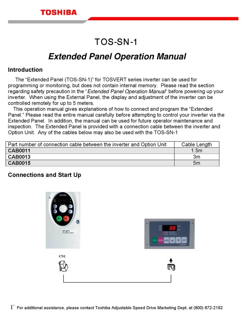
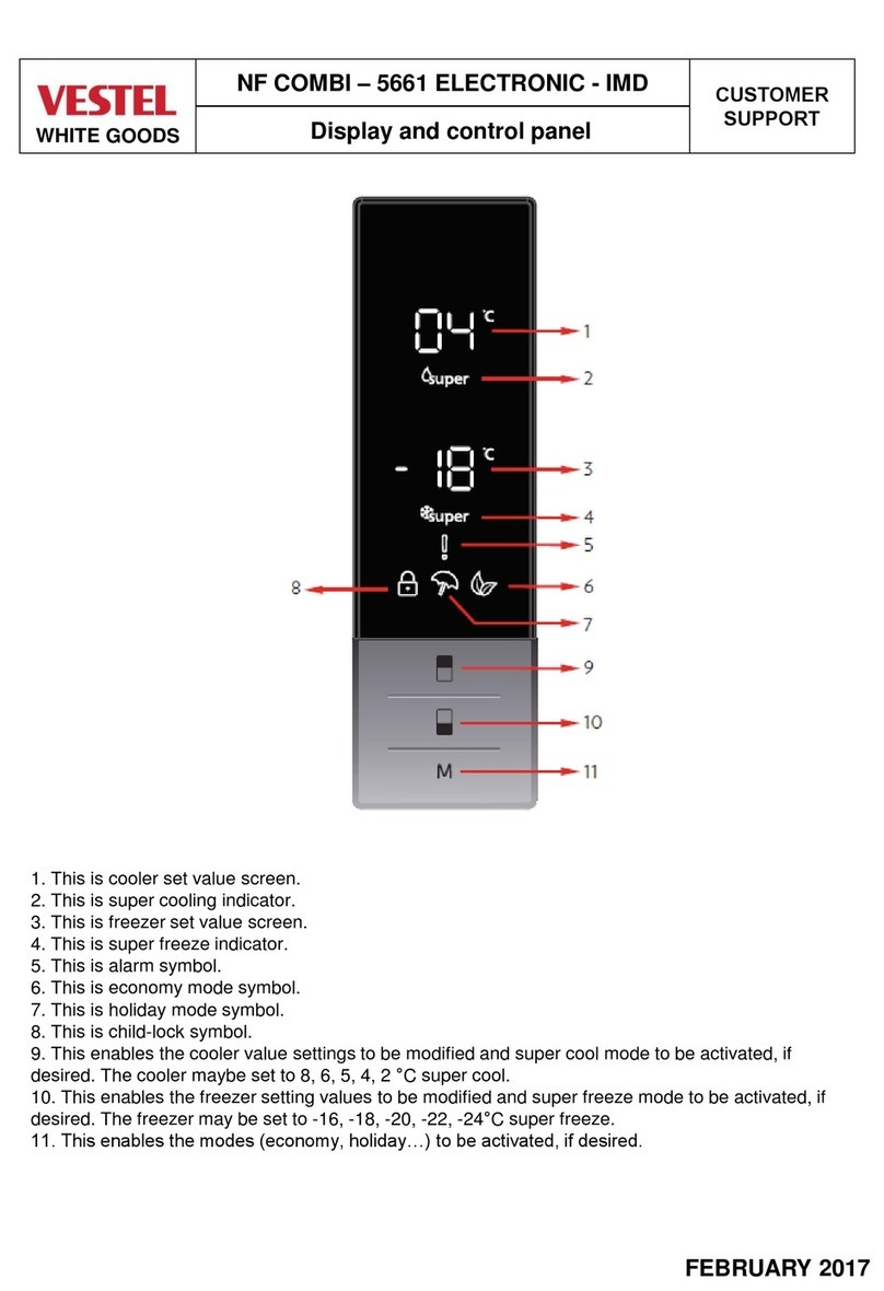
VESTEL NF COMBI 5661 ELECTRONIC IMD Customer support information
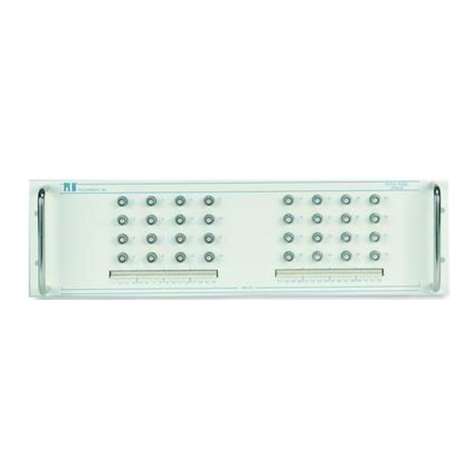
PCB Piezotronics
PCB Piezotronics 070A33 Installation and operating manual
Frigidaire
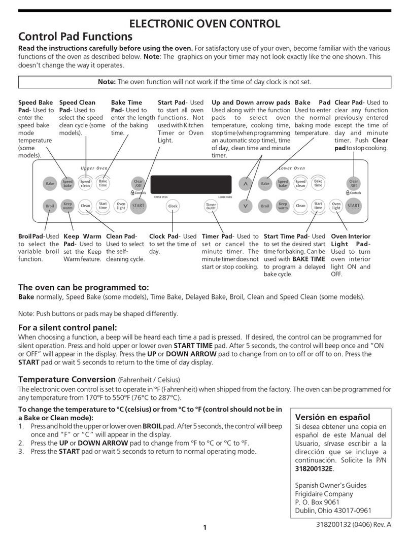
Frigidaire FEB30T7DCB owner's guide
Motorline professional
Motorline professional MPXR92MSWBE User& installer's manual

3i
3i Dualnet-6 instruction manual
Nordelettronica
Nordelettronica NE273-D instruction manual
