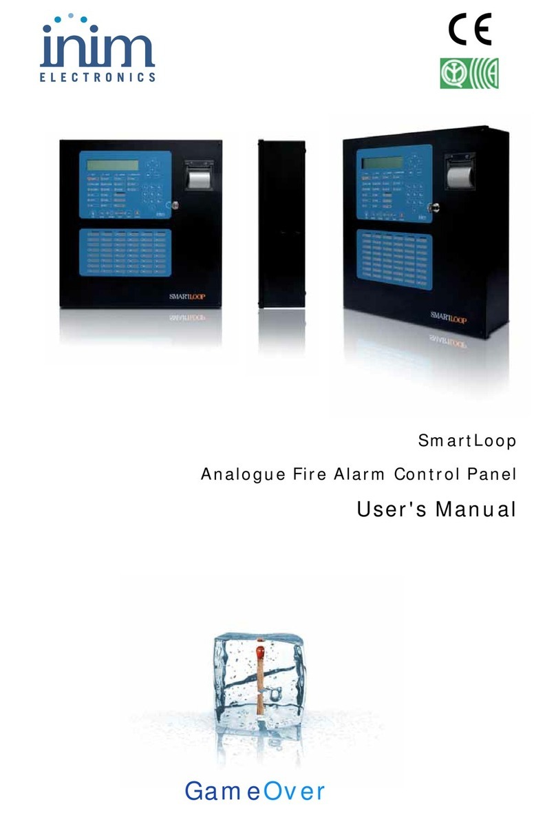
INIM Electronics SmartLoop User manual

SmartLoop
Analogue Fire Alarm Control Panel
Installation manual
GameOver

Installation Manual
2
Copyright
The information contained in this document is the sole property of Inim Electronics s.r.l. No
part may be copied without written authorization from Inim Electronics s.r.l.
All rights reserved.
This Control panel has been designed and developed to the
highest standards of quality and performance implemented by
Inim Electronics.
This control panel must be installed in accordance with the
instructions described in this manual and in compliance with
the laws in force.
All control panels from the SmartLoop series are EN54-2;
EN54-4 compliant.
All control panels from the SmartLoop series, and all
accessory items and special functions have IMQ Sistemi di
Sicurezza certification, unless otherwise stated.

Installation Manual
3
Table of contents
Chapter 1 Overview ............................................................................ 5
1.1 Application and use 5
1.2 In order to validate the IMQ-SISTEMI DI SICUREZZA certification, and in
compliance with EN54-2 regulations, 7
1.3 About the SmartLoop fire alarm panel series 7
1.4 Description of the models 7
1.5 Features 8
Chapter 2 General information.............................................................. 9
2.1 Documentation supplied 9
2.2 Manual details 9
2.3 About the Software 9
2.4 Addressees 9
2.5 Operator authorization—access levels 9
2.6 Intellectual property rights 10
2.7 Disclaimer 10
2.8 Recommendations 10
2.9 Testing the system 10
2.10 Note to the installer 10
2.11 Technical support 10
2.12 Conventions 10
2.13 Manufacturer's name and address 11
2.14 Device identifier 12
2.15 Warranty 12
2.16 Safety laws 12
Chapter 3 Device management............................................................14
3.1 Product handling and storage 14
3.2 Environmental conditions 14
3.3 Unpacking the device 14
Chapter 4 Internal devices ..................................................................16
4.1 The motherboard 16
4.2 About attachment boards 17
4.3 The SmartLoop/2L board 18
4.4 The SmartLoop/NET board 19
4.5 The SmartLAN board 21
4.6 The SmartLoop/PSTN board 22
4.7 The SmartLoop/INOUT board 23
4.8 SmartLetUSee/LED module 23
4.9 The SmartLoop/PRN module (for “/P” models only) 24
4.10 The SmartLetUSee/LCD and SmartLetUSee/LED Repeater panels 26
Chapter 5 Technical specifications........................................................27
Chapter 6 Installation.........................................................................29
6.1 Choosing the mounting location 29
6.2 Installation flow, guidelines and testing 29
6.3 Connecting the SmartLoop/LED module 31
6.4 Connecting the SmartLoop/PRN printer module 32
Chapter 7 Connections .......................................................................33
7.1 Note to the Installer regarding wiring and connection compliancy 33
7.2 About the circuitry 33
7.3 Description of the motherboard terminals 34
7.4 Loop Connections 34
7.5 Loop terminals 35
7.6 Connecting devices to the Loop 35
7.7 NAC Outputs (Notification Application Circuit) 36
7.8 PL terminal (for Shutdown signaling) 37

Installation Manual
4
7.9 AUX output 37
7.10 AUX R output 37
7.11 Alarm relay 37
7.12 Fault relay 37
7.13 Connecting Repeater panels to the RS 485 bus 38
7.14 Connecting the SmartLoopNET module 38
7.15 Connecting the SmartLoop/INOUT Board 38
7.16 Connecting to a PC or serial printer 40
7.17 Connecting a SmartLinkLAN board equipped panel to a PC 40
7.18 Connecting a serial printer 40
7.19 Batteries 40
7.20 Connecting the Thermal Probe 41
7.21 Connecting to the Mains power source (Electrical Switchboard) 42
Chapter 8 Powering up the system....................................................... 44
8.1 Testing wiring integrity 44
Chapter 9 Troubleshooting.................................................................. 47
9.1 NAC, Alarm and Fault output trouble 47
9.2 LOOP Fault 47
9.3 Repeater Fault 48
9.4 Battery Fault 48
9.5 SmartLoopNET Fault 49
9.6 NET Link ALARM-A 49
Appendix A Maintenance ......................................................................50
Appendix B Argus devices supported by the control panel ......................... 51
Apollo devices supported by the control panel......................... 55
Appendix C Order Codes....................................................................... 61
Installer’s notes .................................................................................62

Installation Manual
Overview 5
Chapter 1
Overview
Note: The control panels described in this manual have been designed and developed to the highest
standards of quality, reliability and performance. All product components are capable to
application requirements and able to operate in compliance with the related technical
specifications when the temperature external to their casing complies with Category 3k5 of IEC
721-3-3.
Danger: The GAS control function is not EN54-2 compliant, as this feature is not mentioned in
the aforesaid standard.
Danger: In order to validate the IMQ-SISTEMI DI SICUREZZA certification, and in compliance
with EN54-2 regulations, all the manual alarm buttons and fire detectors employed in
the system must be associated with fire detection and alarm functions.
1.1 Application and use
The SmartLoop analogue-addressable fire alarm panel manages up to eight loops. The SmartLoop is
capable of working in a network environment (maximum configuration 30 nodes arranged in a token
ring). The loops accommodate different types of fire-security devices (detectors, input and output
modules, callpoints, fire bells, etc.). The maximum loop wire length is 2000 m.
The SmartLoop also provides supervised outputs which guarantee full control of peripheal device
functions (e.g. fire bells). The panel identifies and signals alarm, pre-alarm, fault, early warning,
bypassed zone, test and monitoring conditions. The system status is indicated on the display and on
the system status LEDs. The SmartLoop panel supports up to 8 Repeater panels (accessory items)
which replicate system data and allow building occupants with Level 2 authorization to silence and
reset the system. The panel can also be connected to a PC or printer.
The self-addressing feature and reduced-complexity point programming allow fast and easy
installation.
Figure 1 - Example configuration: 5 node token-ring network environment (HorNet)
PSTN
network
INTERNET
Up to 30 panels

Installation Manual
6Overview
Caption
[A] Loop
All the peripheral devices of the system must be connected in parallel to the loop circuit (2 pole STP).
The loop is a closed electrical circuit in which a wide variety of alarm devices can be accommodated.
Opening or closing the circuit at any point will generate a fault signal. The loop circuit communication
path starts on the Loop-Out terminals and ends on the Loop-In terminals. The panel controls and
communicates with the loop devices via digital protocol. The loop utilizes the same two poles for the
power supply to the system devices and the two-way communication channel.
The loop accommodates:
1. Detectors: A smoke detector is an active fire protection device that detects smoke or flames and
issues an alarm thereby alerting building occupants to the danger of fire.
Detectors can be:
- Optical smoke detectors which look for the presence of visible by-products of combustion in the
detection chamber (Tyndall effect).
- Optical/Heat detectors which operate as per optical smoke detectors but also sense for increase in
the environment temperature. The combination of both sensing methods (smoke and heat)
provides faster detection and reduces the false alarm rate.
- Heat detectors: sense for an increase in the temperature in the protected environment. There are
two types of heat detector: Fixed temperature — that signal alarm when the temperature exceeds
the predefined threshold; and Rate-of-rise — that as well as monitoring the predefined fixed
temperature also respond to rapid increase in temperature.
- Ionization smoke detectors: feature a harmless radioactive source within a dual detection
chamber. They operate by sensing for a change in electrical conductivity across the detection
chamber.
- CO detectors: sense the levels of carbon monoxide given off by all carbon-based materials in the
smouldering stages of a fire (often combined with heat detection sensor).
2. Input Module: a device which monitors the status of another device (callpoint, detector, etc.)
and sends the respective information to the panel. The Input module allows the loop to
accommodate any type of device.
3. Output Module: provides a supervised ancillary output. The cause of activation of this output
can be defined during the system configuration phase. The output module interfaces all types of
loop devices (bells, signaling devices, fire door magnets, etc.).
4. Callpoint: a clearly labeled fire button with instructions for use in the event of fire. Usually placed
near building entrances/exits. These push-button alarm-trigger devices allow building occupants
to activate system alarms.
5. Sounder/Flasher: audible/visual alarm signaling devices. The cause of activation (alarm, pre-
alarm, early warning, etc.) can be defined during the system configuration phase.
For the list of the devices the loop accommodates, and for details regarding their wiring and operating
principles, refer to Appendix B and Appendix B.
The loop circuit configuration (as required by the local Fire code in force) is a fault-tolerant circuit
which, in the event of short-circuit or loop interruption, allows the panel to continue to communicate
and drive the elements on either side of the interruption.
[B] Isolator
In order to provide a fault-tolerant loop circuit that is Fire code compliant, isolator modules must be
installed in series with the loop circuit. Isolators modules detect short-circuit conditions and
consequently interrupt the loop circuit. If a short-circuit occurs, the two isolators adjacent to the
shorted section will open and split the loop in such way as to allow the panel to drive the elements on
either side of the interruption. No more than 32 detectors/devices should be installed between two
isolator modules.
Note: Many detectors/devices have built-in isolators and therefore do not require isolator modules.
Refer to Appendix B and Appendix B for further details.

Installation Manual
Overview 7
1.2 In order to validate the IMQ-SISTEMI DI SICUREZZA certification, and
in compliance with EN54-2 regulations,
1. All the manual alarm buttons and fire detectors employed in the system must be associated with
fire detection and alarm functions.
2. The functions associated with the programmable LEDs on the control panel frontplate (Keypad/
Display board and LED board), and on SmartLetUSee/LCD and Smart letUSee/LED Repeaters must
be set up in accordance with the colour of the LEDs:
•RED: FIRE ALARM Status
•YELLOW: FAULT, TEST and DISABLED Status
Note: The GAS control function is not EN54-2 compliant, as this feature is not mentioned in the
aforesaid standard.
1.3 About the SmartLoop fire alarm panel series
There are 3 expandable models (expandable to 8 loops by means of 3 SmartLoop/2L expansion
boards). All have 2 loops and common components housed in the same sized cabinet. Each
expandable model has a technically-downsized version (in same-sized cabinet) with 1 loop for reduced
complexity applications.
All models manage the same functions and support a full spectrum of hardwired and wireless devices.
The SmartLoop fire alarm panel series provides the following models:
• SmartLoop1010/P Advanced model with 1 loop
• SmartLoop2080/P Advanced model with 2 loops expandable to 8 loops
• SmartLoop1010/G Keypad and display model with 1 Loop
• SmartLoop2080/G Keypad and display model with 2 loops expandable to 8 loops
• SmartLoop1010/S Flush front (unequipped) model with 1 loop
• SmartLoop2080/S Flush front (unequipped) model with 2 loops expandable to 8 loops
Figure 2 - SmartLoop Series - Advanced, Keypad and display, and Flush Front
1.4 Description of the models
The “/P” model is equipped with a keypad, display, fault LEDs, fast buttons and a Zone status LED
pad. This model is suitable for locations where extended visual signals and manual control are
necessary. This model can be enhanced with the SmartLoop/PRN thermal printer (accessory item).
SmartLoop1010/P
SmartLoop2080/P
SmartLoop1010/G
SmartLoop2080/G
SmartLoop1010/S
SmartLoop2080/S

Installation Manual
8Overview
The “/G” model is equipped with a keypad, display, fault LEDs and fast buttons and is suitable for
installation in locations where visual signals and manual control are necessary. This model can be
upgraded at any time after installation (for example, if moved to a location where extended visual
signals and manual control are necessary) by replacing its door with a “/P” model door that is
enhanced with a Zone status LED pad and thermal printer option.
The “/S” model has an unequipped door (no keypad, display or LEDs), and is suitable for installation
in locations where visual indications and manual control are not required (e.g. basements). This
model can be upgraded at any time after installation (for example, if moved to a location where visual
signals and manual control are necessary) by replacing its door with a /P model door or /G model door
(refer to respective paragraph for ‘on-door’ equipment details).
1.5 Features
- Manages up to 240 zones
- Network environment capable (maximum configuration 30 panels)
- Group and Zone sharing among panels in the network environment
- Switching power supply 27.6 V @ 4 A with battery charger function
- 2 on-board loops (on expandable 2080 models); 1 on-board loop (on non-expandable 1010
models)
- 3 programmable NAC outputs
- 1 NAC Alarm output
- 1 NAC Fault output
- 1 dry contact Alarm relay
- 1 dry contact Fault relay
- RS485 Bus — accommodates up to 8 SmartLetUSee Repeaters
- 1 power supply output @ 24 V for external devices.
- 1 power supply output @ 24 V for external devices with "power Cutoff" during reset.
- RS232 and USB connectors for uploading/downloading programming data
- 2000 event buffer
The motherboard provides locations for:
- 3 SmartLoop/2L loop expansion boards with 2 loops per board (for 2080 expandable models only)
- 1 SmartLoop/NET network board
- 1 SmartLAN board
- 1 SmartLoop/PSTN board
- 1 SmartLoop/INOUT Input/Output expansion board
- 1 SmartLoop/LED zone-status LED module (for “/P” models only)
- 1 SmartLoop/PRN thermal printer module (for “/P” models only)
Note: The 1010 non-expandable models with 1-loop have exactly the same features and components as
the 2080 expandable models with 2-loops.

Installation Manual
General information 9
Chapter 2
General information
2.1 Documentation supplied
• Installation manual (this manual)
• Programming Manual
• User's Manual
The manuals are supplied with the device. For further copies of the Installation Manual, please contact
INIM ELECTRONICS offices quoting the order number shown in Appendix C .
2.2 Manual details
Title: SmartLoop Installation Manual
• Edition, Issue: 1.01
• Month and Year of printing: April 2007
• Installation Manual Code: DCMIINE0SLOOP
2.3 About the Software
• SmartLeague software version: 2.0.x
• SmartLoop Firmware Version: FWINI0SL0PAA00 1.00
• SmartLoop Loop Driver Firmware Version: FW0000LOOPDRV 1.00
• SmartLoop Frontplate Firmware Version: FW0000SLEDKBD 1.00
• SmartLAN Firmware Version: FWIN00SLAN 1.00
• SmartLoop/PSTN Firmware Version: FW0000SLPSTN 1.00
• SmartLoop/INOUTFirmware Version: FW0000SLIO 1.00
• SmartLetUSee/LCD Repeater Firmware Version: FW0000SLEDKBD 1.00
• SmartLetUSee/LED Repeater LED Expansion Firmware Version: FW0000SLLED 1.00
2.4 Addressees
• Installer
• Technical assistance
2.5 Operator authorization—access levels
Level 1
All building occupants can view the system status (active events) and events log and silence the panel
beeper.
Level 2
ONLY authorized keyswitch users and PIN users (5 digit codes) can Enable/Disable loop devices, bell
outputs, software zones and network devices, and SILENCE or RESET the system.
Level 3
ONLY authorized technicians, appointed by the Installer company can, by means of a screw driver,
remove the screws and open the fire control panel cabinet to insert the J2 Jumper and then, after
entering a 5 digit PIN (5 digit code) access the parameter programming phase and/or carry out
maintenance work (for example, change the battery, replace fuses, etc.).

Installation Manual
10 General information
Level 4
ONLY authorized technicians, appointed by the Manufacturer can, by means of special tools, carry out
repair work on the motherboard (for example, repair or replace SM components).
2.6 Intellectual property rights
The information contained in this document is private property. All rights reserved.
No part of this document may be copied or reproduced unless expressly authorized in writing by INIM
Electronics, in particular the parts regarding the device specified in paragraph 2.14 Device identifier.
2.7 Disclaimer
INIM Electronics s.r.l. shall not be responsible for damage arising from improper application or use.
This control panel should be handled by qualified personnel only. Installation must be carried out
strictly in accordance with the instructions described in this manual, and in compliance with the local
fire code in force.
2.8 Recommendations
INIM Electronics recommends that the entire system be tested on a regular basis (refer to paragraph
2.9 Testing the system).
2.9 Testing the system
This system has been designed to the highest standards of quality and performance. The system may
fail to function as intended due to the failure of a component. Most problems that prevent a fire
control system from operating as intended can be found by regular testing and maintenance (refer to
Appendix A - Maintenance).
Testing should include all detectors, signaling devices and any other operational devices that are part
of the system.
2.10 Note to the installer
In order to provide adequate protection and instructions for proper use, you (the installer) must be
familiar with the operating procedure of this device. As the only individual in contact with system
users, it is your responsibility to instruct them on how to use this system properly and to bring to their
attention that every fire is different in the amount of smoke and rate of burning. Therefore, smoke
and heat detectors may not provide timely warning of fires caused by violent explosions, escaping gas
or improper storage of inflammable materials.
Regardless of its capabilities, a fire alarm system is not a substitute for the necessary precautions
building occupants must take to prevent or minimize the harmful effects of fire.
2.11 Technical support
Our professional engineers are readily available to assist you. Call our phone number and you will be
connected right away to a person who will answer all your questions and provide you with full
technical support.
2.12 Conventions
2.12.1 Glossary and terminology
Panel; device; system: refer to the devices defined in 2.14 Device identifier.
Left, right, behind, above, below: refer to the directions as seen by the operator in front of the
mounted device.
Communicator (telephone, SMS, digital): synonym of dialer.
STP: Shielded twisted pair cable.
Qualified personnel: those persons whose training, expertise and knowledge of the laws and bylaws
regarding service conditions and the prevention of accidents, are able to identify and avoid all possible
situations of danger.

Installation Manual
General information 11
Select: click on and select a specific item (from drop-down menu, options box, graphic object, etc.).
Press: click on a video button, or press a key on the panel keypad.
2.12.2 Graphic conventions
Following are the graphic conventions used in the text.
Note: The detached notes contain important information about the text.
Attention: The attention prompts indicate that total or partial disregard of the procedure could
damage the connected devices.
Danger: The danger warnings indicate that total or partial disregard of the procedure could
injure the operator or persons in the vicinity.
2.13 Manufacturer's name and address
INIM Electronics s.r.l.
Via Ischia Prima, 34
63013 Grottammare (AP) - Italy
Tel: +39 0735 730924
Fax: +39 0735 736134
Conventions Example Description
Text in Italics Refer to paragraph
1.1 Application
and use
Text in italics: indicates the title of a chapter, section, paragraph,
table or figure in this manual or other published reference.
<text> #<CustomerCode> Variable data.
[lowercase
letter]
or [number]
[A] or [1] Representation of a part of the system or video object.
BUTTON CANC, ESC, RESET Computer or control panel keys.

Installation Manual
12 General information
2.14 Device identifier
Figure 3 - Overview
Product category: Fire Alarm Control Panel
Model: SmartLoop
Year of Manufacture: 2007
2.15 Warranty
INIM Electronics s.r.l. warrants the original purchaser that for a period of 24 months from the date of
final acceptance, the product shall be free of defects in materials and workmanship. The warranty
applies only to defects in parts and workmanship relating to normal use. It does not cover:
• Improper use or negligence
• Damage caused by fire, flood, wind or lightning
•Vandalism
• Fair wear and tear
Inim Electronics s.r.l. shall, at its option, repair or replace any defective products. Improper use, that
is, use for purposes other than those mentioned in this manual will void the warranty. For the full
details and conditions regarding the warranty, refer to the purchase order.
2.16 Safety laws
The aim of the instructions in this section is to ensure that the device is installed and handled
properly. This chapter contains vital information. The installer should be familiar with this section and
bring each item to the attention of the system users.
2.16.1 Compliancy
The design and manufacture of the SmartLoop panel comply with EN 54-2 Fire detection and signaling
systems - Control and signaling panels.
The design and manufacture of the power supply comply with EN 54-2 Fire detection and signaling
systems - Power supply devices.
2.16.2 Managing electronic devices
The normal motions of any person may generate electrostatic potential of thousands of volts.
Discharge of this current through semiconductor devices during handling may cause serious damage
which although may not be immediately evident may reduce the reliability of the circuits.
If located in their housings, the electronic circuits of INIM Electronics products are highly immune to
electrostatic discharge.

Installation Manual
General information 13
Do not expose the circuits to damage by removing the modules unnecessarily from their housings.
3. When removing or handling the boards, hold the board edges only.
4. Do not touch the electronic components, the printed circuits or the metal parts of the connectors.
5. Do not hand the module to another person without first ensuring that you both have the same
electrostatic potential. This can be achieved by simply shaking hands.
6. Place the board on an anti-static surface or a conductor surface with the same potential.
Further information regarding procedures relating to safety when working with electronic devices can
be found in Directive IEC 60147-0F.
2.16.3 Setting up the system
In order to provide adequate protection and instructions for proper use, security professionals
(Installers and maintenance technicians) must be familiar with the operating procedure of this device.
Please read the instructions carefully before installing and/or servicing the system.
Before first power-up, be sure that the earth connection has been completed properly on the
respective terminal.
The recommended minimum wire cross section for the earth connection is 2.5 mm2, that is, unless
otherwise stated in accessory documentation.
2.16.4 Replacement and disposal of used devices
Replacement
When replacing used devices, disconnect the devices concerned then complete the connections of the
new devices in compliance with the instructions printed on the respective leaflets.
Contact your local municipal offices for information regarding the disposal of used electronic devices.
Disposal
Do not burn used electronic devices, or allow them to pollute the environment (countryside, rivers,
etc.). Electronic devices must be disposed of in a safe environment-friendly way. In order to avoid
short-circuits, take all the necessary precautions when removing used batteries. Contact your local
municipal offices for information regarding the disposal of batteries.

Installation Manual
14 Device management
Chapter 3
Device management
3.1 Product handling and storage
This device has been properly packed inside a cardboard box, however, care must be taken to avoid
accidental damage during handling. Cartons/boxes should be placed in such a way as to avoid knocks
and falls, and special care must be taken to protect the devices from extreme heat and/or cold.
3.2 Environmental conditions
Temperature limits:
-10° / +55°C for transport and storage
-5° / +40°C operating temperature
3.3 Unpacking the device
Take due care when unpacking the product, and dispose of all waste packaging in accordance with the
local method of disposal.
The cardboard box contains the SmartLoop control panel (cabinet in metal).
Note: All waste packaging must be disposed of in full respect of the local laws in force.
3.3.1 Inside the box
Figure 4 - Box contents
Inside the box you will find
1. Metal cabinet containing the motherboard
2. Installation Manual
3. Plastic bag containing: resistors, + diodes, 2032 lithium battery, keys, battery connection wires

Installation Manual
Device management 15
Attention: The 2032 lithium battery guarantees data retention. You must insert this battery into
its holder (with “+” sign facing you) before connecting the SmartLoopLAN board.
The package does not include:
Thermal probe, batteries (2 x 12 V), programming software CD. These items must be purchased
separately. Be sure you have these items on hand before starting the installation procedure.
Attention: In order to validate the IMQ-SISTEMI DI SICUREZZA certification and comply with EN
54-4 requirements, installation of a thermal probe is essential.
Be sure you have this item on hand before starting the installation procedure.

Installation Manual
16 Internal devices
Chapter 4
Internal devices
4.1 The motherboard
The SmartLoop motherboard has a 32 bit microprocessor that controls all the control panel functions,
and 2 peripheral microprocessors (one per loop) that manage communications with the system
peripherals. INIM’s R & D professionals have developed and designed the SmartLoop motherboard
using ground-breaking new generation fire technologies that ensure maximum precision and
performance. Deployment of the most advanced reflow technology ensures high-noise immunity and
extreme accuracy. Each connection terminal is protected against electrical surges and is high-noise
immune capable. All terminals on the motherboard are clearly marked and easily identifiable (see
Figure below). The motherboard has been especially designed to accommodate with ease the various
SmartLoop attachment boards.
Figure 5 - About the motherboard
4.1.1 The motherboard components
1. Keypad/Display wire to board connector
2. Loop 1 status LEDs (1 green - 2 red)
3. Loop 2 status LEDs (1 green - 2 red)
4. SmartLoop/2L board connector (2-loop expansion board)
5. SmartLAN board connector
6. Microprocessor Hard Reset button
7. Memory jumper (if removed and the panel is switched Off, the system will restore to factory
default settings)
8. Memory battery (3 V lithium battery)
9. COM RS232 connector (DB9 male)
10.USB connector (type B)
11.SmartLoop/PSTN plug-in module connector
12.Clear ground-fault jumper (removal of this jumper clears ground faults)
13.On-panel thermal printer connector

Installation Manual
Internal devices 17
14.Programming jumper (removal of this jumper blocks access to programming)
15.Ancillary power supply connector (not operational with this model)
16.ProbeTH Thermal probe board connector (Thermal probe not included)
17.Switching power-supply module connector
18.SmartLoop/NET plug-in module connector
19.Resettable fuses
20.Connector for external batteries (not operational with this model)
21.Connector for internal batteries (connection wire included)
22.PL terminals (signal battery disconnected conditions) PL closes to GND in the event of shutdown
(primary and secondary power failure) Under normal operating circumstances, PL is open
23.AUX Terminals: 24 V output for external loads
24.AUX-R Terminals: 24 V output for external loads (with "power Cutoff" during reset) Suitable for
powering devices that require power loss in order to reset (e.g.: beam detectors)
25.RS485 Bus for Repeater connections (accommodates up to 8 Repeaters)
26.ALARM relay (dry contact)
27.FAULT relay (dry contact)
28.Supervised FAULT output protected by 1 A fuse
29.SmartLoop/INOUT plug-in module connector
30.Supervised ALARM output protected by resettable 1 A fuse
31.Programmable NAC outputs protected by resettable 1 A fuse
32.Loop 2 In/Out terminals
33.Loop 1 In/Out terminals
4.2 About attachment boards
The motherboards accommodates the following attachment boards:
- Up to 3 SmartLoop/2L loop expansion boards (2 loops per board) - for Expandable models only
(2080)
- 1 SmartLoop/NET Network board - allows to create a control panel network environment (Hornet
technology)
- 1 SmartLAN LAN board for Ethernet connection (Janus Technology)
- 1 Smartloop/PSTN telephone board for PSTN land line connection
- 1 Smartloop/INOUT expansion board (provides 6 Inputs/Outputs)
“/P” models (Advanced models) also support:
- 1 Smartloop/PRN Thermal printer module (fitted to the frontplate) for printout of events in real-
time or on request Refer to the respective paragraphs for the board descriptions.
Figure 6 - The motherboard accessorized with attachment boards

Installation Manual
18 Internal devices
4.3 The SmartLoop/2L board
All the SmartLoop 2080 series (expandable models) have 2 on-board loops expandable to 8 by means
of 3 SmartLoop/2L expansion boards. The models SmartLoop 1010 series (non-expandable) have 1
loop only.
Each loop accommodates up to 240 or 126 (depending on the selected protocol) fire detection/
signaling devices (refer to Appendix B).
Due to electrical incompatibility (refer to Appendix B), different brand devices (i.e. devices using
different protocols) cannot co-exist on the same loop. However, the loops can be programmed
separately thus allowing the system to manage different brand devices on different loops.
Figure 7 - The SmartLoop/2L board
Figure 8 - The SmartLoop/2L board location on the motherboard
4.3.1 The SmartLoop/EXP board components
1. Loop 1 status LED
2. Loop 2 status LED
3. Flat cable SmartLoop/2L board to board connector (up to 3 boards)
4. Flat cable motherboard to SmartLoop/2L board connector
5. Loop 2 In/Out terminals
6. Loop 1 In/Out terminals

Installation Manual
Internal devices 19
7. Board screws (5)
4.4 The SmartLoop/NET board
The SmartLoop/NET board will allow you to create a token-ring network (see “Example configuration:
6 node token-ring network layout”) of up to 30 control panels by means of a 3-pole cable with a
locking ring. The maximum cable length of 2000 meters (allowed between each control panel)
provides a highly fault-tolerant network. Using a supplementary 2-pole cable (5 poles in all), you can
create a protection ring which can pass alarm conditions, coming from a fire control panel with
microprocessor fault, through the ring.
Danger: In order to allow the ring to operate properly, the Port-B and Alarm-B terminals must
be connected to the successive Port-B and Alarm-B terminals.
4.4.1 The SmartLoop/NET board components
1. Aterminals: for the protection-ring connection (to be connected to Alarm-B of the successive
control panel)
2. Communication Port A (to be connected to Port-B of the successive control panel)
3. In-ring LED (indicates the In Service/Out of Service status of the SmartLoop/NET board. If this
LED is Off, the panel is isolated from the HorNet environment.
4. Port A status LEDs (2)
5. Port B status LEDs (2)
6. Bterminals: for the protection-ring connection (to be connected to Alarm-A of the previous control
panel)
7. Communication Port B (to be connected to the Port-A terminals of the previous control panel)
8. Board screws (4)
Figure 9 - The SmartLoop/NET board
8
8
2
1
7
6
8
8
5 4 3

Installation Manual
20 Internal devices
Figure 10 - The SmartLoop/NET board location on the motherboard
Other manuals for SmartLoop
2
Table of contents
Other INIM Electronics Control Panel manuals
INIM Electronics
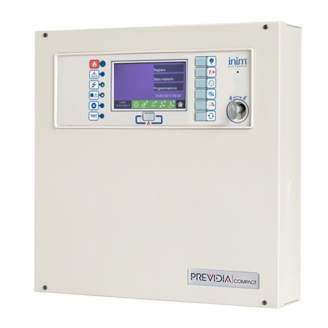
INIM Electronics Previdia Compact User manual
INIM Electronics
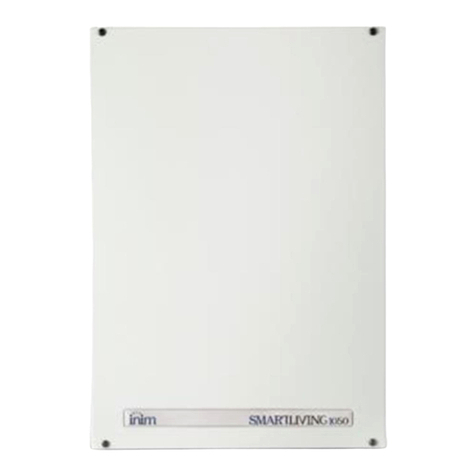
INIM Electronics SmartLiving 505 Assembly instructions
INIM Electronics
INIM Electronics Previdia Compact Quick guide
INIM Electronics
INIM Electronics Prime Series User manual

INIM Electronics
INIM Electronics Prime Series User manual
INIM Electronics
INIM Electronics Prime060S User manual
INIM Electronics
INIM Electronics PREVIDIA MAX Parts list manual

INIM Electronics
INIM Electronics SmartLoop Owner's manual

INIM Electronics
INIM Electronics PREVIDIA MAX User manual
INIM Electronics
INIM Electronics SmartLight User manual
