DGH TECHNOLOGY SCANMATE FLEX User manual
DOCUMENT #: FLEX-INS-OMENG-R4
SCANMATE FLEX
ULTRASOUND PLATFORM
FOR USE WITH SCANMATE v4.2 SOFTWARE
OPERATOR’S MANUAL
0120

2
2TABLE OF CONTENTS
4WARNINGS AND CAUTIONS
5SYMBOL DEFINITIONS
7TERMS AND ABBREVIATIONS
8GENERAL DEVICE DESCRIPTION,
8DEVICE CLASSIFICATION
9INDICATIONS FOR USE
9CONTRAINDICATIONS
9PRESCRIPTION DEVICE STATEMENT
9OPERATOR QUALIFICATIONS
9ALARA STATEMENT
10 SYSTEM COMPONENTS
12 REMOVING THE UBM TRANSDUCER
13 INITIAL SETUP AND ENABLING/DISABLING THE RECHARGEABLE BATTERY
14 SOFTWARE MODES AND SYSTEM MENUS
15 DOCTOR PREFERENCES MENU
17 OPERATOR PREFERENCES MENU
17 SYSTEM PREFERENCES MENU
18 A-SCAN PAGE PREFERENCES
18 B-SCAN PAGE PREFERENCES
19 PATIENT SCREEN
20 B-SCAN/UBM SCREEN
21 USING CLEARSCAN® COVERS WITH B-SCAN PROBES FOR STERILE EXAMINATIONS
21 USING CLEARSCAN® COVERS TO PERFORM UBM OR ANTERIOR SEGMENT EXAMINATIONS
22 PERFORMING B-SCANS
24 PERFORMING UBM SCANS
26 REVIEWING B-SCAN AND UBM VIDEOS
27 B-SCAN AND UBM VOICE CONTROLS
28 A-SCAN SCREEN
29 PERFORMING A-SCANS (CONTACT)
31 PERFORMING A-SCANS (IMMERSION)
33 ALIGNMENT RANKING SYSTEM
33 VIDEO BUFFER FULL
34 REVIEWING A-SCAN VIDEOS AND MEASUREMENTS
35 A-SCAN VOICE CONTROLS
36 IOL CALCULATOR SCREEN
37 PERFORMING IOL CALCULATIONS
38 IOL FORMULA REFERENCES
39 POST REFRACTIVE CALCULATIONS
40 POST REFRACTIVE FORMULAS
42 PERSONALIZED LENS CONSTANTS
44 EXPORTING AND IMPORTING DATA
45 DATABASE MANAGEMENT—SQL SERVER DATABASE BACKUP
45 DATABASE MANAGEMENT—SQLITE DATABASE BACKUP
45 DATABASE MANAGEMENT—RESTORING AND TROUBLESHOOTING

3
46 CLEANING AND DISINFECTION
49 ROUTINE MAINTENANCE—PHYSICAL INSPECTION
50 ROUTINE MAINTENANCE—VERIFYING A-SCAN CALIBRATION
51 REPAIRS AND CUSTOMER SUPPORT
52 ULTRASONIC EMISSIONS INFORMATION
58 ELECTROMAGNETIC IMMUNITY AND EMISSIONS
61 ENVIRONMENTAL CONDITIONS
61 SHELF-LIFE / LIFETIME
61 DISPOSAL
62 TROUBLESHOOTING GUIDE
64 WARRANTY

4
WARNINGS AND CAUTIONS
All warnings and cauons listed throughout this manual are to be observed when operang the
device.
WARNING: Indicates a potenally hazardous situaon which, if not avoided, could cause injury or harm to
the paent or erroneous results.
CAUTION: Indicates a potenally hazardous situaon which, if not avoided, may result in minor injury or
harm to the equipment.
GENERAL WARNINGS
WARNING: EXPLOSION HAZARD. Do not use in the presence of ammable anesthecs, gases, mixtures or in
an oxygen-rich atmosphere.
WARNING: ELECTRICAL SHOCK HAZARD. Do not open the unit. Refer servicing to qualied service
personnel.
WARNING: CONTAMINATION HAZARD. Probes used must be cleaned and disinfected aer each use. Follow
the manufacturer’s instrucons when using disinfectants.
WARNING: BURN HAZARD: The Scanmate Flex does not provide protecve means against burns to the
paent if used with HF surgical equipment. The Scanmate Flex should not be used with HF surgical
equipment.
WARNING: If the Scanmate Flex is used with other devices, current leakage may increase and electric shock
may be caused. It is the user’s responsibility to ensure safety when the probe is to be used with other
devices. If safety cannot be ensured, use of the probe with other devices is not allowed.
WARNING: The device should only be powered using the provided AC adapter. Likewise, the computer
hosng the device should only be powered using a medical grade AC/DC power supply. Use of other
adapters could potenally cause harm to the system, the probe, the operator and/or the paent.
WARNING: Device contains a Lithium Ion baery. Improper service/replacement of the baery may cause
damage to the device, excessive temperatures, re or explosion. The baery is only to be serviced/replaced
by qualied service personnel.
WARNING: Using non-essenal soware in conjuncon with the system could have unknown/adverse
impact on the operaon of the device and is therefore not recommended.
WARNING: Due to the threat of computer viruses, it is recommended that an an-virus program be installed
on the computer running the Scanmate applicaon and that paent records be backed up regularly.
WARNING: Electromagnec interference may cause distoron of received ultrasonic signals. Such
interference may result in distorted images or waveforms.
WARNING: Use of this equipment adjacent to or stacked with other equipment may result in improper
operaon and should be avoided. If such use is necessary, all equipment should be observed to verify normal
operaon.
WARNING: Portable RF communicaons equipment (including peripherals such as antenna cables and
external antennas) should be used no closer than 30 cm (12 inches) to any part of the Scanmate Flex,
including cables specied by the manufacturer. Otherwise, degradaon of the performance of this
equipment could result.
WARNING: Use of accessories, transducers and cables other than those specied or provided by the
manufacturer of this equipment could result in increased electromagnec emissions or decreased
electromagnec immunity of this equipment and result in improper operaon.
WARNING: Probes and cables should not be autoclaved or subjected to intense heat.
GENERAL CAUTIONS
CAUTION: Do not allow sharp objects, such as scalpels or cauterizing knives, to touch the probe or cables.
CAUTION: Disconnect the Scanmate Flex from the host computer before performing roune maintenance or
cleaning. Always follow the manufacturer’s instrucons when cleaning and disinfecng probes.
5
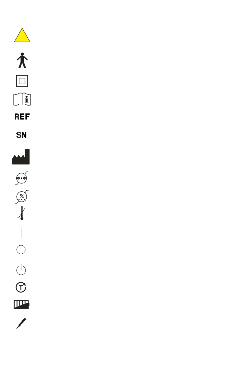
GENERAL WARNING SIGN [2] REF NO. W001
Indicates the need for the user to consult the instrucons for use for important cauonary
informaon such as warnings and precauons that cannot be presented on the medical device
itself.
TYPE B APPLIED PART [3] REF NO. 5840
This symbol indicates the degree of protecon against electric shock. The Scanmate Flex is
classied as Type B Applied Part. This symbol is located on the unit label.
CLASS II EQUIPMENT [3] REF NO. 5172
This symbol indicates that the device is an IEC Protecon Class II (double insulated) device.
CONSULT INSTRUCTIONS FOR USE [1] REF NO. 1641
Indicates the need for the user to consult the instrucons for use.
CATALOGUE NUMBER [1] REF NO. 2493
Indicates the manufacturer's catalogue number so that the medical device can be idened.
SERIAL NUMBER [1] REF NO. 2498
Indicates the manufacturer's serial number so that a specic medical device can be idened.
MANUFACTURER [1] REF NO. 3082
Idenes the device manufacturer. Adjacent to the symbol is the name and address of the
manufacturer.
ATMOSPHERIC PRESSURE LIMITATION [1] REF NO. 2621
Indicates the range of atmospheric pressure to which the medical device can be safely exposed.
HUMIDITY LIMITATION [1] REF NO. 2620
Indicates the range of humidity to which the medical device can be safely exposed.
TEMPERATURE LIMIT [1] REF NO. 0632
Indicates the temperature limits to which the medical device can be safely exposed.
ON (POWER) [3] REF NO 5007
Indicates power on posion for the switch.
OFF (POWER) [1] REF NO 5008
Indicates the power o posion for the switch.
STANDBY [3] REF NO 5009
Indicates the standby status of the device (device powered on).
BATTERY CHECK INDICATOR
Indicates the buon pressed to check the baery charge status of the device.
BATTERY CHARGE INDICATOR
Indicates the amount of baery charge remaining
ACTIVE CHARGING INDICATOR
Indicates that the device is charging the baery.
[1] EN ISO 7000 (5th Ed) Graphical Symbols For Use On Equipment
[2] EN ISO 7010 (2nd Ed) Graphical Symbols—Safety Color and Safety Signs—Registered Safety Signs
[3] IEC 60417:2002 DB Graphical Symbols For Use On Equipment
[4] ISO 15223-1:2012 Medical Devices—Symbols To be Used With Medical Devices Labels, Labeling, And Informaon To Be
Supplied—Part 1: General Requirements
!
SYMBOL DEFINITIONS
yyyy

6
EC REP
USB
Indicates a USB connecon port.
DIRECT CURRENT [3] REF NO. 5031
Indicates the connecon port for the power supply. Adjacent text indicates the input current
voltage and amperage.
WEEE SYMBOL
Indicates that the equipment consists of electronic components and other assemblies that must
not be disposed of as domesc refuse. Refer to the Disposal secon of this manual for more
informaon.
AUTHORIZED REPRESENTATIVE IN THE EUROPEAN COMMUNITY [4] REF NO. 5.1.2
Indicates the Authorized Representave in the European Community. Adjacent to the symbol is
the name and address of the Authorized Representave.
[1] EN ISO 7000 (5th Ed) Graphical Symbols For Use On Equipment
[2] EN ISO 7010 (2nd Ed) Graphical Symbols—Safety Color and Safety Signs—Registered Safety Signs
[3] IEC 60417:2002 DB Graphical Symbols For Use On Equipment
[4] ISO 15223-1:2012 Medical Devices—Symbols To be Used With Medical Devices Labels, Labeling, And Informaon To Be
Supplied—Part 1: General Requirements

7
A-constant The A-constant is a constant provided by an IOL manufacturer to be used in
IOL power calculaons.
ACD Anterior Chamber Depth is dened as the measured distance from anterior
vertex of the cornea and the anterior vertex of the lens.
ACD (constant) The ACD constant is a constant provided by the IOL manufacturer to be
used in Binkhorst formula IOL power calculaons.
a0 The a0 constant is calculated from the manufacturer’s A-constant to be
used in Haigis formula IOL power calculaons.
AXL Axial Length is the distance between the anterior surface of the cornea and
the anterior surface of the rena of the eye.
CLbase curve The contact lens base curve is the known curvature of the plano hard con-
tact lens.
CLover The contact lens over correcon is the measured refracon with the plano
lens in place.
CLpower The contact lens power is the known power of the plano hard contact lens.
IOL Intraocular Lens
IOP Intraocular Pressure
Kcorr The corrected K value that should be used in IOL calculaons for paents
who have previously undergone refracve surgery.
K1 Flat Corneal Axis
K2 Steep Corneal Axis
LT Lens Thickness
nc The keratometer constant.
OD Right Eye (Oculus Dexter)
OS Le Eye (Oculus Sinister)
pACD The pACD constant is calculated from the manufacturer’s A-constant to be
used in Hoer Q formula IOL Power calculaons.
post-Kavg Average of K1 and K2 values measured aer refracve surgery.
pre-Kavg Average of K1 and K2 values measured before refracve surgery.
Rx Refracve error (D)
S.E.post Refracve error measured aer refracve surgery.
S.E.pre Refracve error measured before refracve surgery.
SF The Surgeon Factor constant is calculated from the manufacturer’s A-
constant to be used in Holladay 1 formula IOL Power Calculaons
VCD Vitreous Chamber Depth
TERMS AND ABBREVIATIONS
The following terms and abbreviaons are used within this Operator’s Manual and in the
Scanmate soware.

8
GENERAL DEVICE DESCRIPTION
The Scanmate Flex is a diagnosc ultrasound device used by professionals in the ophthalmic eld
to produce images and measurements of the eye and orbit of adult paents. The system consists
of three main components: an interface module with integrated probe holder, one or more
ultrasonic probes, and the Scanmate soware applicaon.
Three dierent probes are available, at least one of which is required for operaon. The available
probes include an A-scan probe, B-scan probes and a UBM probe. The probe or probes in use are
plugged into the interface module, which is, in turn, connected via a USB cable to a PC running
the Scanmate soware. The minimum PC requirements are as follows:
Minimum Recommended
Processor: 2.0 GHz 3.0+ GHz
Architecture: 32-bit or 64-bit 64-bit
Memory: 2 GB RAM 4 GB RAM
Hard Drive: HDD or SSD SSD
Storage Space: 128 GB 500 GB
Display: 1024 x 768 resoluonA
Peripherals: Mouse/Touchpad, Keyboard
Ports: (2x) USB 2.0B
PC Power Supply: AC/DC Medical Grade TransformerC
Compable OS: Microso Windows 7 (32-bit / 64-bit)
Microso Windows 8.1 (32-bit / 64-bit)
Microso Windows 10 (32-bit / 64-bit)
Microso Windows Server 2008 R2D(64-bit)
Microso Windows Server 2012 / 2012 R2D (64-bit)
Microso Windows Server 2016D(64-bit)
A The soware can be operated using touch controls on systems that have a touch-capable
display. Buons, sliders and combo boxes can be operated by touching the screen. B-Scan/
UBM measurement tools can be operated using touch controls. Zooming and panning of
zoomed B-Scan/UBM images can also be controlled through touch input. Refer to the secons
of this manual detailing B-Scan/UBM control for more informaon.
1 port used for USB interface, 1 port used for footswitch.
WARNING: PCs connected to DGH devices must be isolated from ground using a medical
grade power supply.
D Server Operang Systems only support installaon of the SQL Server database. Refer to
Installaon Guide for more informaon.
Refer to the Scanmate Installaon Manual for informaon on installing and conguring the
soware. The installaon manual also contains informaon on backing up and restoring the
database.
DEVICE CLASSIFICATION
Device: System, Imaging, Pulsed Echo, Ultrasonic
Panel: Radiology
Product Code: IYO
Device Class: II
Regulaon Number: 21 CFR 892.1560
Device: Diagnosc Ultrasonic Transducer
Panel: Radiology
Product Code: ITX
Device Class: II
Regulaon Number: 21 CFR 892.1570
B
C

9
INDICATIONS FOR USE
The Scanmate Flex ultrasound system is a mul-purpose computer-based ultrasonic diagnosc
system for ophthalmic applicaon, intended to both visualize the interior of the eye by means of
ultrasound and to make measurements inside the eye, including the measurement of axial
length for determinaon of IOL Power. The Scanmate Flex is intended for the examinaon of
adult paents.
CONTRAINDICATIONS
None.
PRESCRIPTION DEVICE STATEMENT
CAUTION: Federal law restricts this device to sale by or on the order of a physician.
OPERATOR QUALIFICATIONS
CAUTION: Operators of the device should be trained medical professionals with knowledge
of the use of ultrasonic imaging devices and imaging protocols.
ALARA STATEMENT
The ultrasound energy emied by the Scanmate Flex is of low intensity and will have no adverse
eects on the paent and/or operator. However, the operator is sll cauoned to perform
examinaons using the principle of ALARA (As Low As Reasonably Achievable). All examinaons
should be done so that the paent receives as lile ultrasound radiaon as possible. Do not hold
the probe against the eye or other ssue with the system acvated except when performing an
exam. Do not perform unnecessary exams.
10
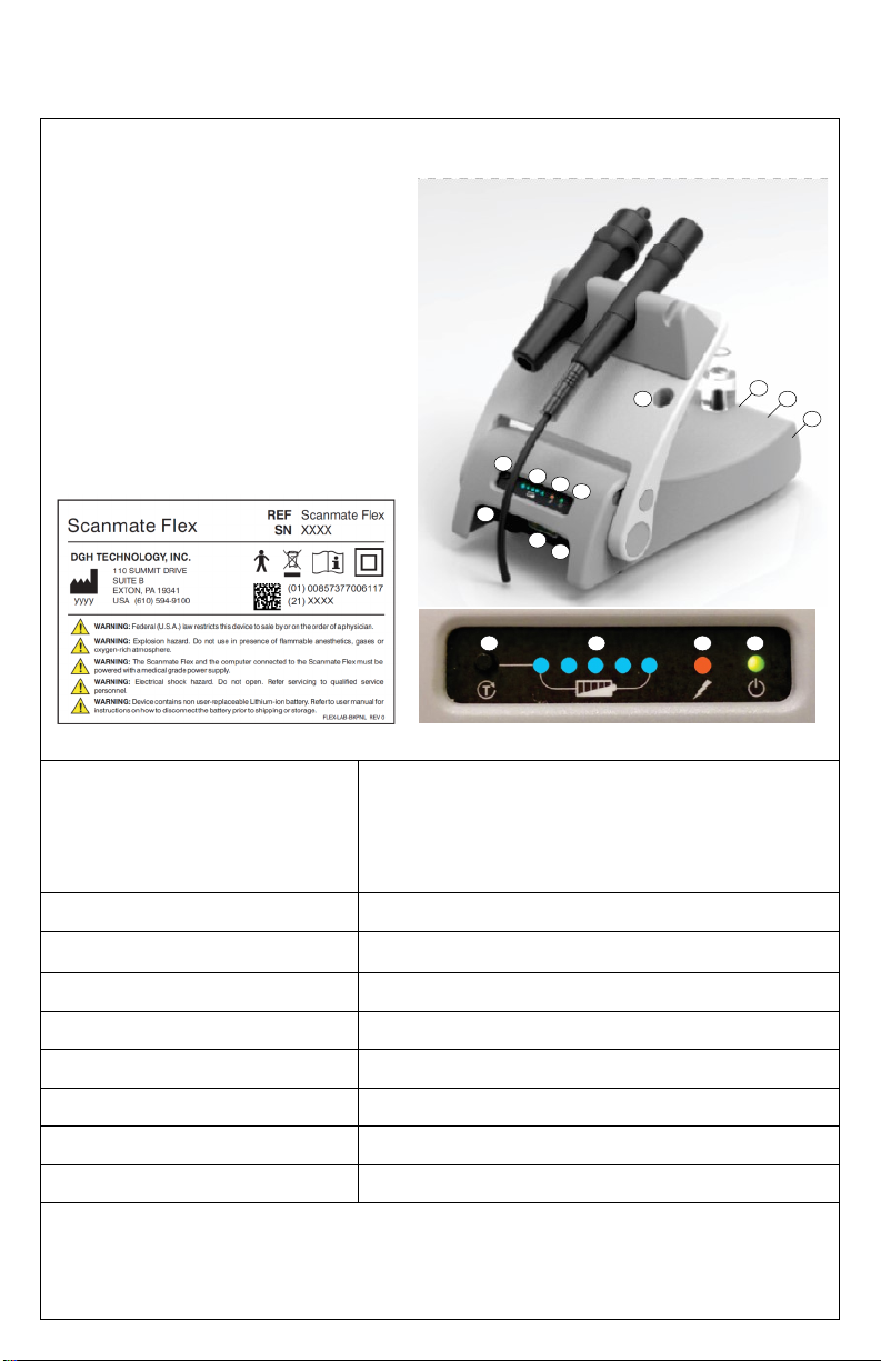
USB INTERFACE MODULE — FLEX-USBIM
1. Baery Charge Check Buon
2. Baery Charge Indicator Lights (blue)
3. Acve Charging Indicator Light (amber)
4. Power On Indicator Light (green)
5. Baery Enable/ Disable Switch
6. B-Scan / UBM connector
7. A-Scan connector
8. A-Scan test block
9. USB Connector
10. Power Switch
11. AC/DC Transformer Connector
Boom Panel Label Front Panel
MAX FRAMES PER SECOND (FPS) 40 fps, 128 sectors, 2-way scan mode
20 fps, 128 vectors, 1-way scan mode
20 fps, 256 vectors, 2-way scan mode
12 fps, 256 vectors, 1-way scan mode
PIXEL COUNT 512 x 512 (4:1 oversampling)
SAMPLING FREQUENCY 80 MHz (max)
PC CONNECTION USB 2.0
BATTERY PACK TYPE* 10.8 V, 3250 mAh Li-Ion
BATTERY LIFE Approximately 4 hours when fully charged.
INPUT VOLTAGE 18 Vdc
INPUT CURRENT 1.67 A
POWER SUPPLY MODEL** EMMAQ180167-P5P-IC (Medical Grade AC/DC Adapter)
* Baery only to be serviced/replaced by DGH Technology, Inc.
** Isolaon from electrical supply mains provided by using the listed medical grade AC/DC adapter.
NOTE: Do not submerge housing. Device housing not sealed against water ingress.
SYSTEM COMPONENTS
The Scanmate Flex is capable of operang various probes. The following tables describe the
Scanmate Flex device and supported probe specicaons.
34
2
1
6
7
8
9
10
11
4321
5

11
B-SCAN PROBES
1. Probe Lens
2. Probe Top Idener
3. Probe Handle
4. Probe Connector
DGH1912 Label DGH1920 Label
MODEL NUMBER DGH1912 DGH1920
TRANSDUCER 12.5 MHz (nominal) 20 MHz (nominal)
SCAN ANGLE DISPLAYED 60 degrees 60 degrees
PROBE POSITION ACCURACY ±3 degrees ±3 degrees
FOCUS 20 mm ±2 mm 21 mm ±3 mm
DEPTH OF FIELD 15 mm—30 mm 15 mm — 30 mm
LATERAL RESOLUTION 0.5 mm ±0.1 mm 0.4 mm ±0.1 mm
AXIAL RESOLUTION <0.35 µS at focal point <0.13 µS at focal point
REPLACEMENT PROBE CABLE FLEX-PCABLE (8’-0” length) FLEX-PCABLE (8’-0” length)
NOTE: Probe may be completely submerged in liquid when disconnected from probe cable.
1
23
4
A-SCAN PROBE— DGH 6006
1. Probe Lens w/ Fixaon LED
2. Immersion Shell Stop
3. Probe Handle
4. Cord Strain Relief
5. Probe cord to cable
DGH 6006 Engraving
TRANSDUCER 10 MHz (nominal)
FOCAL POINT LED brightness adjustable 0% - 100% in soware.
AXL MEASUREMENT RANGE 15.0 mm — 40.0 mm
ACD MEASUREMENT RANGE 2.0 mm — 6.0 mm
LT MEASUREMENT RANGE 2.0 mm — 7.5 mm
AXL MEASUREMENT REPEATABILITY ± 0.03 mm StDev (immersion) , ± 0.10 mm StDev (contact)
AXL MEASUREMENT ACCURACY 100 microns (immersion) , 180 microns (contact)
REPLACEMENT PROBE CABLE N/A. Permanently aached. (6’-0” length)
NOTE: Probe may be submerged up to the edge of the probe cord strain relief.
1
24
3
5

12
REMOVING THE UBM TRANSDUCER
The UBM probe is capable of ulizing both a 35mHz and 50mHz transducer. This transducer can
be changed/replaced by the operator or removed for cleaning. Refer to the Cleaning and
Disinfecon secon for cleaning instrucons.
CAUTION: The gold surface of the transducer is very fragile. Avoid contact with this
surface .
1. Gently pivot the transducer connector to one side.
2. To detach the transducer from the probe, gently grip the sides of the
transducer and unscrew the transducer moving in a counter-
clockwise moon.
3. To reaach the transducer to the probe, gently grip the sides of the
transducer and screw on the transducer moving in a clockwise
moon. When screwing on the transducer, it should be inserted far
enough that the black o-ring is in complete, rm contact.
NOTE: Before reaaching the transducer, be sure that the
connector interior for both the probe and transducer are
completely dry (i.e. aer cleaning). Also, ensure that the
connector interiors are completely dry before storage.
UBM PROBE — DGH1500*
1. Removable Transducer
2. O-Ring
3. Rubber Gasket
4. Probe Top Idener
5. Probe Handle
6. Probe Connector
DGH1500 Label
TRANSDUCER MODEL DGH1500-35 DGH1500-50
TRANSDUCER FREQUENCY* 35 MHz 50 MHz
SCAN ANGLE DISPLAYED 30 degrees 30 degrees
FOCAL POINT 12.8 mm (nominal) 12.8 mm (nominal)
DEPTH OF FIELD 11.5 mm—14 mm 11.5 mm—14 mm
LATERAL RESOLUTION 80 µm (nominal) 50 µm (nominal)
AXIAL RESOLUTION 65 µm (nominal) 50 µm (nominal)
REPLACEMENT PROBE CABLE FLEX-PCABLE (8’-0” length) FLEX-PCABLE (8’-0” length)
REPLACEMENT TRANSDUCER
O-RING
C323000 C323000
* The DGH1500 probe can be used with either the 35 MHz or the 50 MHz transducer.
NOTE: Probe may be completely submerged when disconnected from probe cable.
1
45
6
2
3
13
INITIAL SETUP AND ENABLING/DISABLING THE BATTERY
WARNING: Device contains a Lithium Ion baery. Improper service/replacement of the
baery may cause damage to the device, excessive temperatures, re or explosion. The
Lithium Ion baery is only to be serviced/replaced by qualied service personnel.
WARNING: FIRE HAZARD. Failing to disable the baery prior to shipment could result in
damage to the device, excessive temperatures, re or explosion.
CAUTION: Recharge the baery pack within 10 days of full discharge. Allowing the baery
pack to fully discharge may render it unusable.
CAUTION: If the unit must be stored for an extended period of me, fully charge the
baery before placing into storage. Check the baeries every 6 months and recharge as
needed. Failure to do so may deteriorate the useful life of the baery.
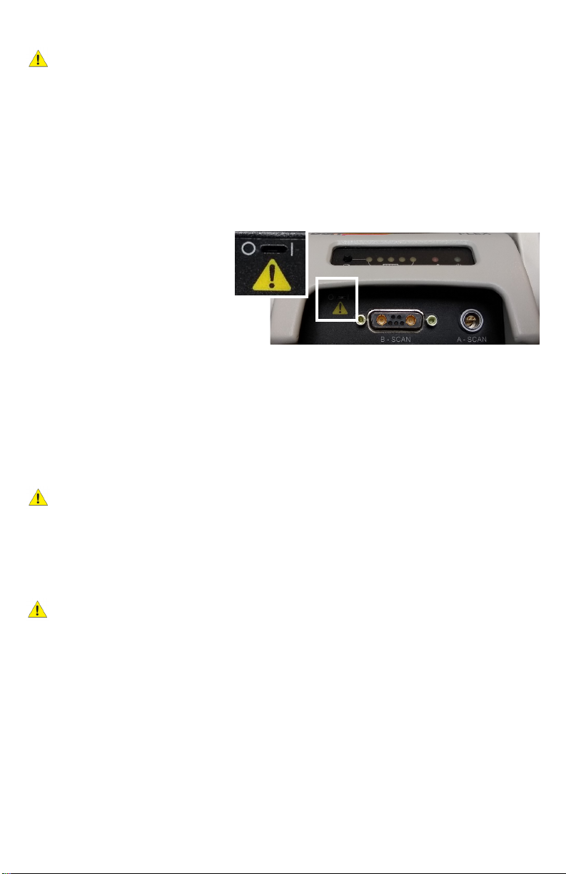
1. Locate the slot in the upper le
corner of the front end‐plate.
Enable the baery by using a
pick to slide the switch to the
| (ON posion). Use only light
force to slide the switch.
NOTE: To disable the baery (i.e. if
being shipped or during extended storage), move this switch to the O (OFF posion).
2. Plug the power cord into its mang connector (labeled “18 VDC 1.6A”). Plug the
transformer into a receptacle and allow the baery pack to charge. The green light on the
front panel will illuminate, indicang the device is powered. The amber light will indicate
acve baery charging. The blue Charge Status lights will become illuminated
indicang the baery charge level.
NOTE: Baery charge can be checked at any me by pressing the Baery Check buon.
CAUTION: Do not aempt to use the device unl it has completed a rst full charge.
Doing so may deteriorate the useful life of the baery.
3. Once charging is complete, connect the other cables and probes. Be aenve to the
alignment of connectors. All connectors on the device have alignment mechanisms to
ensure that cables and probes are properly installed. Do NOT connect the USB cable to the
computer yet.
CAUTION: If it is dicult to connect the probes and/or cables, do not force the connecon.
Verify that alignment between connectors is correct. If proper alignment cannot be
determined, contact DGH Technology, Inc. for customer assistance.
4. Installaon of the Scanmate soware can be performed on mulple computers as needed.
Refer to the Scanmate Installaon Manual for informaon on installing and conguring the
soware.
NOTE: Do not connect the device to the computer unl the Scanmate soware installaon
is complete.
5. Connect the USB cable to the computer and start the Scanmate applicaon. Probe drivers
will be installed the rst me the device is connected. Refer to the Scanmate Installaon
Guide for more informaon.
14
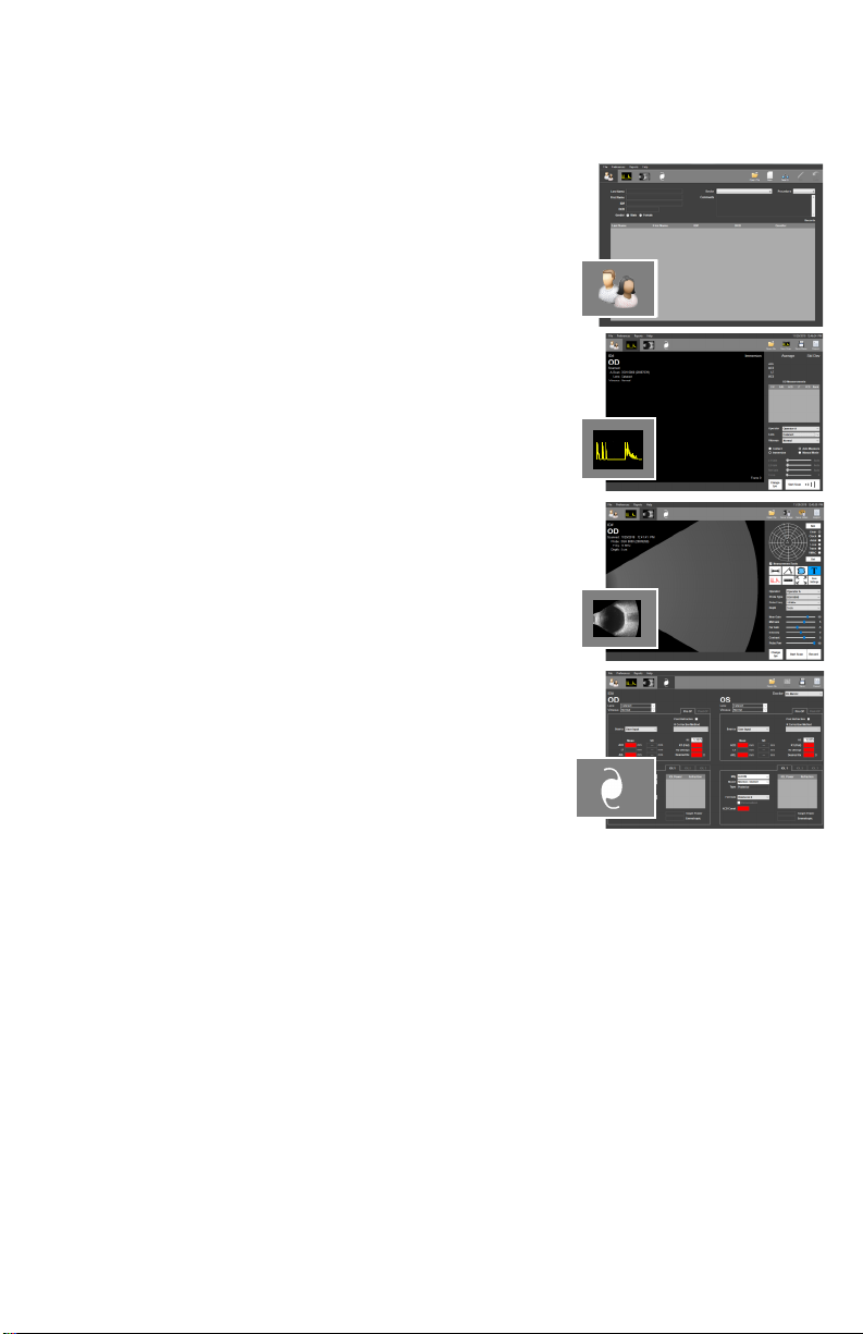
SOFTWARE MODES AND SYSTEM MENUS
The tabs in the upper le-hand corner allow the user to switch between modes of operaon. By
clicking the tabs, the user is able to navigate between the Paent Data, A-Scan, B-Scan/UBM or
IOL Calculaon screens.
PATIENT SCREEN
When starng the program, the Paent Database Screen is
presented. Clicking this tab will bring you to the paent data
screen.
A-SCAN SCREEN
Clicking this tab will bring the operator to the A-Scan screen.
B-SCAN/UBM SCREEN
Clicking this tab will bring you to the B-Scan / UBM screen
IOL CALCULATOR SCREEN
Clicking this tab will bring you to the IOL Calculator.
Addional tools and conguraon opons are available
through the menus which are located above the Mode Tabs.
FILE MENU
The File Menu allows the user to save measurements, images and videos. The File Menu also
allows the user to import and export paent records. The Database Backup / Restore ulity is
accessed through this menu as well.
PREFERENCES MENU
The Preferences Menu allows individual doctor and user proles to be created. Users can
precongure the system according to their preferences and recall the sengs at a later me.
System preferences for system login and report export can be edited from this menu as well.
REPORTS MENU
The Reports Menu allows the user to generate reports from paent records. See the
corresponding secon for informaon on creang A-Scan, B-Scan/UBM and IOL Calculator
reports.
HELP MENU
The Help Menu contains a link to the user manual, soware/system informaon and contact
informaon for DGH Technology, Inc.

15
DOCTOR PREFERENCES MENU
The Doctor Preferences Menu allows the user to create, edit or delete individual doctor
preferences for the device. Doctor Preferences dene the default protocol for performing
A-Scans and IOL Calculaons.
A-SCAN AUTO STOP CRITERIA
This secon allows the user to create standard deviaon thresholds to use with the soware
Auto Stop feature. Individual threshold limits can be dened for the Axial Length (AXL), Anterior
Chamber Depth (ACD) and Lens Thickness (LT). Each category of standard deviaon is calculated
from eight (8) A-Scan measurements. Measurements in the measurement bank must fall within
the standard deviaon thresholds for the system to automacally stop scanning.
MEASUREMENT DELAY
The Measurement Delay is the amount of me aer alignment is detected, but before an A-Scan
measurement is taken. A Measurement Delay of 0 ms will result in a measurement as soon as
alignment is achieved.
ALIGNMENT TIMOUT
Alignment Timeout is the amount of me the probe can be in contact with the eye before the
soware reduces or disables the alignment algorithm. If Alignment Timeout is set to 0 ms, the
alignment algorithm is disabled (Esmate Mode). Refer to the Alignment Ranking System
secon for more informaon on alignment meout.
MIN CASES
This text box allows the user to set the minimum number of procedures that must be performed
before a Personalized Lens Constant is calculated for a given IOL model.

16
IOL 1/IOL 2/IOL 3 TABS
Allow the user to specify up to three preferred IOLs for the currently selected doctor. IOL
informaon is saved in the system using the IOL Conguraon Table.
A-SCAN VELOCITIES TABLE
Click the [A-SCAN VELOCITIES TABLE] buon. The table displayed allows the user to view the
speeds of sound for each lens and vitreous type. These values are used by the soware in
calculaons interpreng A-Scan measurements. This screen also allows the user to enter custom
speeds of sound for custom phakic, aphakic, and pseudophakic lenses.
To use custom speeds of sound to calculate measurements, the custom lens types must be
selected on the A-Scan screen. Customs lens types can be selected from the ‘Lens’ dropdown
box on the right-hand side of the A-Scan screen.
NOTE: Only one (1) set of custom velocies can be stored. Changing these values under one
doctor’s preferences will change them for all users.
IOL CONFIGURATION TABLE
The IOL Conguraon Table allows the user to create, edit, view, or delete IOLs from the
database. Fields are provided to input the IOL manufacturer, model, A-Constant, step range and
type. IOL informaon is specic to the doctor that creates them, so each doctor must enter their
own preferred IOLs.
Once informaon has been entered for the IOL, click the [CALCULATE FROM MFG. A-CONST.]
buon to automacally calculate and display all constants needed for the SRK®-II, SRK®-T,
Hoer® Q, Holladay 1, and Haigis formulas. These values can also be entered manually into the
highlighted elds.
PERSONALIZED LENS CONSTANTS TABLE
The Personalized Lens Constants Table allows the user to manage how Personalized Lens
Constants are calculated. The table displays all Pre-Operave, Post-Operave, paent, and
procedure informaon associated with the currently selected Doctor and IOL. The IOL
informaon table columns can be rearranged by the user. The table rows can be sorted based
upon the selected column.
The Current Personalized Constants secon displays lens constants that are currently being used
for the selected Doctor and IOL. Textboxes within this area are read-only unless the user clicks
the [EDIT] buon. Once edit is selected, the user may manually change any of the current
constant values for the selected Doctor, IOL Manufacturer and IOL Model. If a value outside of
the accepted range for each variable is entered, it will be highlighted in red and must be
corrected before connuing.
The New Personalized Constants secon displays the lens constants as they are calculated by
selecng and deselecng records in the Personalized Lens Constants table.
When the [↑] buon is clicked, the values that are displayed within the New Personalized
Constants secon are loaded into the Current Personalized Constants textboxes.

17
AUTOMATIC CONSTANTS UPDATE
Selecng the [AUTOMATIC CONSTANTS UPDATE] checkbox enables the Automac Constants
Update feature. This feature automacally calculates and updates the personalized lens
constant for the selected doctor and lens based on the records in the table that have “Use
Record” selected. The Personalized Lens Constants are also automacally recalculated when
new records for the specied doctor and IOL manufacturer and model are created and the “Add
to Personalized Lens Table” checkbox on the “Paent Data” Screen is checked. The number of
records used to calculate the constants are also counted and stored automacally upon each
recalculaon. Automacally Calculated Personalized Constants are only available for use once
the number of selected records exceeds the “Min Cases Before Using Personalized Constants”
set in Doctor Preferences.
Min Cases: This value is displayed on the Personalized Constants table. This
indicates the minimum number of cases used in calculang personalized
constants and is not editable on this screen. To edit this value, go to the
Doctor Preferences menu.
Selected Cases: This value is a counter that noes the user how many records have
been selected in the Use Record column. It cannot be edited on this
screen, but will update automacally as records are selected or
deselected for use in personalized constant calculaons.
OPERATOR PREFERENCES MENU
The Operator Preferences Menu allows the user to create, edit or delete individual operators for
the device. Operator preferences such as video playback speeds and auto-saving opons can
also be set in this menu. A eld is provided for user to record notes associated with the
operator. Other sengs that can be adjusted are listed below.
Video Buer Frames: The video buer determines the amount of video that is captured
before recording is stopped or overwrien. Increasing the number
of frames allows the user to record longer videos. This will also
result in larger le sizes.
Bidireconal Scan: If enabled, the B-Scan probe will acquire image informaon
in both sweep direcons.
Average / Interpolate: The soware can be congured to use a frame-to-frame averaging
and/or interpolaon algorithm. Using these algorithms may improve
image quality depending upon the system processor.
.
SYSTEM PREFERENCES MENU
The System Preferences Menu allows the user to set the pracce idencaon informaon, date
format and database login conguraon. Other sengs that can be adjusted are listed below.
Voice Control: Voice control can be enabled/disabled in this menu. Refer To the
B-Scan/UBM Voice Control and A-Scan Voice Control secons for more
informaon.
Default Keratometer The Default Keratometer Index (nc) must be set to match the nc value
Index (nc) the keratometer used. This must be done prior to performing IOL
Calculaons.
18
A-SCAN PAGE PREFERENCES
The A-Scan Page Preferences allow the user to select the Default Lens Type and Default Report.
Default Lens Type: This is the lens type that will be entered by default when a new A-Scan
procedure is started.
Default Report: This seng determines what report will be generated when clicking the
[REPORT] buon on the A-Scan Page.
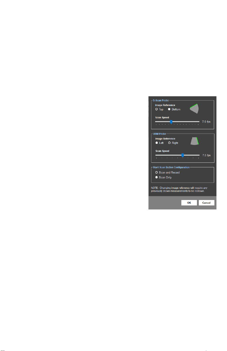
B-SCAN PAGE PREFERENCES
The B-Scan Page Preferences allow the user to adjust image reference, scan speed and scan/
record sengs.
Image Reference: The green line indicates the side of the
image/video that will correspond to the
top posion on the probe.
NOTE: Changing the image reference seng will change the
orientaon of the images stored in the database. If this
reference is changed aer images have been acquired, any
measurements overlaying the image will need to be redrawn.
Scan Speed: Determines the number of frames
that are acquired per second during a
scan.
Start Scan Buon The [START SCAN] and [RECORD]
Conguraon: buons on the B-Scan page can be
congured to operate together or
independently.
- Scan and Record: When the [START SCAN] buon is clicked to start a
scan, the soware will automacally record video. Recording will stop
when the scan is stopped.
- Scan Only: When the [START SCAN] buon is clicked, the scan will
start; however, video will not be recorded unl the [RECORD] buon is
clicked. Recording can be toggled on/o as needed during a scan.
19
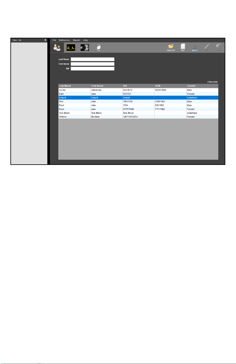
PATIENT SCREEN
The Paent Screen allows the user to search paents and create new or edit exisng records.
The selected paent’s records will be displayed when the A-Scan, B-Scan or IOL tabs are clicked.
Create New Paent: To create a new paent, click the [NEW] icon in the upper right-hand
corner. The elds for entering paent informaon will be highlighted.
Once all informaon is entered, click the [SAVE] icon in the upper right
hand corner.
Search for Paent: To search for an exisng paent, click the [SEARCH] icon in the upper
right hand corner. The search elds will be highlighted. Type in the
idenfying informaon to perform the search. Searches can also be
performed by scrolling through the paent table.
Load Exisng Paent: To view an exisng paent, highlight the desired paent and double
click. The paent informaon will appear in the boxes above.
View Paent Records: Once a paent has been loaded, click the [OPEN FILE] icon in the
upper right-hand corner. A window will appear showing all records
related to this paent. Double click the record to load it.
Edit Paent Records: To edit a paent’s records, load the paent and click the [EDIT] icon in
the upper right-hand corner. The editable elds will be highlighted.
Once the informaon is edited, click the [SAVE] icon in the upper right-
hand corner.

20
B-SCAN/UBM SCREEN
The B-Scan/UBM Screen allows the user to perform B-Scan/UBM procedures and review the
loaded paent’s B-Scan/UBM records.
Open File: To view B-Scan/UBM images, videos and records associated with the
current paent, click the [OPEN FILE]† buon in the upper right-hand
corner. Load the desired le from the window by double-clicking the
corresponding icon.
Posion Map: The Posion Map in the upper right-hand corner allows the user to
record the probe orientaon informaon in the image or video. It
can be set before or aer scanning. Click on the map to place an
indicator and then click the [SET] buon.
A-Scan Overlay: Enabling the A-Scan Overlay will superimpose an A-Scan
waveform over the B-Scan image or video. Use a le-click to
place the vector in the desired posion.
Zoom: Double-click the le mouse buon on the video/image or
click the ZOOM icon to zoom in†. Double-clicking will zoom to
the cursor locaon. Clicking the ZOOM icon will zoom to the
video/image center. To zoom in further, double-click the le
mouse buon again or use the mouse scroll wheel to zoom in and out†.
To reset the zoom, click the ZOOM icon.
If the PC has a touch-capable display, zooming
may be performed using “pinch zoom” touch
controls.
To pan a zoomed image, place one nger on the
B-scan image being displayed and move it in the
desired pan direcon.
†This command may be executed through voice control. Refer to the B-Scan and UBM Voice Controls secon.
Zoom In Zoom Out
Table of contents
Other DGH TECHNOLOGY Diagnostic Equipment manuals


