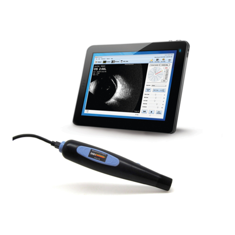
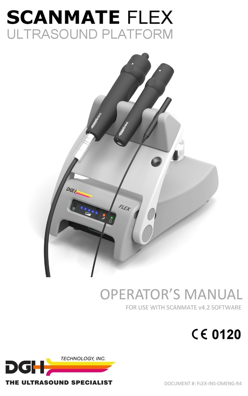
DGH TECHNOLOGY Scanmate A User manual

Page 1 of 89 6000-INS-OMENG Rev. 5
DGH 6000 (SCANMATE-A)
ULTRASONIC A-SCAN
A
Scanmate
DGH 6000
OPERATOR’S MANUAL
For Use with Scanmate Software v4.2
Equipment Manufactured By Authorized Representative
0120
Molenstraat 15
2513 BH, The Hague
The Netherlands
Phone: +31.70.345.8570
EC REP
EMERGO EUROPEDGH TECHNOLOGY, INC.
110 SUMMIT DRIVE
SUITE B
EXTON, PA 19341
USA (610) 594-9100
Molenstraat 15
2513 BH, The Hague
The Netherlands
Phone: +31.70.345.8570
EC REP
EMERGO EUROPEDGH TECHNOLOGY, INC.
110 SUMMIT DR IVE
SUITE B
EXTON, PA 19341
USA (610) 594-9100
Prinsessegracht 20
2514 AP, The Hague
The Netherlands
Molenstraat 15
2513 BH, The H ag ue
The Netherlands
Phone: +31.70.345.8570
EC REP
EMERGO EUROPEDGH TECHNOLOGY, INC.
110 SUMMIT DRIVE
SUITE B
EXTON, PA 19341
USA (610) 594-9100

Page 2 of 89 6000-INS-OMENG Rev. 5
This page intentionally left blank.

Page 3 of 89 6000-INS-OMENG Rev. 5
TABLE OF CONTENTS
1GENERAL DEVICE DESCRIPTION................................................................................6
2DEVICE CLASSIFICATION.............................................................................................7
3INDICATIONS FOR USE..................................................................................................7
4WARNINGS AND CAUTIONS ........................................................................................7
4.1 Meaning of Signal Words................................................................................7
4.2 Device Labels ..................................................................................................8
4.3 Description of Symbols ...................................................................................8
4.4 General Cautions and Warnings......................................................................9
5PRESCRIPTION DEVICE STATEMENT ......................................................................11
6OPERATOR QUALIFICATIONS ...................................................................................11
7USE OF ULTRASOUND IN OPHTHALMIC MEASUREMENTS...............................11
7.1 Introduction to Ultrasound.............................................................................11
7.2 Using Ultrasonic Signals to Ascertain Correct Probe Alignment.................12
7.3 Ultrasonic Measurement................................................................................14
8ULTRASONIC EXPOSURE AND INTENSITIES.........................................................16
8.1 Tissue Exposure to Ultrasound Energy .........................................................16
8.2 Ultrasonic Intensities .....................................................................................16
9BIOMETRIC MEASUREMENT CAPABILITIES..........................................................17
10 INSTALLATION AND CONFIGURATION OF SCANMATE SOFTWARE...............17
11 STARTING THE SCANMATE SOFTWARE.................................................................17
11.1 Launching the Application.............................................................................17
11.2 Splash Screen.................................................................................................17
11.3 Login Screen..................................................................................................18
11.4 No USB Devices Detected Warning..............................................................18
11.5 Touch Controls ..............................................................................................18
12 CONFIGURING THE SCANMATE SOFTWARE.........................................................19
12.1 System Preferences........................................................................................19
12.2 Operator Preferences......................................................................................21
12.3 A-Scan Page Preferences...............................................................................23
12.4 Doctor Preferences.........................................................................................23
12.5 Configuring Custom Velocities.....................................................................26
12.6 Adding IOLs to the Database.........................................................................27
12.7 Personalizing Lens Constants........................................................................29
12.7.1 Overview...............................................................................................30
12.7.2 Procedure..............................................................................................31
13 THE PATIENT DATA SCREEN.....................................................................................34
13.1 Patient Data Screen Controls.........................................................................34
13.2 Entering a New Patient ..................................................................................35
13.3 Searching for a Patient...................................................................................36
13.4 Editing a Patient Record ................................................................................ 36
13.5 Creating a New Procedure.............................................................................37
13.6 Entering Pre-Operative Data..........................................................................37
13.7 Entering Post-Operative Data........................................................................37
14 THE A-SCAN SCREEN...................................................................................................39
14.1 Selecting the Operator ...................................................................................39

Page 4 of 89 6000-INS-OMENG Rev. 5
14.2 Selecting the Lens and Vitreous Type...........................................................39
14.3 Selecting OD or OS .......................................................................................40
14.4 Measurement Modes......................................................................................40
14.5 Automatic Measurement Mode .....................................................................40
14.6 Manual Measurement Mode..........................................................................41
14.7 Selecting Immersion or Contact Measurement Modes..................................43
14.8 Setting the Corneal Compression Lockout Sensitivity..................................43
14.9 Performing a Contact Measurement ..............................................................44
14.10 Performing an Immersion Measurement .......................................................49
14.11 Saving a Measurement File............................................................................54
14.12 Saving a Video Buffer ...................................................................................54
14.13 Reviewing Measurements and Videos...........................................................54
14.14 Voice Controls...............................................................................................55
15 THE B-SCAN SCREEN...................................................................................................56
16 THE IOL CALCULATOR SCREEN (OPTIONAL FEATURE).....................................57
16.1 IOL Calculator Screen Controls ....................................................................58
16.2 Patient Information ........................................................................................58
16.3 Selecting the Doctor.......................................................................................58
16.4 Eye Selection .................................................................................................58
16.5 Post Refractive Selection...............................................................................59
16.6 Measurement Source.....................................................................................59
16.7 Corneal Refractive Index...............................................................................59
16.8 Corneal Power (K1 and K2) ..........................................................................60
16.9 Desired Refraction.........................................................................................60
16.10 Selecting IOLs ...............................................................................................60
16.11 Selecting IOL Power Calculation Formulas..................................................60
16.12 Selecting Personalized Lens Constants.......................................................... 61
16.13 K Correction Method Selection.....................................................................61
16.14 IOL Calculator Outputs .................................................................................61
16.15 Saving Pre-Operative Data ............................................................................61
16.16 Post Refractive Calculation Methods ............................................................62
16.17 Using the Post Refractive Calculator.............................................................65
16.18 Performing IOL Calculations.........................................................................66
16.19 Overview of IOL Power Calculation Formulas.............................................68
16.20 Factors Impacting the Accuracy of IOL Power Calculations........................69
16.20.1 Axial Length.........................................................................................69
16.20.2 Corneal Power.......................................................................................69
16.20.3 Postoperative Anterior Chamber Depth................................................70
16.20.4 Surgical Technique ...............................................................................70
16.20.5 Implant Power.......................................................................................70
17 CREATING REPORTS....................................................................................................71
17.1 IOL Calculator Report...................................................................................71
17.2 A-Scan Short Report......................................................................................71
17.3 A-Scan Custom Report..................................................................................71
17.4 AXL Progression Report ...............................................................................71
17.5 Using Reports ................................................................................................72
17.6 Opening Reports ............................................................................................72

Page 5 of 89 6000-INS-OMENG Rev. 5
17.7 Exporting A-Scan PDF Reports.....................................................................72
18 DATABASE MANAGEMENT........................................................................................73
18.1 Importing and Exporting Data.......................................................................73
19 ELECTROMAGNETIC COMPATIBILITY....................................................................74
20 CARE AND MAINTENANCE........................................................................................76
20.1 Care of Transducer.........................................................................................76
20.2 Cleaning and Disinfecting the Transducer Tip..............................................77
20.3 Cleaning and Disinfecting the Immersion Shell............................................79
20.4 Care of USB Interface Module......................................................................80
20.5 Cleaning the USB Interface Module..............................................................80
20.6 Operating Conditions.....................................................................................80
20.7 Verifying A-Scan Calibration........................................................................80
20.8 Storage...........................................................................................................81
20.9 Transportation................................................................................................81
20.10 Disposal .........................................................................................................82
21 TROUBLESHOOTING....................................................................................................82
21.1 Unable to Get a Measurement .......................................................................82
22 WARRANTY....................................................................................................................83
23 LIFETIME / SHELF-LIFE................................................................................................83
24 CUSTOMER SERVICE ...................................................................................................84
APPENDIX A COMPUTER SYSTEM SPECIFICATIONS...............................................85
APPENDIX B SCANMATE-A SPECIFICATIONS ...........................................................86
APPENDIX C REFERENCES .............................................................................................87
APPENDIX D TERMS AND ABBREVIATIONS..............................................................89

Page 6 of 89 6000-INS-OMENG Rev. 5
1General Device Description
The DGH 6000 is a diagnostic ultrasound device used by professionals in the
ophthalmic field to perform axial length (AXL), anterior chamber depth (ACD), and
lens thickness (LT) measurements of the human eye. Measurements are obtained using
ultrasonic pulse echo technology, whereby short bursts of ultrasonic energy are
transmitted and the resulting echoes are captured, amplified, filtered and processed.
The DGH 6000 is comprised of three main components: a detachable 10-MHz
transducer, a USB interface module and the Scanmate software application.
The transducer uses a single element piezoceramic with a starting frequency of 12.5
MHz +/- 1.25 MHz. This ceramic, after it has been damped, runs at a center frequency
of 10.0 MHz nominal. The tip of the transducer has a spherical radius of curvature,
which focuses the acoustic beam at 23.0 mm nominal. It is also equipped with a fixation
LED to facilitate probe alignment.
The USB Interface Module contains the electronics used to pulse the transducer as well
as to measure, filter and amplify the resulting echoes from internal eye structures. The
USB Interface Module is powered and controlled via a USB 2.0 cable, which must be
connected to a PC or laptop computer running the Scanmate software application.
The Scanmate software interprets the digital signals transmitted by the USB Interface
Module and displays a live “Amplitude Scan” which shows the relative magnitude and
distance of the echo spikes received by the transducer. Specific time distances between
the captured echo spikes are then measured and converted into distance information. A
digital signal processing algorithm is used to analyze the waveform, ensuring that the
probe is properly aligned at the time of measurement. The software assists the user in
performing replacement IOL power calculations using established formulas. The user
can save videos or measurement files or create reports to document the results of the
exam.
The captured A-Scan waveforms, associated measurements, and IOL calculations should
be evaluated only by trained medical personnel. The DGH 6000 does not conduct nor
provide any diagnoses, drive therapeutic outputs, or determine or maintain any life
sustaining or life threatening equipment.

Page 7 of 89 6000-INS-OMENG Rev. 5
2Device Classification
Device: System, Imaging, Pulsed Echo, Ultrasonic
Panel: Radiology
Product Code: IYO
Device Class: II
Regulation Number: 21 CFR 892.1560
Device: Diagnostic Ultrasonic Transducer
Panel: Radiology
Product Code: ITX
Device Class: II
Regulation Number: 21 CFR 892.1570
3Indications for Use
The intended use of the DGH 6000 is the measurement of axial length, anterior chamber
depth, and lens thickness of the human eye. The DGH 6000 is also intended to calculate
the optical power of an IOL that is to be implanted during cataract surgery. The DGH
6000 is intended to be used solely by qualified medical professionals. Clinical
consideration and judgment should be applied when using the DGH 6000.
4Warnings and Cautions
4.1 Meaning of Signal Words
In this manual, the signal words “Warning” and “Caution” are used to highlight
important safety and usage instructions. All users of the DGH 6000 must understand the
meanings of these signal words.
Signal Word
Meaning
! WARNING
Indicates a potentially hazardous situation which if not
avoided could cause injury or harm to the equipment or
erroneous results.
! CAUTION
Indicates a potentially hazardous situation which if not
avoided may result in minor injury or harm to the
equipment.

Page 8 of 89 6000-INS-OMENG Rev. 5
4.2 Device Labels
The label shown below is located on the underside of the USB Interface Module.
4.3 Description of Symbols
This symbol indicates the degree of protection against electric shock. The
DGH 6000 Scanmate-A is classified as type BF equipment.
This symbol indicates that the DGH 6000 Scanmate-A is an IEC Protection
Class II (double insulated) device.
This symbol instructs the operator to read the operating manual.
This mark indicates that Notified Body 0120 (SGS United Kingdom Ltd)
has certified the management system of DGH Technology, Inc. meets the
requirements applicable requirements of 21 CFR 1010 (Performance
Standards for Electronic Products: General) and 21 CFR 1050 (Performance
Standards for Sonic, Infrasonic, and Ultrasonic Radiation-Emitting
Products). The device also conforms to the following International
Standards:
▪EN 60601-1: Medical electrical equipment –Part 1: General
requirements for safety –IEC 60601-1
▪EN 60601-1-2: Medical electrical equipment –Part 1: General
requirements for safety. Collateral standard: Electromagnetic
compatibility requirements and tests. IEC 60601-1-2
▪NEMA Standard Publication UD-2: Acoustic Output Measurement
Standard for Diagnostic Ultrasound Equipment
▪NEMA Standard Publication UD-3: Standard for Real-Time Display
of Thermal and Mechanical Acoustic Output Indices on Diagnostic
Ultrasound Equipment
0120

Page 9 of 89 6000-INS-OMENG Rev. 5
This symbol indicates that Emergo Europe is the European Authorized
Representative for this device.
This symbol indicates that DGH Technology, Inc. is the manufacturer of the
DGH 6000 Scanmate-A device. The YYYY under the symbol indicates the
year the device was manufactured.
This symbol indicates that the model number of this device is DGH 6000.
This symbol indicates the serial number of the device. YYYY indicates
the year of manufacture and XXXX indicates the unit number.
This symbol located on the DGH 6000 indicates that the equipment consists
of electronic assemblies and other components that may be subject to
Directives 2002/96/EC, 2003/108/EC, and 2002/95/EC of the European
parliament, which advises that electrical and electronic devices must not be
disposed of as normal domestic refuse. In order to prevent environmental
risks or endangerments by non-professional disposal, the disposal of this
product, including any accessories, must comply with valid practices as
outlined in Directives 2002/96/EC, 2003/108/EC, and 2002/95/EC and local
regulations. All electronic components and systems should be returned to
Original Manufacturer for disposal.
4.4 General Cautions and Warnings
! CAUTION
The probe must be cleaned after each use. Cleaning the probe is an essential step
prior to effective disinfection. Follow the manufacturer’s instructions when using
disinfectants.
! WARNING
Equipment not suitable for use in the presence of flammable mixtures.
! WARNING
Do not allow sharp objects, such as scalpels or cauterizing knives, to touch the
transducer or cables.
EC REP
yyyy
REF
SN

Page 10 of 89 6000-INS-OMENG Rev. 5
! WARNING
If the device is used in conjunction with other devices, current leakage may
increase and electric shock may be caused. It is the user’s responsibility to ensure
safety when the device is to be used in conjunction with other devices. If safety
cannot be ensured, the simultaneous use of devices is not allowed.
! WARNING
The use of a “Non-Medical” grade AC Adapter could potentially cause harm to
the system, the probe, the operator and/or the patient.
! WARNING
Use of this equipment adjacent to or stacked with other equipment may result in
improper operation and should be avoided. If such use is necessary, all equipment
should be observed to verify normal operation.
! WARNING
Electromagnetic interference may cause distortion of received ultrasonic signals.
Such interference may result in distorted waveforms.
! WARNING
Use of accessories and cables other than those specified or provided by the
manufacturer of this equipment could result in increased electromagnetic
emissions or decreased electromagnetic immunity of this equipment and result in
improper operation.

Page 11 of 89 6000-INS-OMENG Rev. 5
5Prescription Device Statement
6Operator Qualifications
This DGH 6000 is intended to be used by trained medical professionals. The medical
professional operating the DGH 6000 must have a general knowledge of the use of
ultrasonic medical devices. Use of the DGH 6000 requires adequate dexterity to
position the probe safely. The DGH 6000 uses audio feedback to inform the operator of
the scan status.
7Use of Ultrasound in Ophthalmic Measurements
7.1 Introduction to Ultrasound
Ultrasound offers a non-invasive method to examine the interior of solid objects.
Ultrasonic pulses consist of sound waves of a frequency level too high to be heard by
the human ear. When a sound impulse strikes an interface, some sound is reflected, and
some sound is transmitted. Because some sound will pass through the surface and be
reflected by the next surface, complex structures can be examined with ultrasound.
When ultrasound penetrates an object with several interfaces, the reflected ultrasound
can be observed on a graphic display as a two-dimensional waveform with peaks that
are related to the positions of the interfaces.
The DGH 6000 transducer emits ultrasound pulses and detects ultrasound signals that
have been reflected back. The time delay between the echoes is used to calculate
distances between surfaces in the eye.
! WARNING
Portable RF communications equipment (including peripherals such as antenna
cables and external antennas) should be used no closer than 30 cm (12 inches) to
any part of the device, including cables specified by the manufacturer. Otherwise,
degradation of the performance of this equipment could result.
! CAUTION
The DGH 6000 is a prescription device and is only to be used by, or under the
supervision of, a licensed physician.

Page 12 of 89 6000-INS-OMENG Rev. 5
Note: Ultrasound cannot travel through air because air is not dense enough for the high
frequency waves to propagate. Ultrasonic measurements must therefore be
performed by direct contact or through a denser medium such as water.
7.2 Using Ultrasonic Signals to Ascertain Correct Probe Alignment
Sound travels in straight lines, so the direction of reflected sound is based solely on its
angle of incidence. Sound hitting an interface perpendicularly will reflect back along the
same path that it approached (Figure 7-A). Sound hitting an interface at an angle will
reflect at an angle away from the source (Figure 7-B). The transmitted sound will
continue on at a lesser amplitude because of reflected energy lost at the interface.
When reflected ultrasound is shown as a two-dimensional waveform, the peaks are
related to the positions of the interfaces. By comparing the relative height (intensity) of
the peaks, one can determine the angle at which the sound is striking it (Figures I-A and
I-B). Steadily diminishing peaks are an indicator that the ultrasound is not perpendicular
to the interfaces.
Using these properties of ultrasound, the alignment of an ultrasound beam through the
eye can be determined. Proper alignment is crucial to the accuracy of measurements that
will be used for IOL calculations. Figure 7-C illustrates an ultrasonic pattern typical
when alignment along the visual axis is met. Please note the two high, clear peaks
representing the anterior lens and posterior lens interfaces, along with a strong peak
representing the retinal interface. Figure 7-D illustrates a pattern representing
misalignment. Incorrect alignment will result in improper measurements.
Figure 7-A Sound hitting an interface
perpendicularly.
Figure 7-B Sound hitting an interface
at an angle.

Page 13 of 89 6000-INS-OMENG Rev. 5
The DGH 6000 Scanmate-A incorporates a pattern recognition program that
automatically checks for proper alignment. It first looks for the proper pattern of
reflectance peaks from each expected interface. Then the software examines the retinal
spike for particular signal characteristics which are produced only by retinal interfaces.
Incorrect signal patterns will not be measured until the alignment is corrected. Audible
feedback will guide the operator to proper alignment.
Figure 7-C Correct alignment along the
visual axis.
Figure 7-D Incorrect alignment along the
visual axis.

Page 14 of 89 6000-INS-OMENG Rev. 5
7.3 Ultrasonic Measurement
The speed of sound increases in denser materials. Liquids or substances containing large
amounts of water conduct ultrasound very well; air does not conduct ultrasound. Figure
7-E shows a list of the established speeds of sound for ophthalmic structures.
Aphakic
Phakic Pseudophakic
Cornea
Aqueous
Lens - Normal
Lens - Cataractous
Vitreous
IOL PMMA
IOL Silicone
1640 m/s
1532 m/s
1640 m/s
1629 m/s
1532 m/s
2760 m/s
1000 m/s
Normal
or
Cataractous Aqueous PMMA
or
Silicone
Aqueous
Cornea
Vitreous
Figure 7-E Speeds of sound for ophthalmic structures.
Using the relationship between the density of a material and the speed of sound,
ophthalmic A-Scans obtain distances in the eye by performing a two-step process. First,
a pulse of sound is timed as it travels through the eye, reflects off the retina, and returns
to the transducer. Second, the lengths are calculated based on the travel time and the
speed of sound through the eye:
distance = velocity ×time
2
Early ophthalmic ultrasonic units used an average speed of sound of 1550 m/s for phakic
eyes and 1532 m/s for aphakic eyes. The DGH 6000 Scanmate-A lets the user select the
type of eye being examined, and will then automatically use the proper speed for each
part of the eye. Using specific velocities for each part of the eye increases the accuracy
of measurements. Ex:
lens thickness (normal) = 1641 m/s × time (s)
2
Cornea thickness in all eye types is assumed to be 550 m, with a velocity of 1641 m/s.
This assumption is part of the ACD calculation. Anterior Chamber Depth is defined as
the measured distance from anterior vertex of the cornea and the anterior vertex of the
lens.
In pseudophakic eyes, the lens thickness is not measured. A standard thickness is
assumed, depending on the type of implant present. The following table summarizes the
assumed thicknesses and velocities.
Cornea 1641 m/s
Aqueous 1532 m/s
Lens- Normal 1641 m/s
Lens- Cataractous 1629 m/s
Vitreous 1532 m/s
Silicone Oil 980 m/s
IOL PMMA 2780 m/s
IOL Silicone 980 m/s

Page 15 of 89 6000-INS-OMENG Rev. 5
Material
Velocity (m/s)
Thickness (m)
PMMA IOL
2780
700
Silicone IOL
980
1350
Acrylic IOL
2180
800
Note: The velocities table within the Scanmate application displays the preset
velocities and allows the user to specify a custom velocity and thickness to be
used for calculation. Custom velocities are selected as Custom Aphakic, Custom
Phakic, or Custom Pseudophakic lens types.

Page 16 of 89 6000-INS-OMENG Rev. 5
8Ultrasonic Exposure and Intensities
8.1 Tissue Exposure to Ultrasound Energy
The ultrasound energy emitted by the DGH 6000 is low intensity and will have no
adverse effects on the patient and/or operator. However, the operator is still cautioned to
perform examinations using the principle of ALARA (As Low As Reasonably
Achievable). All examinations should be done so that the patient receives as little
ultrasound radiation as possible. Do not hold the probe against the eye or other tissue
with the system activated except when making a measurement. Do not make
unnecessary measurements.
8.2 Ultrasonic Intensities
The DGH 6000 has only one mode, and ultrasonic intensity settings are not under the
control of the operator. Thus, the values below are the values to be expected for a typical
transducer.
Since the DGH 6000 is not capable of exceeding either a TI of 1.0 or an MI of 1.0 in any
operating mode, the output of the system is reported as shown in the Table below.
The appropriate Thermal Index is the Thermal Index for Soft Tissue, TIS, for the non-
scanning case with a beam aperture of less than 1.0 cm.
Output Summary Table
Transducer Model
(used with DGH 6000)
Ispta.3
TI Type
TI Value
MI
Ipa.3 @ MImax
DGH6006
0.469 mW/cm2
TIS non-scan,
Aaprt < 1.0
0.0004
0.131
3.49 W/cm2
The acoustic output values given above are based on a presumed attenuation of
ultrasound on tissue, as developed by the U.S. Food and Drug Administration in 1985,
and later incorporated into other international standards.
The attenuated intensity in the eye at the transducer focus (corresponding to maximum
intensity) may be calculated according to the formula recommended by the FDA:
where Itis the estimated in situ intensity, Iwis the measured intensity in water at the
focus of the transducer, fis the ultrasonic frequency, and zis the distance from the face
of the probe to the transducer focus, which is the point of measurement (23 millimeters).
The nominal piezoceramic (crystal) frequency of these transducers is 10 MHz. The
actual frequency of a particular transducer may vary from this value. The tissue
calculations above were done with the measured frequency of the transducer used for the
tests.
( )
zf
wt eII −
= 069.0

Page 17 of 89 6000-INS-OMENG Rev. 5
9Biometric Measurement Capabilities
The following table shows the measurement range and capabilities for the DGH 6000
(Scanmate A).
Parameter
Range
Accuracy
Resolution
Axial length
Anterior chamber depth
Lens thickness
15 mm to 40 mm
2.0 mm to 6.0 mm
2.0 mm to 7.5 mm
+/- 0.1mm
+/- 0.1 mm
+/- 0.1 mm
0.01 mm
0.01 mm
0.01 mm
10 Installation and Configuration of Scanmate Software
Refer to the Scanmate Installation Manual for information on installing and configuring
the software.
11 Starting the Scanmate Software
11.1 Launching the Application
Once installed, the “Scanmate” shortcut appears on the Windows desktop
and in the start menu. Click on the desktop icon to start the DGH
Scanmate application.
11.2 Splash Screen
The Scanmate splash screen will appear while the application loads.

Page 18 of 89 6000-INS-OMENG Rev. 5
11.3 Login Screen
A single username and password is used to
gain access to the software and database for
all users. By default, the Scanmate software
is set to automatically log in when the
application is started using the username
and password specified in System
Preferences. To change this setting,
uncheck the “Automatic Login” preference
in the System Preferences menu. If a login
is requested, enter the username and
password created during software
installation.
11.4 No USB Devices Detected Warning
If the USB Interface Module is not attached,
a warning box will appear.
Clicking “OK” will complete the log-in and allow the Scanmate software to be used
without the USB Interface Module. Although no scans can be completed, the software
can still be used to perform IOL calculations or view completed reports, saved
measurements and saved videos.
If the Scanmate software is being used without the USB Interface Module attached, the
software will require probe key authentication before using, and after every 20 hours of
use. Warnings will appear every hour after 15 hours of use. To provide authentication,
plug a USB Interface Module into a USB port; authentication will complete in a few
seconds.
11.5 Touch Controls
The Scanmate software can be operated using touch controls on systems that have a
touch-capable display. Buttons, sliders and combo boxes can be operated by touching
the screen.

Page 19 of 89 6000-INS-OMENG Rev. 5
12 Configuring the Scanmate Software
12.1 System Preferences
The “System Preferences” window provides controls to set various configuration items
for the system. The System Preferences window can be accessed by selecting
Preferences →System from the Menu Bar.
The Practice Name, Practice Address Line 1, Practice Address Line 2 and Practice
Phone Number textboxes allow the user to enter practice information that will appear
on reports generated by the software.
The Date Format textbox allows the user to select either MM/dd/yyyy or dd/MM/yyyy
date format for the software.
The Automatic Login checkbox allows the user to select if login is required upon
system startup or if the user is automatically logged in. By default, this checkbox is
enabled, indicating that the username and password will be entered automatically.
The Default Keratometer Index (nc)box is provided to give the user the ability to
configure the default index of refraction used on the IOL Calculator screen.

Page 20 of 89 6000-INS-OMENG Rev. 5
The default nc should be set before K1 and K2 are entered for a patient. The nc
associated with each set of corneal power measurements can be reviewed or adjusted on
the IOL Calculator Screen. Failure to adjust the default nc to match the nc of the
keratometer used to measure corneal power can result in errors in the IOL Calculation.
See Section 16.20 of this guide for more details.
The Report PDF Export Location setting allows the user to specify the default
directory where pdf reports will be exported. The default directory can be any local or
mapped network drive.
The Enable Voice Control checkbox allows the user to enable or disable voice control.
If voice control is enabled, the user can select how to initiate voice commands from the
textbox below. Voice commands may be configured to be initiated by pressing the Enter
key or by a verbal command of “Hey Flex”. Voice control sensitivity can be adjusted in
this menu as well.
The Database Type textbox lists the database type currently being used by the
Scanmate software. For more information on database types, refer to the Scanmate
Installation Guide.
The Database Location textbox specifies the location of the DGH Database Server
hosting the DGH-Scanmate database. To change the Database Location for the DGH
Scanmate application, select the “Change Configuration” button and follow the prompts.
For more information on configuration of the software, refer to the Scanmate Installation
Guide.
The Database Name textbox displays the name of the DGH-Scanmate database. The
default database name is created automatically when installing the system and is not user
configurable.
The Username textbox displays the username that the Scanmate application uses to
connect to the database. To change the Username for the DGH Scanmate application,
select the “Change Configuration” button and follow the prompts. For more information
on configuration of the software, refer to the Scanmate Installation Guide.
The Password textbox displays the password that the Scanmate application uses to
connect to the database. To change the Hint that the DGH Scanmate application
displays, select the “Change Configuration” button and follow the prompts. For more
information on configuration of the software, refer to the Scanmate Installation Guide.
! WARNING
To avoid IOL power calculation errors, it is important that the corneal refractive index
(nc) of the keratometer used to calculate corneal power matches the default refractive
index (nc) set in System Preferences for the DGH Scanmate.
This manual suits for next models
1
Table of contents
Other DGH TECHNOLOGY Diagnostic Equipment manuals
