DGH TECHNOLOGY Scanmate-B DGH 8000 User manual

Page 1 of 53 8000-INS-UMENG Rev. 4
DGH 8000 (SCANMATE-B)
ULTRASONIC B-SCAN
B
Scanmate
DGH 8000
OPERATOR’S MANUAL
For Use with Scanmate Software v4.2
Equipment Manufactured By Authorized Representative
0120
Molenstraat 15
2513 BH, The Hague
The Netherlands
Phone: +31.70.345.8570
EC REP
EMERGO EUROPEDGH TECHNOLOGY, INC.
110 SUMMIT DRIVE
SUITE B
EXTON, PA 19341
USA (610) 594-9100
Molenstraat 15
2513 BH, The Hague
The Netherlands
Phone: +31.70.345.8570
EC REP
EMERGO EUROPEDGH TECHNOLOGY, INC.
110 SUMMIT DRIVE
SUITE B
EXTON, PA 19341
USA (610) 594-9100
Prinsessegracht 20
2514 AP, The Hague
The Netherlands
Molenstraat 15
2513 BH, The Hague
The Netherlands
Phone: +31.70.345.8570
EC REP
EMERGO EUROPEDGH TECHNOLOGY, INC.
110 SUMMIT DRIVE
SUITE B
EXTON, PA 19341
USA (610) 594-9100

Page 2 of 53 8000-INS-UMENG Rev. 4
This page intentionally left blank.

Page 3 of 53 8000-INS-UMENG Rev. 4
TABLE OF CONTENTS
1GENERAL DEVICE DESCRIPTION................................................................................5
2DEVICE CLASSIFICATION.............................................................................................5
3INDICATIONS FOR USE..................................................................................................5
4WARNINGS AND CAUTIONS ........................................................................................6
4.1 Meaning of Signal Words...............................................................................6
4.2 Description of Symbols ..................................................................................6
4.3 General Cautions and Warnings.....................................................................7
5PRESCRIPTION DEVICE STATEMENT ........................................................................9
6OPERATOR QUALIFICATIONS .....................................................................................9
7USE OF ULTRASOUND IN OPHTHALMIC DEVICES.................................................9
8ULTRASONIC EXPOSURE AND INTENSITIES .........................................................10
8.1 Tissue Exposure to Ultrasound Energy ........................................................10
8.2 Ultrasonic Intensities ....................................................................................10
9BIOMETRIC IMAGING CAPABILITIES ...................................................................... 10
10 INSTALLATION AND CONFIGURATION OF SCANMATE SOFTWARE...............10
11 STARTING THE SCANMATE SOFTWARE.................................................................10
11.1 Launching the Application.............................................................................10
11.2 Splash Screen.................................................................................................11
11.3 Login Screen..................................................................................................11
11.4 No USB Devices Detected Warning..............................................................11
11.5 Touch Controls ..............................................................................................11
12 CONFIGURING THE SCANMATE SOFTWARE.........................................................12
12.1 System Preferences........................................................................................12
12.2 Operator Preferences......................................................................................14
12.3 B-Scan Page Preferences ...............................................................................16
12.4 Doctor Preferences.........................................................................................17
13 THE PATIENT DATA SCREEN.....................................................................................18
13.1 Patient Data Screen Controls........................................................................18
13.2 Entering a New Patient.................................................................................19
13.3 Searching for a Patient..................................................................................20
13.4 Editing a Patient Record...............................................................................20
14 THE A-SCAN SCREEN...................................................................................................21
15 THE B-SCAN SCREEN...................................................................................................22
15.1 Selecting the Probe ........................................................................................22
15.2 Adjusting Pulse Power...................................................................................23
15.3 Selecting the Operator ...................................................................................23
15.4 Selecting OD or OS .......................................................................................23
15.5 Scanning and Recording................................................................................23
15.6 Adjusting Image Controls..............................................................................24
15.7 Saving Operator Settings ...............................................................................24
15.8 Video Controls...............................................................................................24
15.9 Diagnostic A-Mode........................................................................................25
15.10 Adding Exam Comments...............................................................................25
15.11 Measurement Tools........................................................................................26
15.12 Caliper Tool...................................................................................................26

Page 4 of 53 8000-INS-UMENG Rev. 4
15.13 Angle Tool.....................................................................................................27
15.14 Area Tool.......................................................................................................27
15.15 Ruler Overlay.................................................................................................27
15.16 Zoom..............................................................................................................28
15.17 Selecting Probe Orientation...........................................................................29
15.18 Saving B-Scan Images...................................................................................32
15.19 Saving B-Scan Videos ...................................................................................32
15.20 Reviewing B-Scan Exams .............................................................................33
15.21 Saving B-Scan Images as Jpegs.....................................................................33
15.22 Saving B-Scan Videos as AVI Files..............................................................34
15.23 Creating Reports ............................................................................................34
15.24 Performing a B-Scan Exam ...........................................................................35
15.25 Voice Controls...............................................................................................37
16 THE IOL CALCULATOR SCREEN...............................................................................38
17 CREATING REPORTS....................................................................................................39
17.1 B-Scan Report................................................................................................39
17.2 Using Reports ................................................................................................40
17.3 Opening Reports ............................................................................................40
17.4 Exporting B-Scan PDF Reports.....................................................................40
18 DATABASE MANAGEMENT........................................................................................41
19 IMPORTING AND EXPORTING DATA.......................................................................41
19.1 Importing Legacy Files (.bs or .cini) .............................................................42
20 ELECTROMAGNETIC COMPATIBILITY....................................................................43
21 CLEANING AND DISINFECTION ................................................................................45
21.1 Probe Cleaning...............................................................................................45
21.2 Probe Disinfection .........................................................................................45
22 CARE AND MAINTENANCE........................................................................................47
22.1 Care of the USB Probe...................................................................................47
22.2 Maintenance of the USB Probe .....................................................................48
22.3 Operating Conditions.....................................................................................48
22.4 Storage...........................................................................................................48
22.5 Transportation................................................................................................48
22.6 Disposal .........................................................................................................49
23 TROUBLESHOOTING....................................................................................................49
24 WARRANTY....................................................................................................................49
25 LIFETIME / SHELF-LIFE................................................................................................50
26 CUSTOMER SERVICE ...................................................................................................50
APPENDIX A COMPUTER SYSTEM SPECIFICATIONS...............................................51
APPENDIX B SUMMARY OF ACOUSTIC OUTPUT (12.0 MHZ PROBE)...................52
APPENDIX C SCANMATE-B SPECIFICATIONS...........................................................53

Page 5 of 53 8000-INS-UMENG Rev. 4
1General Device Description
The DGH 8000 is a diagnostic ultrasound device used by professionals in the
ophthalmic field to produce cross-sectional images of the eye and orbit. The probe is
comprised of a 12 MHz, single element transducer that is mechanically oscillated to
perform a 60-degree sector scan of the eye. The probe hand piece contains the
electronics used to pulse the transducer as well as to measure, filter and amplify the
resulting echoes from intraocular and orbital tissue. The probe is powered and controlled
via a USB 2.0 cable, which must be connected to a PC or Laptop running the Scanmate
software. The Scanmate software interprets the digital signals transmitted by the probe
and displays a “Brightness Scan” that shows the relative magnitude of the echo spikes
received by the transducer. The software allows the user to adjust the scan rate of the
probe (12 or 15 MHz) as well as the gain, contrast, intensity, and depth of the displayed
image. Once the exam is complete, the application allows the user to save video(s),
image(s) or create a report to document the results.
2Device Classification
Device: System, Imaging, Pulsed Echo, Ultrasonic
Panel: Radiology
Product Code: IYO
Device Class: II
Regulation Number: 21 CFR 892.1560
3Indications for Use
The DGH 8000 Scanmate-B is an ultrasonic device used by professionals in the
ophthalmic field to perform a “Brightness Scan” of the eye. The main function of the
device is to produce cross-sectional images of the eye and orbit and to serve as an aid in
the detection and assessment of physical and functional abnormalities using established
diagnostic criteria.
Page 6 of 53 8000-INS-UMENG Rev. 4
012 0
4Warnings and Cautions
4.1 Meaning of Signal Words
In this manual, the signal words “Warning” and “Caution” are used to highlight
important safety and usage instructions. All users of the DGH 8000 must understand the
meanings of these signal words.
Signal Word
Meaning
! WARNING
Indicates a potentially hazardous situation which if not avoided
could cause injury or harm to the equipment or erroneous
results.
! CAUTION
Indicates a potentially hazardous situation which if not avoided
may result in minor injury or harm to the equipment.
4.2 Description of Symbols
This symbol indicates the degree of protection against electric shock. The
DGH 8000 Scanmate-B is classified as type BF equipment.
This symbol instructs the operator to read the operating manual.
This mark indicates that Notified Body 0120 (SGS United Kingdom Ltd) has
certified the management system of DGH Technology, Inc. meets the
requirements applicable requirements of 21 CFR 1010 (Performance
Standards for Electronic Products: General) and 21 CFR 1050 (Performance
Standards for Sonic, Infrasonic, and Ultrasonic Radiation-Emitting
Products). The device also conforms to the following International
Standards:
▪EN 60601-1: Medical electrical equipment –Part 1: General
requirements for safety –IEC 60601-1
▪EN 60601-1-2: Medical electrical equipment –Part 1: General
requirements for safety. Collateral standard: Electromagnetic
compatibility requirements and tests. IEC 60601-1-2
▪NEMA Standard Publication UD-2: Acoustic Output Measurement
Standard for Diagnostic Ultrasound Equipment
▪NEMA Standard Publication UD-3: Standard for Real-Time Display
of Thermal and Mechanical Acoustic Output Indices on Diagnostic
Ultrasound Equipment
Page 7 of 53 8000-INS-UMENG Rev. 4
This symbol indicates that Emergo Europe is the European Authorized
Representative for this device.
This symbol indicates that DGH Technology, Inc. is the manufacturer of the
DGH 8000 Scanmate-B device. The YYYY under the symbol indicates the
year the device was manufactured.
This symbol indicates that the model number of this device is DGH 8000.
This symbol indicates the serial number of the device. YYYY indicates
the year of manufacture and XXXX indicates the unit number.
This symbol located on the DGH 8000 indicates that the equipment consists
of electronic assemblies and other components that may be subject to
Directives 2002/96/EC, 2003/108/EC, and 2002/95/EC of the European
parliament, which advises that electrical and electronic devices must not be
disposed of as normal domestic refuse. In order to prevent environmental
risks or endangerments by non-professional disposal, the disposal of this
product, including any accessories, must comply with valid practices as
outlined in Directives 2002/96/EC, 2003/108/EC, and 2002/95/EC and local
regulations. All electronic components and systems should be returned to
Original Manufacturer for disposal.
4.3 General Cautions and Warnings
! CAUTION
The probe must be cleaned after each use. Cleaning the probe is an essential step
prior to effective disinfection. Follow the manufacturer’s instructions when using
disinfectants.
! WARNING
Do not allow sharp objects, such as scalpels or cauterizing knives, to touch the
probe or cables.
! WARNING
Equipment not suitable for use in the presence of flammable mixtures.
EC REP
yyyy
REF
SN

Page 8 of 53 8000-INS-UMENG Rev. 4
! WARNING
If the device is used in conjunction with other devices, current leakage may
increase and electric shock may be caused. It is the user’s responsibility to ensure
safety when the device is to be used in conjunction with other devices. If safety
cannot be ensured, the simultaneous use of devices is not allowed.
! WARNING
The use of a “Non-Medical” grade AC Adapter could potentially cause harm to
the system, the probe, the operator and/or the patient.
! WARNING
Use of this equipment adjacent to or stacked with other equipment may result in
improper operation and should be avoided. If such use is necessary, all equipment
should be observed to verify normal operation.
! WARNING
Electromagnetic interference may cause distortion of received ultrasonic signals.
Such interference may result in distorted images.
! WARNING
Use of accessories and cables other than those specified or provided by the
manufacturer of this equipment could result in increased electromagnetic
emissions or decreased electromagnetic immunity of this equipment and result in
improper operation.
Page 9 of 53 8000-INS-UMENG Rev. 4
5Prescription Device Statement
6Operator Qualifications
This DGH 8000 is intended to be used by trained medical professionals. The medical
professional operating the DGH 8000 must have a general knowledge of the use of
ultrasonic imaging devices and imaging protocols.
7Use of Ultrasound in Ophthalmic Devices
Ultrasound offers a non-invasive method to examine the interior of solid objects.
Ultrasonic pulses consist of sound waves of a frequency level too high to be heard by
the human ear. When a sound impulse strikes an interface, some sound is reflected, and
some sound is transmitted. Because some sound will pass through the surface and be
reflected by the next surface, complex structures can be examined with ultrasound.
When ultrasound penetrates an object with several interfaces, the reflected ultrasound
can be observed on a display as a “Brightness Scan” that shows the relative position and
magnitude of the echo spikes received by the transducer.
Note: Ultrasound cannot travel through air because air is not dense enough for the high
frequency waves to propagate. Ultrasonic measurements must therefore be
performed by direct contact or through a denser medium such as coupling gel or
water.
! WARNING
Portable RF communications equipment (including peripherals such as antenna
cables and external antennas) should be used no closer than 30 cm (12 inches) to
any part of the device, including cables specified by the manufacturer. Otherwise,
degradation of the performance of this equipment could result.
! CAUTION
The DGH 8000 is a prescription device and is only to be used by, or under the
supervision of, a licensed physician.
Page 10 of 53 8000-INS-UMENG Rev. 4
8Ultrasonic Exposure and Intensities
8.1 Tissue Exposure to Ultrasound Energy
The ultrasound energy emitted by the DGH 8000 is low intensity and will have no
adverse effects on the patient and/or operator. However, the operator is still cautioned to
perform examinations using the principle of ALARA (As Low As Reasonably
Achievable). All examinations should be done so that the patient receives as little
ultrasound radiation as possible. Do not hold the probe against the eye or other tissue
with the system activated except when performing an exam. Do not perform
unnecessary exams.
8.2 Ultrasonic Intensities
See Appendix B of this manual for acoustic measurements.
9Biometric Imaging Capabilities
The following table shows the resolution for the DGH 8000 Scanmate-B.
Parameter
Electronic
Clinical
Resolution
0.015 mm
< 0.1mm
10 Installation and Configuration of Scanmate Software
Refer to the Scanmate Installation Manual for information on installing and configuring
the software.
11 Starting the Scanmate Software
11.1 Launching the Application
Once installed, the “Scanmate” shortcut appears on the Windows desktop
and in the start menu. Click on the desktop icon to start the DGH
Scanmate application.

Page 11 of 53 8000-INS-UMENG Rev. 4
11.2 Splash Screen
The Scanmate splash screen will appear while the
application loads.
11.3 Login Screen
A single username and password is used to gain
access to the software and database for all
users. By default, the Scanmate software is set
to automatically log in when the application is
started using the username and password
specified in System Preferences. To change
this setting, uncheck the “Automatic Login”
preference in the System Preferences menu. If
a login is requested, enter the username and
password created during software installation.
11.4 No USB Devices Detected Warning
If the USB probe is not attached, a warning box
will appear.
Clicking “OK” will complete the log-in and
allow the Scanmate software to be used without
the USB probe. Although no scans can be
completed, the software can still be used to review B-Scan images, videos and reports.
If the Scanmate software is being used without the DGH 8000 probe attached, the
software will require probe key authentication before using, and after every 20 hours of
use. Warnings will appear every hour after 15 hours of use. To provide authentication,
plug a DGH 8000 probe into a USB port; authentication will complete in a few seconds.
11.5 Touch Controls
The Scanmate software can be operated using touch controls on systems that have a
touch-capable display. Buttons, sliders and combo boxes can be operated by touching
the screen. Measurement tools can be operated using touch controls (see Sections 15.11
through 15.15). Zooming and panning of zoomed images can also be controlled through
touch input (see Section 15.16).

Page 12 of 53 8000-INS-UMENG Rev. 4
12 Configuring the Scanmate Software
12.1 System Preferences
The “System Preferences” window provides controls to set various configuration items
for the system. The System Preferences window can be accessed by selecting
Preferences →System from the Menu Bar.
Note: Refer to the DGH 6000 Scanmate-A or the Scanmate Flex User Guide for
instructions on configuring A-Scan related System Preferences.
The Practice Name, Practice Address Line 1, Practice Address Line 2 and Practice
Phone Number textboxes allow the user to enter practice information that will appear
on reports generated by the software.
The Date Format textbox allows the user to select either MM/dd/yyyy or dd/MM/yyyy
date format for the software.
The Automatic Login checkbox allows the user to select if login is required upon
system startup or if the user is automatically logged in. By default, this checkbox is
enabled, indicating that the username and password will be entered automatically.
The Report PDF Export Location setting allows the user to specify the default
directory that pdf reports will be exported. The default directory can be any local or
mapped network drive.
The Enable Voice Control checkbox allows the user to enable or disable voice control.
If voice control is enabled, the user can select how to initiate voice commands from the
textbox below. Voice commands may be configured to be initiated by pressing the Enter

Page 13 of 53 8000-INS-UMENG Rev. 4
key or by a verbal command of “Hey Flex”. Voice control sensitivity can be adjusted in
this menu as well.
The Database Type textbox lists the database type currently being used by the
Scanmate software. For more information on database types, refer to the Scanmate
Installation Guide.
The Database Location textbox specifies the location of the DGH Database Server
hosting the DGH-Scanmate database. To change the Database Location for the DGH
Scanmate application, select the “Change Configuration” button and follow the prompts.
For more information on configuration of the software, refer to the Scanmate Installation
Guide.
The Database Name textbox displays the name of the DGH-Scanmate database. The
default database name is created automatically when installing the system and is not user
configurable.
The Username textbox displays the username that the Scanmate application uses to
connect to the database. To change the Username for the DGH Scanmate application,
select the “Change Configuration” button and follow the prompts. For more information
on configuration of the software, refer to the Scanmate Installation Guide.
The Password textbox displays the password that the Scanmate application uses to
connect to the database. To change the Password for the DGH Scanmate application,
select the “Change Configuration” button and follow the prompts. For more information
on configuration of the software, refer to the Scanmate Installation Guide.
The Hint textbox allows the user to enter a hint for the password. If a user is logging in
manually, clicking the “Show Hint” button at log-in will display the hint text. To change
the Hint that the DGH Scanmate application displays, select the “Change Configuration”
button and follow the prompts. For more information on configuration of the software,
refer to the Scanmate Installation Guide.
Page 14 of 53 8000-INS-UMENG Rev. 4
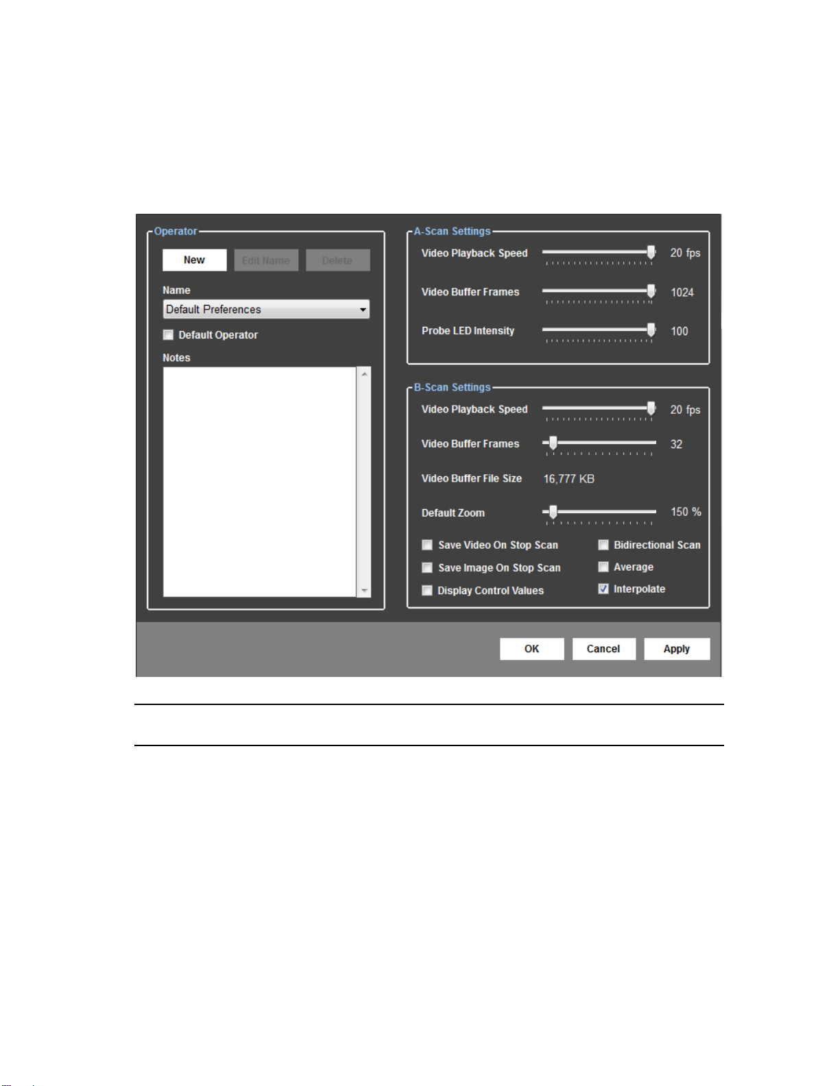
12.2 Operator Preferences
The “Operator Preferences” window provides controls to identify Operators and
configure their preferences. The Operator Preferences window can be accessed by
selecting Preferences →Operator from the Menu Bar.
Note: Refer to the DGH 6000 Scanmate-A or the Scanmate Flex User Guide for
instructions on configuring A-Scan related Operator Preferences.
The New button allows the user to create new operators and assign preferences to the
newly created operator.
The Edit Name button allows the user to make changes to an existing operator’s
preferences. To change an operator’s preferences, click the “Edit” button while the
desired operator’s name is selected in the “Name” combo box. Changes to operator
preferences are saved by clicking the “Apply” button, or can be discarded by clicking
“Cancel”. The “OK” button will save the current settings and close the “Operator
Preferences” window.
The Delete button will delete an operator from the system. When clicked, the user is
prompted for confirmation prior to deleting the operator’s preferences.
Page 15 of 53 8000-INS-UMENG Rev. 4
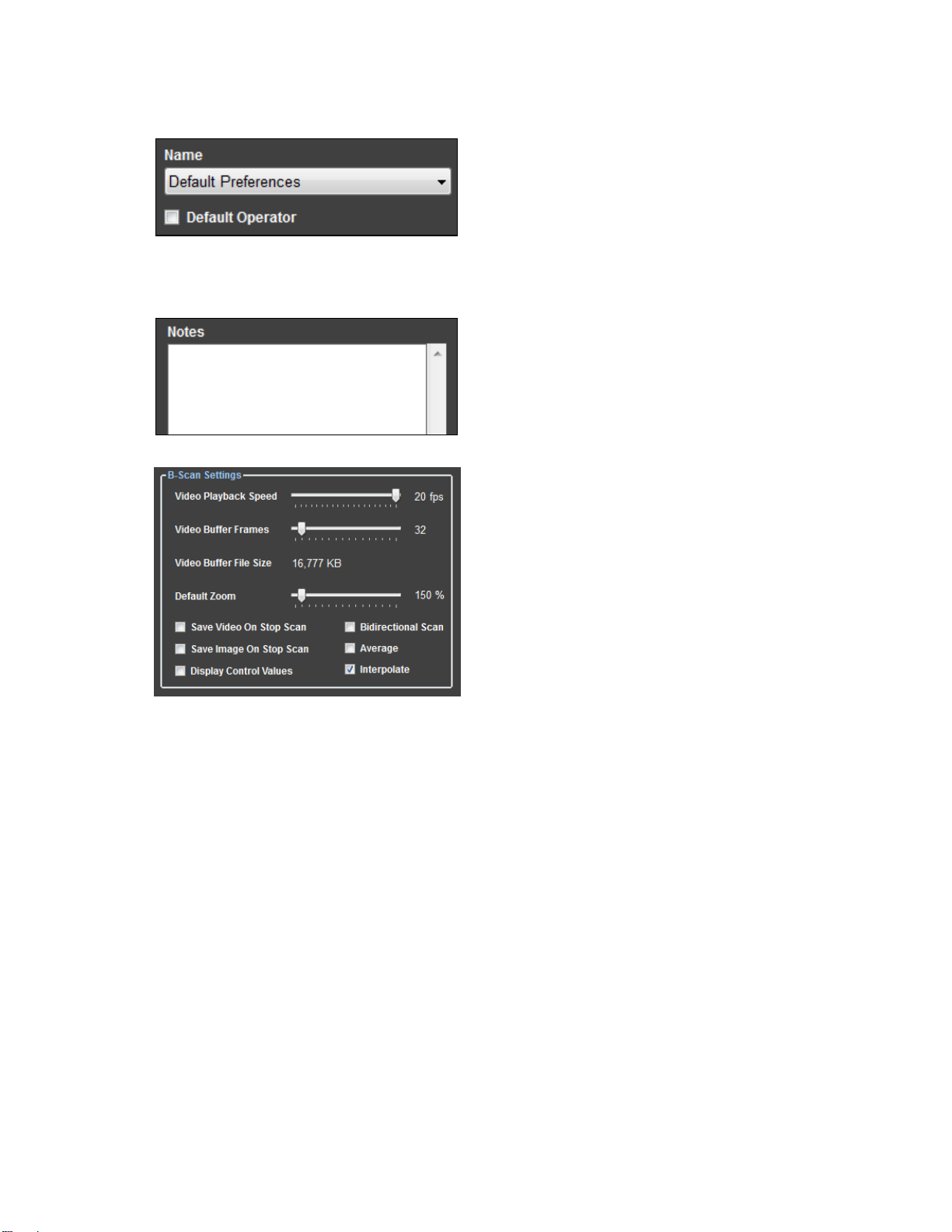
The Name combo box selects an existing
operator from the database to view, edit, or
delete their preferences. Selecting an
operator’s name will display that operator’s
preferences on the screen. The Default
Operator checkbox selects which operator’s
preferences will be automatically loaded when the software is started.
The Notes textbox allows the user to
associate notes to an operator’s preferences.
The B-Scan Video Playback Speed slide bar
adjusts the frames per second (fps) that the B-
Scan video is played for the currently
selected operator. The speed of video
playback can be adjusted from 1 to 20 fps.
The B-Scan Video Buffer Frames slide bar
adjusts the size of the buffer used when
capturing B-Scan video. Moving the slide
bar from left to right increases the number of
frames stored in the buffer. Increasing the
number of frames that can be stored in the buffer allows the user to determine the
amount of video that is captured before it begins to overwrite itself. The video buffer
can be configured to store from 16 to 256 frames.
The B-Scan Default Zoom slide bar adjusts the amount of magnification applied to the
image or video when the zoom button is pressed.
When the Save Video On Stop Scan checkbox is selected, the B-Scan video will
automatically be saved when the scan is stopped.
When the Save Image On Stop Scan checkbox is selected, the last B-Scan frame will
automatically be saved when the scan is stopped.
The Display Control Values checkbox allows the user to select whether or not the
Gain, Intensity and Contrast control values are displayed in the B-Scan image window.
When the Bidirectional Scan checkbox is selected, the B-Scan probe will acquire image
information in both sweep directions.
Page 16 of 53 8000-INS-UMENG Rev. 4
The Average preference turns on the frame-to-frame B-Scan averaging algorithm. For
slower processors, averaging can be turned off to improve display performance at the
expense of image quality.
The Interpolate preference enables or disables the linear interpolation algorithm. For
slower processors, interpolation can be turned off to improve display performance at the
expense of image quality.
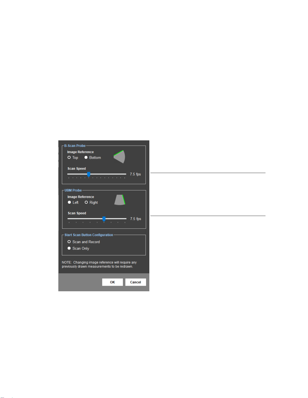
12.3 B-Scan Page Preferences
The B-Scan Page Preferences allow the user to adjust image reference, scan speed
and scan/record settings.
The green line of the Image Reference setting
indicates the side of the image/video that will
correspond to the top position on the probe.
Note: Changing the image reference setting
will change the orientation of the images
stored in the database. If this reference is
changed after images have been acquired, any
measurements overlaying the image will need
to be redrawn.
The Scan Speed setting determines the
number of frames that are acquired per second
during a scan.
The Start Scan Button Configuration setting
determines how the Scan and Record buttons
on the B-Scan page can be configured to
operate together or independently.
Scan and Record: When the Start Scan button is clicked to start a scan, the
software will automatically record video. Recording will stop when the scan is
stopped.
Scan Only: When the Start Scan button is clicked, the scan will start; however,
video will not be recorded until the Record button is clicked. Recording can be
toggled on/off as needed during a scan.

Page 17 of 53 8000-INS-UMENG Rev. 4
12.4 Doctor Preferences
The “Doctor Preferences” window provides controls for the user to identify Doctors and
configure their preferences. Doctor Preferences define the default protocol for
performing A-Scans and IOL Calculations. The Doctor Preferences window can be
accessed by selecting Preferences →Doctor from the Menu Bar.
Note: Refer to the DGH 6000 Scanmate-A or the Scanmate Flex User Guide for
instructions on configuring A-Scan related Doctor Preferences.
The New button allows the user to create new doctor profiles and assign preferences to
the newly created doctor.
The Edit Name button allows the user to make changes to an existing doctor’s
preferences. The user can change a doctor’s preferences by clicking this button while
the desired doctor’s name is selected in the “Name” combo box.
The Delete button deletes a doctor from the system. When clicked, the user is prompted
for confirmation prior to deleting the doctor’s preferences. Once deleted, the doctor will
still exist in the database, but will be marked as inactive.
The Name combo box selects an existing doctor from the database to view, edit, or
delete their preferences. The Default Doctor checkbox selects which doctor will be
automatically placed on the Patient Data and IOL Calculator Screens. If only one doctor
exists, that doctor is automatically set as the default doctor.
The Notes text box is provided to allow the user to associate notes to a doctor’s
preferences.
Page 18 of 53 8000-INS-UMENG Rev. 4
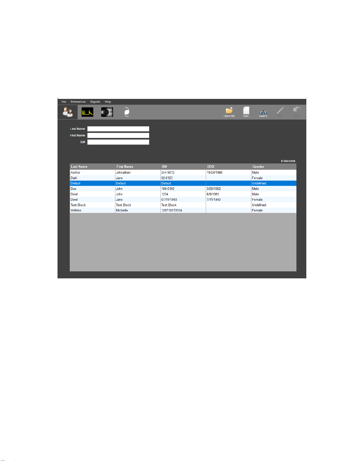
13 The Patient Data Screen
Upon startup, the Scanmate application will automatically open to the Patient Data
Screen in Search Mode. The Patient Data Screen allows the user to Search, Create,
Review and Edit patient records.
13.1 Patient Data Screen Controls
The Patient Data Screen operates in three distinct modes of operation: “Search and
View”, “Edit / Save Data”, and “New Patient.” The action buttons on the top right-hand
side of the screen change availability depending on the current mode of the Patient Data
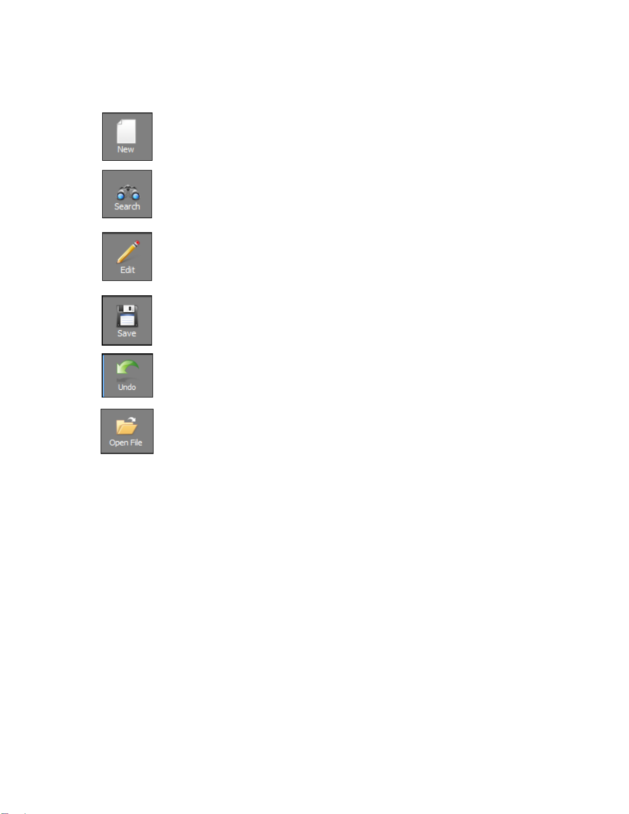
screen. The patient data screen buttons include:
•Open File
•New
•Search
•Edit / Save
•Undo
Page 19 of 53 8000-INS-UMENG Rev. 4
The New button is used to enter new patients in the DGH-Scanmate
database. When clicked, the “Last Name”, “First Name”, and “ID#” combo
boxes change to plain text boxes and allow the user to enter a new patient.
The Search button is used to search for patients in the DGH-Scanmate
database. When selected, the “Patient Info” controls are closed for editing
and all combo boxes become auto-suggest fields.
The Edit button is used to edit patient records in the DGH-Scanmate
database. When selected, the “Patient Info” and “Pre-Operative” controls
become enabled for editing. The Pre-Operative and Post-Operative data is
only needed for performing IOL power calculations.
The Save button saves New or Modified patient records to the DGH-
Scanmate database.
The Undo button allows the user to undo the last changes that were made to
the Patient’s Record. All fields will revert to the most recent saved state.
The Open File button allows the user to open a window to review all
records associated with the selected patient.
13.2 Entering a New Patient
Select the "New”button and enter the following required fields:
•Last Name
•First Name
•ID Number
The ID Number must be unique for each patient. The Scanmate Software will prevent a
new patient from being saved to the database if a patient with the same ID Number
already exists. A default unique ID number is created based on the date and time the
new patient is entered; this can be replaced with any other numbering system desired.
The Patient’s Last Name, First Name and ID Number are required fields and must be
entered before the record can be saved.
The following optional fields can also be entered at this time:
•Patient Date of Birth
•Patient Gender
•Doctor
•Comments

Page 20 of 53 8000-INS-UMENG Rev. 4
•K1 and K2 (K1 and K2 values for OS and OD may be entered from the IOL
Calculator Screen and are only needed for IOL Calculations)
•Desired Refraction (Desired Refraction for OS and OD may be entered from
the IOL Calculator Screen and are only needed for IOL
Calculations)
Select the Save button once all of the desired fields have been entered.
13.3 Searching for a Patient
Select the Search button to search for a patient record that has been saved in the
database. Patients can be searched for by Last Name, First Name, or by ID Number.
To search by Last Name, First Name or ID Number, begin typing in the field you wish
to search. The software will automatically update the patient table to show all the results
that match what has been typed. The desired patient can then be selected from this
patient list.
13.4 Editing a Patient Record
Select the desired patient record to be edited following the steps described in Section
13.3. Once the patient record has been loaded, select the Edit button. All of the editable
fields will change from read-only fields to white, editable text boxes. Once the desired
changes have been made, select the Save button to save the changed record.
Table of contents
Other DGH TECHNOLOGY Diagnostic Equipment manuals


