DGH TECHNOLOGY PACHETTE 500 User manual

DGH 500 (PACHETTE
™
)
ULTRASONIC PACHYMETER
OPERATOR’S MANUAL
TECHNOLOGY, INC.
DGH Technology, Inc. Sales: (800) 722-3883
110 Summit Drive; Suite B www.dghkoi.com Phone: (610) 594-9100
Exton, PA 19341 Fax: (610) 594-0390
SYS.PA5 REV. 05/2000


i
TABLE OF CONTENTS
I. INTRODUCTION.........................................................................................................................................1
II. FEATURES ...................................................................................................................................................2
III. GENERAL DESCRIPTION ........................................................................................................................3
IV. POWER-UP SEQUENCE............................................................................................................................7
V. CONFIGURING THE PACHETTE™........................................................................................................8
VI. OBTAINING PACHYMETRY MEASUREMENTS ..............................................................................11
VII. PROBE QUALITY TEST..........................................................................................................................14
VIII. VERIFYING PACHETTE™CALIBRATION ........................................................................................15
IX. OPTIONAL FEATURES FOR THE PACHETTE™...............................................................................16
IX.A. Automatic Measurement Mode Option............................................................................................16
IX.B. Measurement Averaging Option ......................................................................................................18
IX.C. Printer Interface Option....................................................................................................................20
IX.D. Data Transfer Interface Option.........................................................................................................23
IX.E. Remote Control Interface Option.....................................................................................................25
X. CARE AND MAINTENANCE..................................................................................................................29
X.A. Cleaning Instructions........................................................................................................................29
X.B. Transport and Storage Conditions....................................................................................................29
X.C. Operating Conditions .......................................................................................................................29
X.D. Warranty...........................................................................................................................................30
X.E. Service..............................................................................................................................................30
XI. IMPORTANT NOTES ...............................................................................................................................32
XI.A. Prescription Device ..........................................................................................................................32
XI.B. Tissue Exposure To Ultrasound Energy...........................................................................................32
XI.C. Ultrasonic Intensities........................................................................................................................32
XI.D. Biometric Measurement Capabilities ...............................................................................................33
XI.E. Classification....................................................................................................................................33
XI.F. EMI / EMC Compliance (CE Units Only) .......................................................................................34
XII. APPENDIX A RS232C HARDWARE INTERFACE.....................................................................35
XIII. APPENDIX B DATA TRANSFER FORMAT...............................................................................38
XIV. APPENDIX C REMOTE CONTROL COMMANDS FORMAT ................................................39

ii
LIST OF FIGURES
Figure III-A DGH 500 Front Panel Layout...........................................................................................................3
Figure III-B DGH 500 Back Panel Layout. ..........................................................................................................5
Figure III-C Electronic CALBOX.........................................................................................................................6
Figure XIII-A Format of data stream sent by Pachette™. ......................................................................................38
Figure XIV-A Format of remote control commands..............................................................................................39
Figure XIV-B Format of data responses to remote control commands..................................................................40
Figure XIV-C Status Byte Format..........................................................................................................................41

1
I. INTRODUCTION
Ultrasonic Pachymetry is an integral part of refractive corneal surgery. The DGH 500
(Pachette™) is an ultrasonic pachymeter that uses echo spike techniques to measure the
thickness of the cornea. This is the recommended method for obtaining corneal thickness
measurements because it offers the following advantages:
•Reproducibility
•High accuracy
•Ability to take measurements anywhere on the cornea
•Measurements are not dependent upon patient fixation
•Ease of use
After the corneal thickness has been obtained, the measurement may be used in different
ways. For example, the measurement may be used to determine the appropriate blade
depth when making partial thickness corneal incisions during radial keratotomy, or to
evaluate abnormalities in corneal function causing changes in the corneal thickness, or to
evaluate changes in corneal thickness due to various treatment modes including contact
lenses and various surgical treatments.
The Pachette™was designed to provide a means of obtaining fast, accurate, corneal
thickness measurements with an instrument that is simple to use, economical, and ultra-
portable. We invite you to read this manual carefully to discover how quickly and easily
the Pachette™can be integrated into your practice.

2
II. FEATURES
The Pachette™is manufactured with high quality components that are designed and built
using the latest technological concepts. The result is an advanced and powerful
pachymeter that offers practicality and reliability. The following features are just a
sample of the characteristics and capabilities of the Pachette™.
Standard Features
•Simple to use. Turn on power and the Pachette™is ready to take measurements.
•Automatically stores up to 33 measurements.
•Simultaneously displays actual and biased measurements by position location.
•Large ½ inch LED character displays allow easy visibility from a distance over a
large viewing angle and in all lighting conditions.
•Proven measurement algorithm which yields accurate, reproducible measurements in
a fraction of a second.
•Ultra-Portable. Compact and light weight to allow easy transfer from the office to the
hospital. Adjustable tilt stand/handle for ease of viewing.
•Operator feedback. Audible signal indicates when a valid measurement is complete.
•Dual position foot switch for initiating measurements and memory storage.
•Personalized configuration. User-friendly front panel allows selection of number of
positions to be measured, speed of sound used to calculate corneal thickness, and type
and amount of bias based on incision depth factor.
•Configuration memory. Once personally configured for the operator, non-volatile
memory provides permanent storage of configuration data, even when the Pachette™
is turned off.
Optional Features
•Automatic measurement mode for operation without a foot switch.
•Measurement averaging of corneal positions designated by the operator.
•Printer interface for sending pachymetry data to a serial printer.
•Data transfer interface for sending pachymetry data to a personal computer.
•Remote control interface for operating the Pachette™from a personal computer.
3
III. GENERAL DESCRIPTION
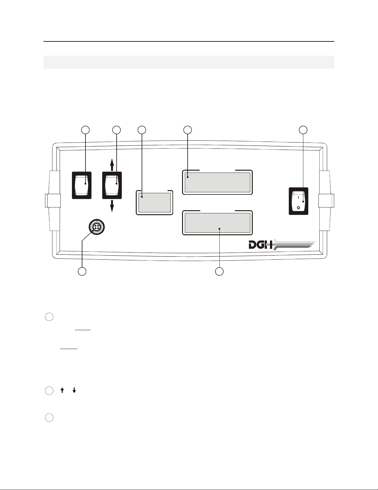
Front Panel
ULTRASONIC PACHYMETER
PQT
CLEAR
PROBE
POWER
PACHETTE
TM
POSITION
A
CTUAL DATA
BIASED DATA
TECHNOLOGY, INC.
41 2 3 5
6 7
PQT / Clear Switch
PQT – Performs a Probe Quality Test when pressed and released. Used to
initiate the main configuration mode when pressed and held.
Clear – Used to clear all measurements from memory and re-initiate measurements
at position 1 when pressed and released. If the printer interface option is installed, a
print out will also be initiated. Used to initiate the velocity configuration mode when
pressed and held.
/ Switch
Used to program options and numerical values presented on the displays.
Position Display
A 2-character LED display used to correlate a given measurement with a
specific location on the cornea. It is the operator’s responsibility to maintain a record
Figure III-A DGH 500 Front Panel Layout.
1
2
3

4
of the position number to the actual corneal location. This record may be maintained
on a chart such as the “Cornel Thickness Chart” supplied with each Pachette™. This
display is also used to present setup information to the operator when configuring
the Pachette™.
Actual Data Display
A 4-character LED display used to present corneal thickness measurements to
the operator. All measurements are given in microns (µm) and are based on a
corneal velocity of 1640m/s unless the operator changes the velocity. This display is
also used to present setup information to the operator when configuring the
Pachette™.
Power Switch
Pressing “1” side of switch turns the Pachette™on. Pressing “0” side of switch
turns the Pachette™off.
Probe Interface
Front panel connector which mates to the connector on the Probe cable.
Biased Data Display
A 4-character LED display used to present biased corneal measurements to the
operator. All biased measurements are given in microns (µm) and are based on a
corneal velocity of 1640m/s unless the operator changes the velocity. The bias can
be either a percentage (1-199%) of the actual measurement or a fixed offset (±1-
199µm). This display is also used to present setup information to the operator when
configuring the Pachette™.
4
5
6
7

5
Back Panel
Pachette
TM
Model-DGH 500
SN-3048
110 SUMMIT DRIVE
SUITE B
EXTON, PA 19341
USA (610) 594-9100
FOR PROFESSIONAL USE ONLY.
DANGER:
EXPLOSION HAZARD. DO NOT USE IN PRESENCE OF FLAMMABLE
ANESTHETICS, GASES OR OXYGEN-RICH ATMOSPHERE.
DGH 1999 DGH-500BPLCE
INPUT
100-240V~
50/60Hz
0.3A
REPLACE
FUSES
AS
MARKED
T0.5A
250V
0459
12 34
Fuse Holder
Location of AC input fuse(s). If a fuse needs replacing, always replace the fuse
as marked.
Model & Serial Numbers
Location of model and serial numbers used to identify the unit.
Foot Pedal Interface
Phone jack that accepts the phone plug attached to the end of the foot pedal cable.
CE Certification Marks
These marks are used to identify CE certified units. (CE certification is optional)
Figure III-B DGH 500 Back Panel Layout.
1
2
3
4
6
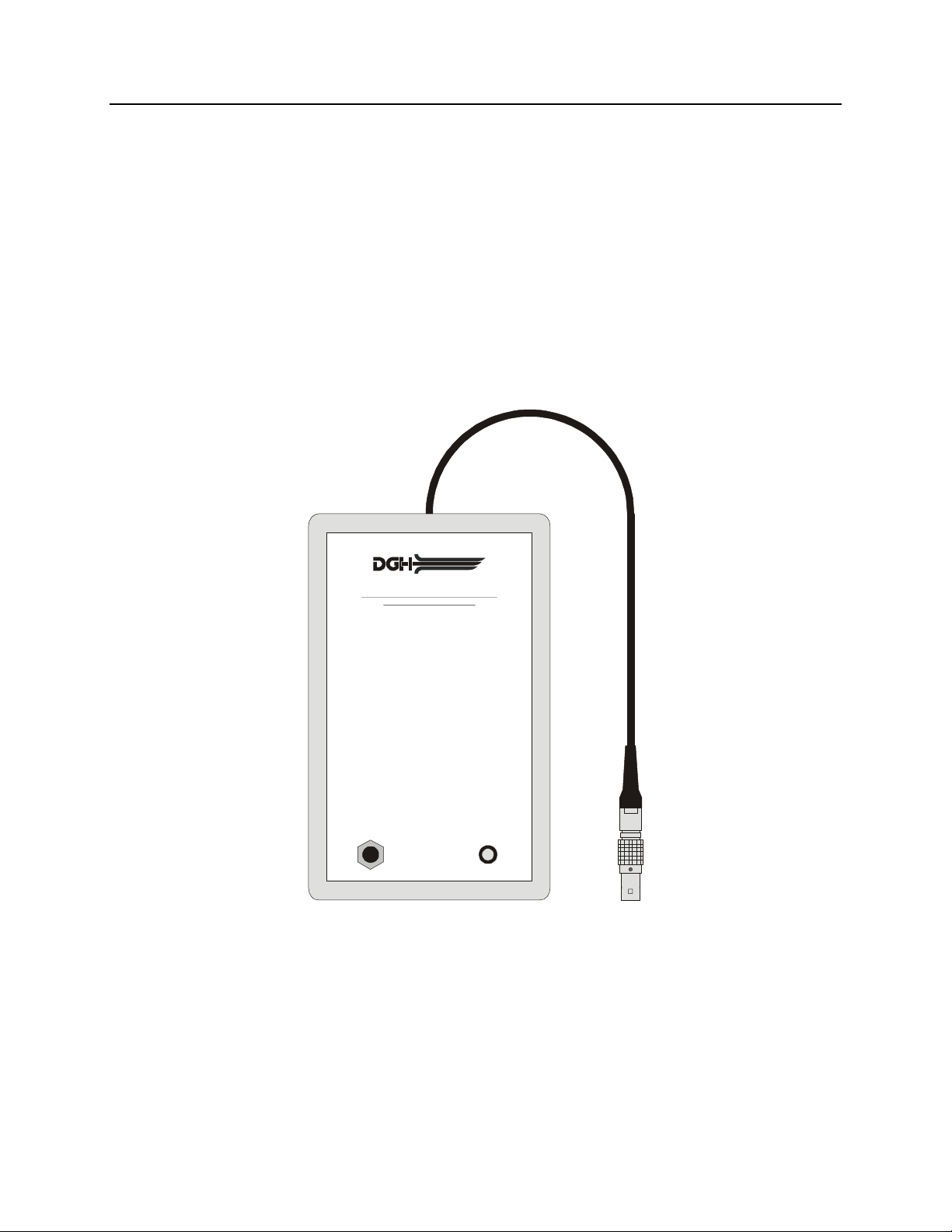
Calibration Standard
To check Pachymeter calibration, an electronic CalBox (below) is used to simulate the
thickness of the cornea. Instructions for using the CalBox are given in section VIII and
they are also printed on the Calbox label.
TECHNOLOGY, INC.
DGH 500 PACHETTE™CALIBRATION BOX
OPERATING INSTRUCTIONS
1. With Pachette turned off, connect probe to front panel.
2. Enter the Demo mode by holding in the switch and
turning on the Pachette.
3. Afterpower-upiscompleted,thedisplaywillindicate:
Positon = 1 Actual Data = 0 Biased Data = 0
4. Disconnect probe and connect CalBox to the Pachette.
5. PressCalBoxbuttonuntilpowerLEDlights.
If the LED fails to light or goes out before the test
sequence is completed, or if “POORAPPL” is displayed,
replacethe9Valkalinebattery.
If no measurements are taken within 2½ minutes after
the CalBox button is pressed, the CalBoxwill turnoff.
6. If“Auto Mode” is enabled, the Pachete willbegin taking
measurements. If “Auto Mode” is not enabled, then use
thefootpedaltotakemeasurements.
7. Observe actual measurement values of 200
8. Before taking any corneal measurements,
re-connect the probe and exit the Demo mode by
pressing andthenpress .
Ï
Important!
CLEAR PQT
µm thru
1000µm in steps of 100µm. (ALKunits start at 100µm)
All values are based on a corneal velocity of 1640m/s
and should be within ± 5µm. If any measurements are
outoftolerance,contactDGHTechnology,Inc.
Figure III-C Electronic CALBOX

7
IV. POWER-UP SEQUENCE
1. Plug the AC cord into a three-prong outlet.
2. Verify that the foot pedal is plugged into the rear panel.
3. Verify that the probe is connected to the front panel.
4. Turn on the unit.
5. The Pachette™performs an internal self-test function and then tests all the displays
by sequencing through the numbers 0 to 9.
6. The Pachette™initiates a Probe Quality Test and then displays the results. A probe
of satisfactory quality should yield a Probe Quality Factor (PQF) of 100%. This will
be indicated on the display as “PQF 100%” for approximately two seconds. Any
other message indicates that the probe quality is not satisfactory and pachymetry
measurements will be inhibited. Refer to section VII for a detailed description of the
Probe Quality Test.
7. The power-up sequence is finished when the Position display is set to “1”, and the
Actual/Biased Data displays are both set to “0”. The Pachette™is now ready to take
corneal measurements. If any default parameters need to be modified, refer to
section V. Otherwise, refer to section VI for a detailed description of the proper
method for obtaining measurements.

8
V. CONFIGURING THE PACHETTE
™
Configuration Overview
The Pachette™has been designed to allow the operator to modify certain default
parameters to tailor the instrument to meet one’s needs. Once modified, these parameters
are permanently stored in non-volatile memory and are automatically recalled each time
the unit is powered up. To change a parameter, the operator must first enter one of two
configuration modes: the Main Configuration Mode, or the Velocity Configuration
Mode. The following procedures explain how to enter each mode and change the default
parameters.
The Main Configuration Mode
A complete list of all the parameters for the Main Configuration Mode is given in Table
1. The white sections of this table identify the parameters that are accessible on every
Pachette™. The shaded sections of the table identify parameters that are only accessible
when optional features have been added to the basic Pachette™(for a detailed description
of all available options refer to section IX). Use the following procedure to enter the main
configuration mode and modify the parameters that are accessible.
1. Press and hold the PQT switch until the message “PACH CNFG” appears on the
display.
2. Release the PQT switch. The designator “P1” and parameter “TYPE” should now
be displayed. (A designator is a label that helps to identify a configurable
parameter.)
3. To select a new value for the designated parameter, press and release the ↑or ↓
cursor switch. To scroll through the available parameter values press and hold the ↑
or ↓cursor switch.
4. To advance to the next parameter, press and release the PQT switch.
5. Repeat steps 3 and 4 to modify any remaining parameter values.
6. To save the new parameter values and exit the main configuration mode, press and
release the CLEAR switch
7. Pachymetry measurements may now be taken. Refer to section VI for a detailed

9
description of the proper method for obtaining measurements.
Designator Parameter
(default value) Range Description Associated
Option(s)
P1 TYPE
(%) %
+
-
Selects the type of bias to be implemented:
(%) Percentage of the Actual Data.
(+) Fixed offset added to the Actual Data.
( - ) Fixed offset subtracted from Actual Data.
Basic
Pachette™
P2 BIAS
(100%) 1 to 199 Selects the amount of bias. Basic
Pachette™
P3 PNTS
(33) 1 to 33 Selects the number of measurement points. Basic
Pachette™
I1 INTF
(NONE) NONE
PRNT
XFER
RMTE
RS232C serial interface mode of operation:
NONE = interface is disabled.
PRNT = connection to printer.
XFER = data transfer to a computer.
RMTE = remote operation from a computer.
Printer
Data Transfer
Remote
I2 * BAUD
(9600) 300
600
1200
2400
4800
9600
Sets the data transfer rate in bits per second
(bps) for the RS232C serial interface. Printer
Data Transfer
Remote
M1 MODE
(MANL) MANL
AUTO Selects between the Automatic and Manual
measurement modes. Auto Mode
M2 * DLY1
(1.0) 1.0 to 9.5 sec Period of time before the unit will
automatically store the current measurement
and advance to the next measurement position.
Auto Mode
M3 * DLY2
(2.0) 1.0 to 9.5 sec Period of time after poor applanation occurs
before the unit will automatically advance to
the next position.
Auto Mode
A1 DISP
(BIAS) BIAS
AAVG
BAVG
Selects mode of the Biased/Average display:
BIAS = biased measurement calculated from
the actual measurement. (no averaging)
AAVG = actual average associated with the
current measurement position.
BAVG = biased average associated with the
current measurement position.
Measurement
Averaging
A2 * P 2
(A1) P= 2 to 33
A = 1 to 4 Permits the operator to specify which average
number (A1 to A4) is to be associated with a
given measurement position (P2 to P33).
Measurement
Averaging
* Depending upon the selection of a previous parameter value, these parameters may not appear.
Table 1 Parameters Of The Main Configuration Mode And Associated Options

10
The Velocity Configuration Mode
The Velocity Configuration Mode is accessible on every Pachette™. This mode permits
the operator to modify the corneal velocity setting of the pachymeter. Corneal velocity is
used in the calculation of all corneal measurements. Therefore, it is important that the
value for the corneal velocity setting be correct. The currently accepted value for the
speed of sound through the cornea is 1640m/s. This is also the default value for the
corneal velocity setting in the Pachette™. If the operator wishes to modify the default
value for any reason, the following procedure can be used to enter the velocity
configuration mode and change the corneal velocity parameter.
1. Press and hold the CLEAR switch until the message “VEL” appears on the Actual
Data display.
2. Release the CLEAR switch. The default corneal velocity of 1640m/s should now be
displayed (unless an operator had previously changed this value).
3. To modify the corneal velocity, press and release the ↑or ↓cursor switch to
increase or decrease the number being displayed. Pressing and releasing the switch
changes the display in one-count steps. Pressing and holding the switch enables the
scroll mode. The range of values for this parameter is 1000 to 1999m/s.
4. To save and exit the velocity configuration mode, press and release the CLEAR
switch.
5. Pachymetry measurements may now be taken. Refer to section VI for a detailed
description of the proper method for obtaining measurements.

11
VI. OBTAINING PACHYMETRY MEASUREMENTS
The basic Pachette™obtains pachymetry measurements by using a foot pedal to initiate
the measurement sequence. This method of obtaining measurements is referred to as the
“Manual Mode”. If it is desired, an option is available from the factory that allows
measurements to be taken without the use of a foot pedal. This option is referred to as the
“Auto Mode”. When the Auto Mode is enabled, measurements are taken automatically
whenever the tip of the probe is properly applanated onto the cornea.
The exact method for obtaining pachymetry measurements will be different depending
upon which mode has been enabled on the Pachette™. Section IX.A explains how to
switch between Auto and Manual modes for those units equipped with the Auto Mode
option. For convenience, the procedures for using both measurement modes are given
below. Be sure to follow the appropriate procedure for how the Pachette™is configured.
Obtaining Measurements In Auto Mode
1. Perform the Power-Up Sequence as described in section IV.
2. Position the Pachette™for easy visibility during patient examination.
3. With the patient in supine position and visualizing a fixation spot on the ceiling,
position the tip of the probe onto the cornea at the location the operator has defined
as position #1. Once the probe tip is aligned properly, the Pachette™will
automatically attempt to take a measurement.
4. When a measurement is obtained, a short “beep” will occur to indicate that the
measurement has been stored in memory. The measurement is shown on the Actual
Data display for a time interval known as Delay 1 (default = 1 sec.). After Delay 1
expires, the display will advance to position #2 and two short “beeps” will occur to
indicate that the unit is ready to take the next measurement.
If a measurement is not obtained within 3 seconds, a long “beep” will occur to
indicate that a poor applanation has happened. A message of “POOR APPL” is also
displayed for a time interval known as Delay 2 (default = 2 sec.). After Delay 2
expires, the display will advance to position #2 and two short “beeps” will occur to
indicate that the unit is ready to take the next measurement.
Notes: The audible feedback is provided so that the operator can concentrate on
probe tip alignment and positioning. For instructions on changing the length of

12
Delay 1 and/or Delay 2 refer to section IX.A
If the message of “POOR APPL” keeps appearing on the display, check to insure the
probe tip actually touches the cornea and is perpendicular to the corneal surface. If a
measurement is still not obtained, perform the Probe Quality Test by pressing the
PQT switch. The Probe Quality Test can be performed at any point in the
measurement sequence.
5. Whenever an acceptable measurement has been made, the Actual Data display
indicates the corneal thickness in microns. All thickness measurements are based on
a corneal velocity of 1640 m/sec unless programmed differently by the operator.
Simultaneously, the Biased Data display indicates a biased corneal thickness (in
microns) that is based on surgical requirements as defined by the operator. Refer to
section V for instructions on programming the corneal velocity, bias type, and/or
amount of bias.
6. All measurements can be reviewed on the display by either using the ↑↓switch on
the front panel or by pressing the left and right sides of the foot pedal. A new
measurement may be taken at any position by causing the appropriate position
number to appear on the display and then retaking the new measurement.
7. All measurements remain in memory until the CLEAR switch is pressed or the
Pachette™is turned off. Press CLEAR to erase all measurements and re-initialize
the Pachette™for a new measurement sequence starting at position #1.
Obtaining Measurements In Manual Mode
1. Perform the Power-Up Sequence as described in section IV.
2. Position the Pachette™for easy visibility during patient examination.
3. With the patient in supine position and visualizing a fixation spot on the ceiling,
position the tip of the probe onto the cornea at a location that the operator has
defined as position #1. Once the probe tip is aligned properly, press the right side of
the foot pedal to take a measurement.
4. When a measurement is obtained, a short “beep” will occur to indicate that the
measurement has been stored in memory. At the same time, the measurement is
shown on the Actual Data display.
If a measurement is not obtained within 3 seconds, a long “beep” will occur to
indicate that a poor applanation has happened. At the same time, the message

13
“POOR APPL” is displayed.
Note: The audible feedback is provided so that the operator can concentrate on
probe tip alignment and positioning.
If the message of “POOR APPL” keeps appearing on the display, check to insure the
probe tip actually touches the cornea and is perpendicular to the corneal surface. If a
measurement is still not obtained, perform the Probe Quality Test by pressing the
PQT switch. The Probe Quality Test can be performed at any point in the
measurement sequence.
5. Whenever an acceptable measurement has been made, the Actual Data display will
indicate the corneal thickness in microns. All thickness measurements are based on a
corneal velocity of 1640 m/sec unless programmed differently by the operator.
Simultaneously, the Biased Data display will indicate a biased corneal thickness (in
microns) that is based on surgical requirements as defined by the operator. Refer to
section V for instructions on programming the corneal velocity, bias type, and/or
amount of bias.
6. After obtaining an acceptable measurement for position #1, press the left side of the
foot pedal once to advance the display and the unit will be ready to take the next
measurement at position #2.
7. All measurements can be reviewed on the display by either using the ↑↓switch on
the front panel, or by pressing the left side of the foot pedal. A new measurement
may be taken at any position by causing the appropriate position number to appear
on the display and then taking the new measurement at that position.
8. All measurements remain in memory until the CLEAR switch is pressed or the
Pachette™is turned off. Press CLEAR to erase all measurements and re-initialize
the Pachette™for a new measurement sequence starting at position #1.

14
VII. PROBE QUALITY TEST
Probe Quality Test Overview
The purpose of the Probe Quality Test (PQT) is to allow the operator to check the quality
of the ultrasonic probe when connected to the front panel. When the PQT switch is
pressed, ultrasonic waves are emitted from the piezoelectric element in the transducer
housing and transmitted through the plastic cone. A return signal (echo) is created when
the ultrasonic waves pass through the end of the plastic cone into free air. This echo
signal is received by the piezoelectric element, and then amplified and measured within
the unit. The magnitude of the echo signal is compared to the magnitude of the echo
signal when the unit was originally calibrated at the factory. Depending on the results of
this comparison, a message stating the quality of the probe is displayed on the front
panel.
1. If installed, remove the plastic protective sleeve from the probe tip.
2. Connect the probe to the front panel connector labeled “PROBE”.
3. Press and release the PQT switch. The results of the test will be shown on the front
panel by displaying one of the following four messages:
“PQF = 100%”
This indicates that the “Probe Quality Factor” is optimum and the probe has passed
the Probe Quality Test. Pachymetry measurements may now be taken.
“CHK PRBE”
This message usually means the tip of the probe is wet. However, if drying the tip of
the probe fails to produce an acceptable probe quality test, this message may indicate
that the probe has degraded and will require replacement.
“NO PRBE”
This message occurs when: (1) the probe connector is not mated or is improperly
mated to the connector on the front panel, or (2) the probe is defective.
“PQT FAIL”
This message usually indicates a hardware failure occurred within the unit and the
unit must be returned for repair.

15
VIII. VERIFYING PACHETTE
™
CALIBRATION
Pachymeter calibration is verified by using the electronic calibration box (CalBox) that is
supplied with the Pachette™(see Figure III-C). It is important to realize that the CalBox
does not calibrate the pachymeter. The CalBox generates a sequence of precise,
predetermined thicknesses that can be measured by the pachymeter. The values of these
thicknesses have been purposely selected to span the full measurement range of the unit.
Therefore, by measuring these predetermined thicknesses, the operator can quickly verify
that the pachymeter is properly calibrated.
Procedure For Verifying Calibration
1. With the Pachette™turned off, connect the probe to the front panel.
2. Enter the Demo mode by holding in the ↑switch and turning on the Pachette™.
3. After power-up is completed, the display will indicate:
Position = 1 Actual Data = 0 Biased Data = 0
4. Disconnect the probe and connect the Calbox to the Pachette™.
5. Press the Calbox button until the LED lights.
If the LED fails to light or goes out before the test sequence is completed, or if
"POOR APPL" is displayed, then replace the 9V alkaline battery.
If no measurements are taken with 2½ minutes after the CalBox button is pressed, the
Calbox will automatically turn off.
6. If “Auto Mode” is enabled, the Pachette™will automatically begin taking
measurements. If “Auto Mode” is not enebled, then use the foot pedal to take
measurements.
7. Observe actual measurement values of 200µm thru 1000µm in steps of 100µm. (ALK
units start at 100µm)
All values are based on a corneal velocity of 1640m/s and should be within ±5µm. If
any measurements are out of tolerance, contact DGH Technology, Inc.
8. Important! Before taking any corneal measurements, re-connect the probe and exit
the Demo mode by pressing CLEAR and then press PQT.

16
IX. OPTIONAL FEATURES FOR THE PACHETTE
™
The Pachette™has been designed as an economical and easy to use instrument. A basic
unit contains a variety of features that the operator will find useful when obtaining
pachymetry measurements. To further enhance the functionality of the Pachette™, DGH
Technology, Inc. also offers five additional options that can be installed when the unit is
purchased. Any combination of options may be selected to tailor the unit to fit one’s
particular requirements. The options that are currently available for the Pachette™are:
1. Automatic Measurement Mode Option – Allows measurements to be taken
without the use of a foot switch.
2. Measurement Averaging Option – Permits the averaging of a group of
measurements that are defined by the operator.
3. Printer Interface Option – Allows a serial printer to be connected to the
Pachette™for obtaining a hard copy of pachymetry data.
4. Data Transfer Interface Option – Allows pachymetry data to be transferred to a
personal computer for the purpose of archiving, display formatting,
predictability computations, etc.
5. Remote Control Interface Option – Permits the Pachette™to be controlled
externally by a personal computer. This option is intended primarily for
refractive surgery software packages, resident on a personal computer, that
require access to pachymetry data.
The following sections give a description of each option and also explain how to use
them.
IX.A. Automatic Measurement Mode Option
The Automatic Measurement Mode (or Auto Mode) is a unique operating feature of the
Pachette™. Auto Mode allows corneal measurements to be obtained and stored without
the use of a foot switch. This is achieved by sensing when the probe is placed on the
cornea and when it is removed. With the assistance of two user programmable time
delays, the operator may customize the Auto Mode to permit rapid corneal mapping
while still reviewing measurements during the process. Auto Mode also permits taking
multiple measurements at the same corneal position, saving the last measurement that
was obtained.
Table of contents
Other DGH TECHNOLOGY Diagnostic Equipment manuals


