DH Instruments E-DWT-10000-AF User manual

© 2008 DH Instruments, a Fluke Company
E-DWT-10000-AF
Electronic Deadweight Tester
Operation and Maintenance Manual
NSN 6685-01-566-1341

E-DWT-10000-AF OPERATION AND MAINTENANCE MANUAL
© 2008 DH Instruments, a Fluke Company
High pressure liquids and gases are potentially hazardous. Energy stored in these liquids and gases can
be released unexpectedly and with extreme force. High pressure systems should be assembled and operated
only by personnel who have been instructed in proper safety practices.
This instrument is not to be operated in any other manner than that specified by the manufacturer.
© 2008 DH Instruments, a Fluke Company All rights reserved.
Information in this document is subject to change without notice. No part of this document may be reproduced or transmitted in any
form or by any means, electronic or mechanical, for any purpose, without the express written permission of DH Instruments, a
Fluke Company 4765 East Beautiful Lane, Phoenix AZ 85044-5318, USA.
DH Instruments makes sincere efforts to ensure accuracy and quality of its’ published materials; however, no warranty, expressed
or implied, is provided. DH Instruments disclaims any responsibility or liability for any direct or indirect damages resulting from the
use of the information in this manual or products described in it. Mention of any product or brand does not constitute an
endorsement by DH Instruments of that product or brand. This manual was originally composed in English and was subsequently
translated into other languages. The fidelity of the translation cannot be guaranteed. In case of conflict between the English version
and other language versions, the English version predominates.
Products described in this manual are manufactured under international patents and one or more of the following U.S. patents:
5,142,483; 5,257,640; 5,331,838; 5,445,035. Other U.S. and international patents pending.
AutoRange, AutoZ, DH Instruments,DH,DHI, CalTool, COMPASS, E-DWT, RPM4-E-DWT, QDUT, Q-RPT and SDS are
trademarks, registered and otherwise, of DH Instruments, a Fluke Company.
Document No. 3338242
DHI Document No. 550166b
080624
Printed in the USA

TABLE OF CONTENTS
Page I © 2008 DH Instruments, a Fluke Company
T
TA
AB
BL
LE
E
O
OF
F
C
CO
ON
NT
TE
EN
NT
TS
S
TABLE OF CONTENTS...............................................................I
TABLES..................................................................................V
FIGURES................................................................................VI
ABOUT THIS MANUAL ............................................................VII
1. INTRODUCTION .................................................................1
1.1 PRODUCT OVERVIEW ...........................................................................................................................1
1.2 SPECIFICATIONS ...................................................................................................................................2
1.2.1 GENERAL SPECIFICATIONS.......................................................................................................................2
1.2.2 BATTERY AND CHARGER PACK ...............................................................................................................3
1.2.3 PRESSURE MEASUREMENT SPECIFICATIONS .......................................................................................3
1.2.3.1 REFERENCE PRESSURE TRANSDUCERS (RPT) .................................................................................3
1.2.3.2 ON-BOARD BAROMETER ........................................................................................................................4
1.3 VIEWS AND SCHEMATICS ....................................................................................................................4
1.3.1 E-DWT-10000-AF VIEWS..............................................................................................................................4
1.3.1.1 FRONT VIEW.............................................................................................................................................4
1.3.1.2 REAR VIEW ...............................................................................................................................................5
1.3.2 RPM4-E-DWT REFERENCE PRESSURE MONITOR VIEWS......................................................................5
1.3.2.1 FRONT PANEL ..........................................................................................................................................5
1.3.2.2 REAR PANEL.............................................................................................................................................6
1.3.3 BATTERY/CHARGER PACK VIEWS ...........................................................................................................6
1.3.4 E-DWT-10000-AF DIMENSIONS...................................................................................................................7
1.3.5 E-DWT-10000-AF HYDRAULIC SCHEMATIC..............................................................................................7
2. INSTALLATION ..................................................................9
2.1 UNPACKING AND INSPECTION............................................................................................................9
2.1.1 REMOVING FROM PACKAGING .................................................................................................................9
2.1.2 INSPECTING CONTENTS.............................................................................................................................9
2.2 SITE REQUIREMENTS..........................................................................................................................10
2.3 SETUP ...................................................................................................................................................10
2.3.1 PREPARING FOR OPERATION.................................................................................................................10
2.3.2 SETTING UP AUTOTEST FILES ................................................................................................................10
2.4 OPERATIONAL CHECK........................................................................................................................11
2.4.1 RPM4-E-DWT PRESSURE MEASUREMENT ............................................................................................11
2.4.2 E-DWT PRESSURE GENERATION AND CONTROL ................................................................................11
2.5 SHORT TERM STORAGE.....................................................................................................................12
2.6 LONG TERM STORAGE, PREPARATION FOR SHIPPING.................................................................13
3. OPERATION..................................................................... 15
3.1 GENERAL OPERATING PRINCIPLES.................................................................................................15
3.1.1 MULTIPLE RANGES (HI AND LO Q-RPT, AUTORANGE)........................................................................15
3.1.2 PRESSURE READY/NOT READY..............................................................................................................16
3.1.3 AUTOMATED TEST AND CALIBRATION SEQUENCES..........................................................................16
3.1.4 TYPICAL OPERATING SEQUENCE TO RUN A TEST..............................................................................16
3.2 TEST PORT CONNECTION..................................................................................................................17
3.2.1 RPM4-E-DWT ATM PORTS ........................................................................................................................18
3.3 BATTERY/CHARGER PACK................................................................................................................18
3.4 SELECTING THE HI OR LO Q-RPT......................................................................................................19
3.5 PRESSURE GENERATION AND ADJUSTMENT.................................................................................22

E-DWT-10000-AF OPERATION AND MAINTENANCE MANUAL
© 2008 DH Instruments, a Fluke Company Page II
3.5.1 FILLING AND PRIMING, RESERVOIR PUMP............................................................................................22
3.5.2 PRESSURE GENERATION AND ROUGH ADJUSTMENT, VARIABLE VOLUME...................................23
3.5.3 PRESSURE FINE ADJUSTMENT, FINE ADJUST VALVE ........................................................................24
3.6 RPM4-E-DWT USER INTERFACE........................................................................................................24
3.6.1 MAIN RUN SCREEN....................................................................................................................................24
3.6.2 FUNCTION / DATA KEYPAD LAYOUT AND PROTOCOL........................................................................26
3.6.3 OPTIONAL REMOTE [ENT] (ENTER) FOOTSWITCH...............................................................................26
3.6.4 SOUNDS......................................................................................................................................................27
3.7 RPM4-E-DWT DIRECT FUNCTION KEYS............................................................................................27
3.7.1 SUMMARY...................................................................................................................................................27
3.7.2 [RANGE]......................................................................................................................................................28
3.7.3 [UNIT]...........................................................................................................................................................29
3.7.4 [MODE] ........................................................................................................................................................30
3.7.5 [AUTORANGE]............................................................................................................................................30
3.7.6 [LEAK CK]...................................................................................................................................................32
3.7.7 [DISPLAY]....................................................................................................................................................33
3.7.7.1 AVG (AVERAGE).....................................................................................................................................34
3.7.7.2 RATE........................................................................................................................................................35
3.7.7.3 DEV (DEVIATION) ...................................................................................................................................36
3.7.7.4 RPT ..........................................................................................................................................................37
3.7.7.5 HI/LO........................................................................................................................................................38
3.7.7.6 FREEZE ...................................................................................................................................................38
3.7.7.7 CLEAN .....................................................................................................................................................39
3.7.8 [HEAD].........................................................................................................................................................39
3.7.9 [SDS]............................................................................................................................................................41
3.7.10 [AUTOZ].......................................................................................................................................................41
3.7.11 [ENT] (RUN AUTOTEST) ............................................................................................................................42
3.7.11.1 AUTOTEST INITIALIZATION...................................................................................................................43
3.7.11.2 TEST EXECUTION ..................................................................................................................................44
3.8 [SETUP].................................................................................................................................................46
3.8.1 <1RANGE> ..................................................................................................................................................46
3.8.1.1 SAVING AN AUTORANGE RANGE ........................................................................................................46
3.8.1.2 DELETING AUTORANGE RANGES .......................................................................................................47
3.8.2 <2RES> (RESOLUTION).............................................................................................................................47
3.8.3 <3STAB> (STABILITY) ...............................................................................................................................48
3.8.4 <4UL> (UPPER LIMIT) ................................................................................................................................49
3.8.4.1 OVER PRESSURE FUNCTION...............................................................................................................49
3.8.5 <5ATEST>....................................................................................................................................................50
3.8.5.1 DATA........................................................................................................................................................50
3.8.5.2 FILE..........................................................................................................................................................51
3.9 [SPECIAL] .............................................................................................................................................53
3.9.1 <1AUTOZ>...................................................................................................................................................54
3.9.2 <2REMOTE>................................................................................................................................................55
3.9.2.1 <1COM1, 2COM2> ..................................................................................................................................56
3.9.2.2 <3IEEE-488>............................................................................................................................................56
3.9.2.3 <4FORMAT>............................................................................................................................................56
3.9.2.4 <5RS232 SELF-TEST>............................................................................................................................56
3.9.3 <3HEAD>.....................................................................................................................................................57
3.9.4 <4SDS>........................................................................................................................................................57
3.9.5 <5PREFS> ...................................................................................................................................................57
3.9.5.1 <1SCRSVR> ............................................................................................................................................58
3.9.5.2 <2SOUND> ..............................................................................................................................................58
3.9.5.3 <3TIME>...................................................................................................................................................59
3.9.5.4 <4ID>........................................................................................................................................................59
3.9.5.5 <5LEVEL> (SECURITY) ..........................................................................................................................60
3.9.6 <6PUNIT>.....................................................................................................................................................62
3.9.7 <7INTERN>..................................................................................................................................................63
3.9.7.1 <1BARO>.................................................................................................................................................64
3.9.7.2 <2READRT> ............................................................................................................................................64
3.9.7.3 <3RPT2X>................................................................................................................................................65
3.9.7.4 <4LO VNT> ..............................................................................................................................................65
3.9.7.5 <5LOG>....................................................................................................................................................65
3.9.8 <8CAL>........................................................................................................................................................66
3.9.9 <9RESET> ...................................................................................................................................................66
3.9.9.1 <1SETS>..................................................................................................................................................66
3.9.9.2 <2 UNITS> ...............................................................................................................................................67
3.9.9.3 <3ATEST>................................................................................................................................................67
3.9.9.4 <4 CAL> ...................................................................................................................................................67
3.9.9.5 <5 ALL>....................................................................................................................................................68

TABLE OF CONTENTS
Page III © 2008 DH Instruments, a Fluke Company
4. REMOTE OPERATION ....................................................... 69
4.1 OVERVIEW............................................................................................................................................69
4.2 INTERFACING.......................................................................................................................................69
4.2.1 RS232 INTERFACE.....................................................................................................................................69
4.2.1.1 COM1.......................................................................................................................................................69
4.2.1.2 COM2.......................................................................................................................................................70
4.3 PROGRAMMING FORMATS.................................................................................................................70
4.3.1 PROGRAM MESSAGE FORMAT ...............................................................................................................70
4.3.2 ERROR QUEUE...........................................................................................................................................71
4.3.2.1 USING QUERY TYPE COMMANDS...................................................................................................71
4.4 COMMANDS..........................................................................................................................................72
4.4.1 PROGRAMMING MESSAGES....................................................................................................................72
4.4.2 ERROR MESSAGESS.................................................................................................................................73
4.4.3 PROGRAM MESSAGE DESCRIPTION OVERVIEW..................................................................................74
4.4.4 PROGRAM MESSAGE DESCRIPTIONS....................................................................................................75
5. MAINTENANCE, ADJUSTMENTS AND CALIBRATION ............... 93
5.1 OVERVIEW............................................................................................................................................93
5.2 RPM4-E-DWT MAINTENANCE.............................................................................................................93
5.2.1 AUTOZERO OF Q-RPTS.............................................................................................................................93
5.2.2 ADJUSTMENT OF THE ON-BOARD BAROMETER..................................................................................94
5.3 RPM4-E-DWT Q-RPT CALIBRATION...................................................................................................94
5.3.1 PRINCIPLE ..................................................................................................................................................94
5.3.1.1 PA AND PM COEFFICIENTS ..................................................................................................................95
5.3.2 EQUIPMENT REQUIRED............................................................................................................................95
5.3.3 SET-UP AND PREPARATION ....................................................................................................................96
5.3.4 RECOMMENDED CALIBRATION POINT SEQUENCE .............................................................................96
5.3.5 RPT CALIBRATION USING CALTOOL FOR Q-RPTS SOFTWARE.........................................................97
5.3.6 EDITING AND VIEWING Q-RPT CALIBRATION INFORMATION.............................................................97
5.3.7 Q-RPT ADJUSTMENT WITHOUT CALTOOL FOR Q-RPTS SOFTWARE................................................98
5.4 E-DWT MAINTENANCE........................................................................................................................99
5.4.1 E-DWT OVERHAUL.....................................................................................................................................99
5.5 E-DWT REPAIR...................................................................................................................................100
5.5.1 REMOVING RPM4-E-DWT FROM THE E-DWT .......................................................................................100
5.5.2 OPENING AND CLOSING THE RPM4-E-DWT ENCLOSURE.................................................................101
5.5.3 RELOADING EMBEDDED SOFTWARE INTO RPM4-E-DWT FLASH MEMORY...................................101
5.5.4 REPLACING THE E-DWT HIGH PRESSURE RUPTURE DISK ......................................................102
5.5.5 RPM4-E-DWT SUBASSEMBLY DESCRIPTION AND LOCATION.................................................104
5.5.5.1 MICRO BOARD......................................................................................................................................105
5.5.5.2 DRIVER BOARD....................................................................................................................................105
5.5.5.3 ON-BOARD BAROMETER ....................................................................................................................105
5.5.5.4 Q-RPT MODULE....................................................................................................................................105
5.5.5.5 DISPLAY ................................................................................................................................................106
5.5.5.6 COOLING FAN.......................................................................................................................................106
5.5.6 HYDRAULIC SCHEMATIC OF Q-RPT MODULE.....................................................................................106
5.6 ILLUSTRATED PARTS BREAKDOWN ..............................................................................................106
5.6.1 E-DWT-10000-AF ILLUSTRATED PARTS BREAKDOWN......................................................................106
5.6.2 E-DWT-10000-AF DETAILED HYDRAULIC SCHEMATIC.......................................................................109
5.6.3 RPM4-E-DWT A70M/A7M-AF ILLUSTRATED PARTS BREAKDOWN...................................................111
6. TROUBLESHOOTING .......................................................115
7. APPENDIX......................................................................119
7.1 UNIT CONVERSION............................................................................................................................119
7.1.1 PRESSURE................................................................................................................................................119
8. WARRANTY ....................................................................121
8.1 OVERVIEW..........................................................................................................................................121
9. GLOSSARY.....................................................................123

E-DWT-10000-AF OPERATION AND MAINTENANCE MANUAL
© 2008 DH Instruments, a Fluke Company Page IV
N
NO
OT
TE
ES
S

TABLES & FIGURES
Page V © 2008 DH Instruments, a Fluke Company
T
TA
AB
BL
LE
ES
S
Table 1. E-DWT-10000-AF packing list .......................................................................................................9
Table 2. Settings and what they are specific to (range, measurement mode, Q-RPT, system)................16
Table 3. Summary of RPM4-E-DWT function key operation.....................................................................27
Table 4. Settings made by AutoRange......................................................................................................31
Table 5. Security levels..............................................................................................................................61
Table 6. UNIT function - available units of measure..................................................................................63
Table 7. READRT – display update rates..................................................................................................64
Table 8. Reset – Sets.................................................................................................................................67
Table 9. Reset – Cal ..................................................................................................................................68
Table 10. Reset – All..................................................................................................................................68
Table 11. COM1 pin designations and connections..................................................................................69
Table 12. COM2 DB-9F pin designations..................................................................................................70
Table 13. Program message list................................................................................................................72
Table 14. Error #s and descriptions...........................................................................................................73
Table 15. Calibration point sequence for A7M and A70M Q-RPTs...........................................................97
Table 16. E-DWT exterior illustrated parts breakdown (see Figure 16) .................................................107
Table 17. E-DWT internal illustrated parts breakdown (see Figure 17)..................................................108
Table 18. E-DWT-10000-AF, detailed hydraulic schematic illustrated parts breakdown
(see Figure 18) ......................................................................................................................109
Table 19. RPM4-E-DWT rear panel, external view illustrated parts breakdown
(see Figure 19) ......................................................................................................................111
Table 20. RPM4-E-DWT Q-RPT assembly, internal view illustrated parts breakdown
(see Figure 20) ......................................................................................................................112
Table 21. RPM4-E-DWT overall, interior view illustrated parts breakdown
(see Figure 21) ......................................................................................................................113
Table 22. RPM4-E-DWT display assembly, interior view illustrated parts breakdown
(see Figure 22) ......................................................................................................................114
Table 23. Troubleshooting guide .............................................................................................................115
Table 24. Pressure unit of measure conversion coefficients...................................................................119
Table 25. DHI Authorized Service Providers ...........................................................................................121

E-DWT-10000-AF OPERATION AND MAINTENANCE MANUAL
© 2008 DH Instruments, a Fluke Company Page VI
F
FI
IG
GU
UR
RE
ES
S
Figure 1. E-DWT-10000-AF front view.........................................................................................................4
Figure 2. E-DWT-10000-AF rear view .........................................................................................................5
Figure 3. RPM4-E-DWT reference pressure monitor front panel ................................................................5
Figure 4. RPM4-E-DWT reference pressure monitor rear panel.................................................................6
Figure 5. Battery/charger pack front and rear E-DWT-10000-AF dimensions.............................................6
Figure 6. E-DWT-10000-AF dimensions......................................................................................................7
Figure 7. E-DWT-10000-AF hydraulic schematic ........................................................................................7
Figure 8. Battery pack/charger...................................................................................................................19
Figure 9. E-DWT-10000-AF front view.......................................................................................................21
Figure 10. E-DWT-10000-AF hydraulic schematic....................................................................................21
Figure 11. MAIN RUN screen display fields...............................................................................................25
Figure 12. Keypad layout...........................................................................................................................26
Figure 13. RPM4-E-DWT removal from E-DWT......................................................................................101
Figure 14. RPM4-E-DWT internal view....................................................................................................104
Figure 15. Hydraulic schematic RPM4-E-DWT Q-RPT Module ...............................................................106
Figure 16. E-DWT exterior view................................................................................................................107
Figure 17. E-DWT internal view................................................................................................................108
Figure 18. E-DWT detailed hydraulic schematic.......................................................................................110
Figure 19. RPM4-E-DWT rear panel, external view illustrated parts breakdown.....................................111
Figure 20. RPM4-E-DWT Q-RPT assembly, internal view illustrated parts breakdown...........................112
Figure 21. RPM4-E-DWT overall, interior view illustrated parts breakdown.............................................113
Figure 22. RPM4-E-DWT display assembly, interior view illustrated parts breakdown............................114

ABOUT THIS MANUAL
Page VII © 2008 DH Instruments, a Fluke Company
A
AB
BO
OU
UT
T
T
TH
HI
IS
S
M
MA
AN
NU
UA
AL
L
This manual is intended to provide the user with the basic information necessary to operate an
E-DWT-10000-AF electronic deadweight tester (Portable Hydraulic Gauge Calibrator). It also includes a
great deal of additional information provided to allow you to optimize the use of the instrument and take
full advantage of its many features and functions.
Before using the manual, take a moment to familiarize yourself with the Table of Contents structure: Sections
1.1, 2 and 3. Section 4 is for remote communication with the RPM4-E-DWT from an external computer.
Section 5 provides maintenance and calibration information. Section 6 is a quick troubleshooting guide. Use it
to troubleshoot unexpected E-DWT behavior based on the symptom of that behavior.
For those of you who “don’t read manuals”, go directly to Section 2.3 to set up your E-DWT and then go
to Section 3.1.4 for a typical test procedure. This will get you up and running quickly with a minimal risk of
causing damage to yourself or your new instrument. THEN… when you have questions or start to wonder
about all the great features you might be missing, get into the manual!
Manual Conventions
(CAUTION) is used in throughout the manual to identify user warnings and cautions.
(NOTE) is used throughout the manual to identify operating and applications advice and additional
explanations.
[ ] indicates direct function keys (e.g., [RANGE]).
< > indicates RPM4-E-DWT screen displays (e.g., <1yes>).

E-DWT-10000-AF OPERATION AND MAINTENANCE MANUAL
© 2008 DH Instruments, a Fluke Company Page VIII
N
NO
OT
TE
ES
S

1. INTRODUCTION
Page 1 © 2008 DH Instruments, a Fluke Company
1
1.
.
I
IN
NT
TR
RO
OD
DU
UC
CT
TI
IO
ON
N
1.1 PRODUCT OVERVIEW
E-DWT-10000-AF is an electronic deadweight tester designed to replace mechanical piston-cylinder
based deadweight testers with a lighter weight, easier to use alternative. The E-DWT is designed to be
used in the lab or instrument shop or to be taken into the field for performing in-situ calibrations and tests.
This high performance hydraulic pressure calibration system combines an electronic reference pressure
monitor and manually operated pressure generation and control hardware in a single, compact and
rugged package. E-DWT offers the ease of use and precision of continuous, real time electronic pressure
measurement with the simple and direct pressure control of high quality manual pressure hardware.
The electronic reference pressure monitor is a special version of DHI’s RPM4, designated RPM4-E-DWT
A70M/A7M-AF. RPM4-E-DWT A70M/A7M-AF covers the range from 0 to 10 000 psi gauge pressure
using two high precision quartz reference pressure transducers (Q-RPTs) and an on-board barometer to
measure pressure.
RPM4-E-DWT A70M/A7M-AF is controlled locally by the operator using its front panel display, keypad
and foot pedal or remotely by a computer using ASCII character command strings over its RS-232
interface.
RPM4-E-DWT A70M/A7M-AF uses an AutoRange feature to automatically select the most appropriate
Q-RPT and to optimize the E-DWT setup to cover the desired range of operation. A half-turn valve
isolates and protects the Lo Q-RPT from high pressure when the Hi Q-RPT is in use. Visual and audible
indicators assist the operator in setting the shut off valve correctly.
The E-DWT includes the hardware necessary to fill the system under test with oil and generate and
precisely adjust pressure across the E-DWT’s 10 000 psi (70 MPa) range.
The E-DWT-10000-AF system is delivered in a rugged, molded plastic transport case and includes two
battery/charger packs.

E-DWT-10000-AF OPERATION AND MAINTENANCE MANUAL
© 2008 DH Instruments, a Fluke Company Page 2
1.2 SPECIFICATIONS
1.2.1 GENERAL SPECIFICATIONS
Power requirements:
To RPM4-E-DWT:
To 12 VDC AC to DC power
supply :
12 VDC, 1.2 A
100 to 240VAC, 50-60 Hz
Temperature
Operating:
Storage:
18 to 28 °C
- 20 to 70 °C
Weight
E-DWT-10000-AF unit:
E-DWT system w/ accessories
in case:
14 kg (30 lb) approx.
27.3 kg (60 lb) approx.
Dimensions
E-DWT-10000-AF footprint:
E-DWT-10000-AF height:
System transport case:
41.4 cm W x 37.1 cm D (16.3 in. x 14.6 in.)
26.9 cm (10.6 in.), 33.6 cm (13.2 in.) to max variable volume handle stroke
39.4 cm H x 79.5 cm W x 51.8 cm D (15.5 in. x 31.3 in. x 20.4 in.)
Pressure range: 0 to 10 000 psi (70 MPa) gauge pressure
Operating medium: Oil (di-ethyl-hexyl sebacate)
Reservoir capacity: 300 cc (18 in.3)
Variable volume displacement: 3 cc (0.18 in.3)
Priming pump displacement: 3.7 cc (0.23 in.3)
TEST pressure connection: DH500 female, adaptors to 1/4 in. and 1/8 in. NPT female included.
DH500 is a gland and collar type fitting for 6mm (1/4 in.) coned and left
hand threaded tubes equivalent to AE F250C, HIP HF4, etc.
Pressure Limits: Maximum Working Pressure: 10 000 psi (70 MPa)
Maximum Pressure Without Damage: 12 000 psi (83 MPa)
Internal rupture disk burst pressure: 11500 psi (79 MPa)
When Lo Q-RPT is connected to TEST pressure:
Maximum Working Pressure: 1 000 psi (7 MPa)
Maximum Pressure Without Damage: 2200 psi (15.2 MPa)
Pressure relief valve setting: 1 500 psi (10.3 MPa)
Maximum priming pump pressure: 100 psi (700 kPa)
Communication ports: RS232 (COM1, COM2)

1. INTRODUCTION
Page 3 © 2008 DH Instruments, a Fluke Company
1.2.2 BATTERY AND CHARGER PACK
Power Requirements 100 to 240 VAC, 50/60 Hz, 15 W max consumption
Operating Temperature Range 0 to 50 °C
Storage Temperature Range - 20 to 70 °C
Weight 2 kg (4.4 lb)
Dimensions 8 cm H x 22.5 cm W x 20 cm D (3.1 in. x 8.9 in. x 7.9 in.)
Battery Type Nickel metal-hydride
Battery Voltage 12 VDC
Battery Capacity Typical: 9000 mAh
Min: 8200 mAh
Charge Time Full charge from empty, 14 to 16 hours approx.
Approx. Run Time, Full Charge 8 to 12 hours
1.2.3 PRESSURE MEASUREMENT SPECIFICATIONS
1.2.3.1 REFERENCE PRESSURE TRANSDUCERS (RPT)
E-DWT-10000-AF is configured with two quartz reference pressure transducer
(Q-RPT) modules to measure pressure.
The Q-RPTs are intrinsically absolute, operating against a sealed vacuum
reference. Gauge pressure is defined by offsetting atmospheric pressure and
applying dynamic compensation for atmospheric changes using the on-board
barometer (see Section 3.9.1).
Warm Up Time 15 minute temperature stabilization recommended from
cold power up.
Compensated Temperature Range 5 to 35 °C
Operating Temperature Range 18 to 28 °C
A7M Q-RPT A70M Q-RPT
Maximum Range 1 000 psi (7 MPa) 10 000 psi (70 MPa)
Resolution 0.01 % of active range default.
User adjustable to 1 ppm of Q-RPT maximum or 10 ppm
of active AutoRange, whichever is larger.
Precision1± 0.015 % of reading, or
0.045 psi, whichever
is larger
± 0.015% of reading, or
0.45 psi, whichever
is larger
Temperature effect2± 0.0006% of span per ºC deviation from calibration
temperature (23ºC)
Predicted Stability3± 0.01% of reading or 0.02
psi, whichever is greater ± 0.01% of reading or 0.1
psi, whichever is greater
Measurement Uncertainty4± 0.1% of reading, or
0.1 psi, whichever is
greater
± 0.1% of reading, or
1.0 psi, whichever is
greater
1. Combined linearity, hysteresis, and repeatability.
2. Maximum influence of ambient temperature on indicated pressure from 0 to 50ºC
3. Predicted Q-RPT measurement stability limit (k=2) over two years assuming regular use of
AutoZero function and short term stability between rezeroing. As stability can only be predicted
and varies from Q-RPT to Q-RPT, stability for a specific Q-RPT should be established from
experience.
E-DWT-10000-AF OPERATION AND MAINTENANCE MANUAL
© 2008 DH Instruments, a Fluke Company Page 4
4. Maximum deviation of the Q-RPT indication from the true value of applied pressure including
precision, predicted two year stability with rezeroing, temperature effect from 18 to 28 ºC and
calibration uncertainty (assumes calibration reference uncertainty of ±0.02% of reading, k=2),
combined and expanded (k=2) following the ISO “Guide to the Expression of Uncertainty in
Measurement.”.
1.2.3.2 ON-BOARD BAROMETER
The measurement uncertainty of the on-board barometer is not significant to
E-DWT measurement uncertainty. It is used only to measure small, short term
changes in atmospheric pressure to provide dynamic compensation of the
Q-RPT’s atmospheric pressure offset in gauge pressure measurement mode
(see Section 3.9.1)
Sensor Technology: Micro-machined silicon
Warm Up Time: None required
Resolution: 0.1 Pa (0.000015 psi)
1.3 VIEWS AND SCHEMATICS
1.3.1 E-DWT-10000-AF VIEWS
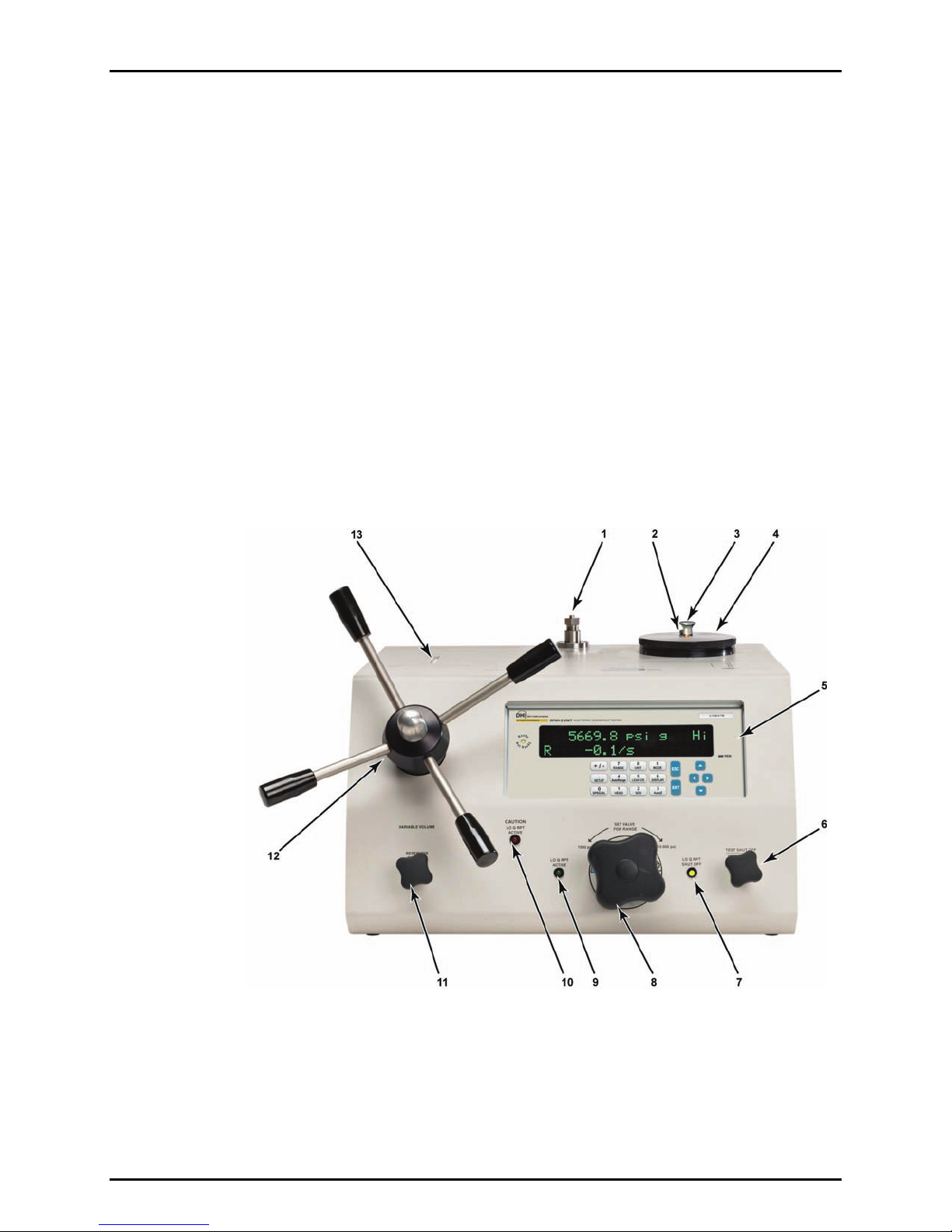
1.3.1.1 FRONT VIEW
1. TEST port (DH500F)
2. Reservoir cap vent valve
3. Priming pump
4. Reservoir cap
5. Reference pressure monitor (RPM4-E-DWT)
6. Test shut off valve and fine pressure adjustment
7 ‘Lo Q-RPT shut off’ valve position prompt LED
8. Lo Q-RPT shut off valve
9. ‘Lo Q-RPT active’ valve position prompt LED
10.‘Lo Q-RPT active’ caution indicator
11. Reservoir shut off valve
12. Variable volume (pressure generation)
13. Variable volume piston position indicator
Figure 1. E-DWT-10000-AF front view

1. INTRODUCTION
Page 5 © 2008 DH Instruments, a Fluke Company
1.3.1.2 REAR VIEW
1. Reservoir cap
2. Priming pump
3. Reservoir cap vent valve
4. TEST connection (DH500 F) 5. Power connection (12 VDC)
6. Footswitch (remote [ENT]) connection
(footswitch not included)
Figure 2. E-DWT-10000-AF rear view
1.3.2 RPM4-E-DWT REFERENCE PRESSURE MONITOR VIEWS
1.3.2.1 FRONT PANEL
1. Pressure ready/not ready indicator
2. 2 x 20 vacuum fluorescent display
3. Remote activity indicator
4. Cursor control keys
5. Multi-function keypad
Figure 3. RPM4-E-DWT reference pressure monitor front panel
E-DWT-10000-AF OPERATION AND MAINTENANCE MANUAL
© 2008 DH Instruments, a Fluke Company Page 6
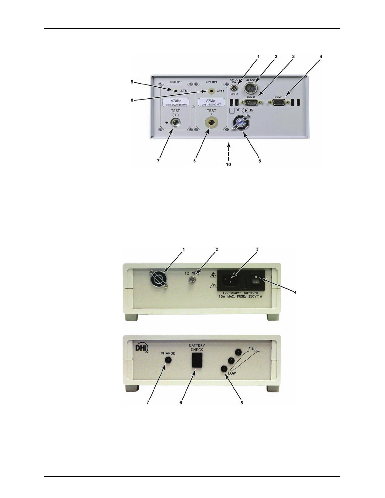
1.3.2.2 REAR PANEL
1. 12VDC power supply connection
2. Accessories connector (to E-DWT rear
panel FOOTSWITCH and LEDs)
3. COM2 connector
4. COM1 connector
5. Fan
6. TEST(+) pressure port, Lo Q-RPT
7. TEST(+) pressure port, Hi Q-RPT
8. ATM pressure port, Lo Q-RPT
9. ATM pressure port, Hi Q-RPT
10. Product label (bottom of case)
Figure 4. RPM4-E-DWT reference pressure monitor rear panel
1.3.3 BATTERY/CHARGER PACK VIEWS
1. Cooling fan
2. 12VDC output connector (to E-DWT)
3. IEC power connection
4. ON/OFF switch (ON – battery connected to charger;
OFF - battery connected to 12 VDC output/E-DWT)
5. Charge level indicator
6. Charge level check switch
7. Battery charging indicator (green –
charging; green flashing – fully charged.
Figure 5. Battery/charger pack front and rear E-DWT-10000-AF dimensions

1. INTRODUCTION
Page 7 © 2008 DH Instruments, a Fluke Company
1.3.4 E-DWT-10000-AF DIMENSIONS
Figure 6. E-DWT-10000-AF dimensions
1.3.5 E-DWT-10000-AF HYDRAULIC SCHEMATIC
1. TEST port
2. System pressure rupture disc
3. Reservoir
4. Reservoir vent valve
5. Priming pump
6. Test shut off and fine adjustment valve
7. Lo Q-RPT shut off valve
8. Lo Q-RPT pressure relief valve
9. Reservoir shut off valve
10. Variable volume
11. Lo Q-RPT (ref pressure transducer)
12. Hi Q-RPT (ref pressure transducer)
Figure 7. E-DWT-10000-AF hydraulic schematic

E-DWT-10000-AF OPERATION AND MAINTENANCE MANUAL
© 2008 DH Instruments, a Fluke Company Page 8
N
NO
OT
TE
ES
S

2. INSTALLATION
Page 9 © 2008 DH Instruments, a Fluke Company
2
2.
.
I
IN
NS
ST
TA
AL
LL
LA
AT
TI
IO
ON
N
2.1 UNPACKING AND INSPECTION
2.1.1 REMOVING FROM PACKAGING
E-DWT-10000-AF complete with accessories is delivered in a reusable, molded plastic
shipping container with polyurethane inserts to hold it in place.
Remove the E-DWT-10000-AF and its accessories from the shipping container and remove
each element from its protective plastic bag.
Retain the shipping container for repacking the E-DWT to take it into the field or to ship it
for recalibration or repair.
2.1.2 INSPECTING CONTENTS
Check that all items are present and have no visible damage. If damage is noted, report it to
your Receiving Department for appropriate action.
A new E-DWT-10000-AF includes all items listed in Table 1.
Table 1. E-DWT-10000-AF packing list
DESCRIPTION PART NO.
E-DWT-10000-AF electronic deadweight tester 3322392
ACCESSORIES: 3338865
1 ea. Transport case (with inserts) (used for original
shipment) 3329777
2 ea. Battery/charger pack 3338787
1 ea. Battery/charger pack to E-DWT power cable 3335937
2 ea. Power cord (7.5 ft) 3133781
1 ea. 12 VDC power supply pack 3335610
4 ea. Handle, variable volume 3329907
1 ea. DH500 M x 1/4 in. NPT F adaptor 3335561
1 ea. DH500 M x 1/8 in. NPT F adaptor 3142684
1 ea. E-DWT-10000-AF Documentation Disk including:
•E-DWT-10000-AF Operation and Maintenance
Manual, p/n 550166
3338256
1 ea. Calibration Report 3152121
1 ea. Test Report (included only if the E-DWT-10000-AF
is delivered under AFMETCAL contract FY2333-07-
M-0025)
3338793
1 ea. General Accessories Disk 3139043

E-DWT-10000-AF OPERATION AND MAINTENANCE MANUAL
© 2008 DH Instruments, a Fluke Company Page 10
2.2 SITE REQUIREMENTS
Install E-DWT-10000-AF on a flat, stable surface at a convenient height. If using the battery/charger
pack, consider its placement.
When used with its battery/charger pack, E-DWT-10000-AF requires no external support facilities. If not
using the battery, an electrical power source of 100 to 240VAC, 50-60 Hz is required.
2.3 SETUP
2.3.1 PREPARING FOR OPERATION
To prepare E-DWT-10000-AF for check out and operation:
Remove the protective plastic sheet from the front panel display.
Familiarize yourself briefly with the E-DWT front and real panels and controls (see
Section 1.3.1).
Connect the 12 VDC power supply pack to a source of 100 to 240V, 50-60 Hz AC power
and to the 12 VDC connection on the rear of the E-DWT; or, use the battery/charger pack
and cable if battery has been charged (see Section 3.3).
Connecting power causes the RPM4-E-DWT to power up.
Observe the front panel display as the RPM4-E-DWT initializes, error checks and goes to
the MAIN RUN screen (see Section 3.6.1). If the RPM4-E-DWT fails to reach the main
run screen, service is required. Record the sequence of operations and displays
observed and contact a DHI Authorized Service Provider (see Section 1, Table 25).
Check that one of the two green Valve Status LEDs on the front of the E-DWT is lit (the
red LED should NOT be ON). If neither of the green LEDs lights, check that the 12 pin
circular connector on the rear panel of the RPM4-E-DWT itself is properly connected to
the J1 ACC. connector.
Install the four variable volume handles into the variable volume hub on the front of the E-DWT.
Leave the stainless steel plug in the top surface TEST port. Check that the gland holding
the plug is tight.
Check/Set Security Level
RPM4-E-DWT has a security system based on user levels. By default, the security
system is set to “low”, which includes access restriction to internal calibration coefficients,
and there is no password required to change the security level. See Section 3.9.5.5 for
information on the security level system. As part of the RPM4-E-DWT startup, determine
the security level that is appropriate for the RPM4-E-DWT and set a password if desired.
RPM4-E-DWT is delivered with the security level set to “low” to avoid inadvertent altering of
critical internal settings but with access to changing security levels unrestricted. It is recommended
that the low security level be maintained at all times and password protection be implemented if
control over setting of security levels is desired.
2.3.2 SETTING UP AUTOTEST FILES
E-DWT’s RPM4-E-DWT supports automated test/calibration sequences. AutoTest sequence
parameters for testing specific DUTs can be stored in File AutoTest files and recalled to run a
test. Consider setting up File AutoTest files for frequently tested DUTs as part of the E-DWT
set up process (see Section 3.1.3).
Table of contents
Other DH Instruments Test Equipment manuals


