Dhollandia DH-AR Series User manual

Order ref: MD027.EN Doc: USE_CE operation manual DHAR_EUR EN_2020 Rev: 0Date: MARCH 25, 2020
Manufacturer:
DHOLLANDIA N.V. Zoomstraat 9 9160 LOKEREN (Belgium)
Tel : +32 (0)9 349 06 92 Fax : +32 (0)9 349 09 77
website : www.dhollandia.com
Read the manual in its entirety before operating the hydraulic ramp
Keep this manual in the vehicle cab, as reference for the driver and hydraulic ramp operator
edition
DH-AR*
hydraulic ramps
*
OPERATION
MANUAL

1
DHOLLANDIA
TABLE OF CONTENTS
1UNDERSTANDING SAFETY AND WARNING SIGNS..................................................................................................................2
2CONTACT INFORMATION AND DISCLAIMERS..........................................................................................................................3
3GENERAL INTRODUCTION .........................................................................................................................................................4
4INTENDED USE ............................................................................................................................................................................4
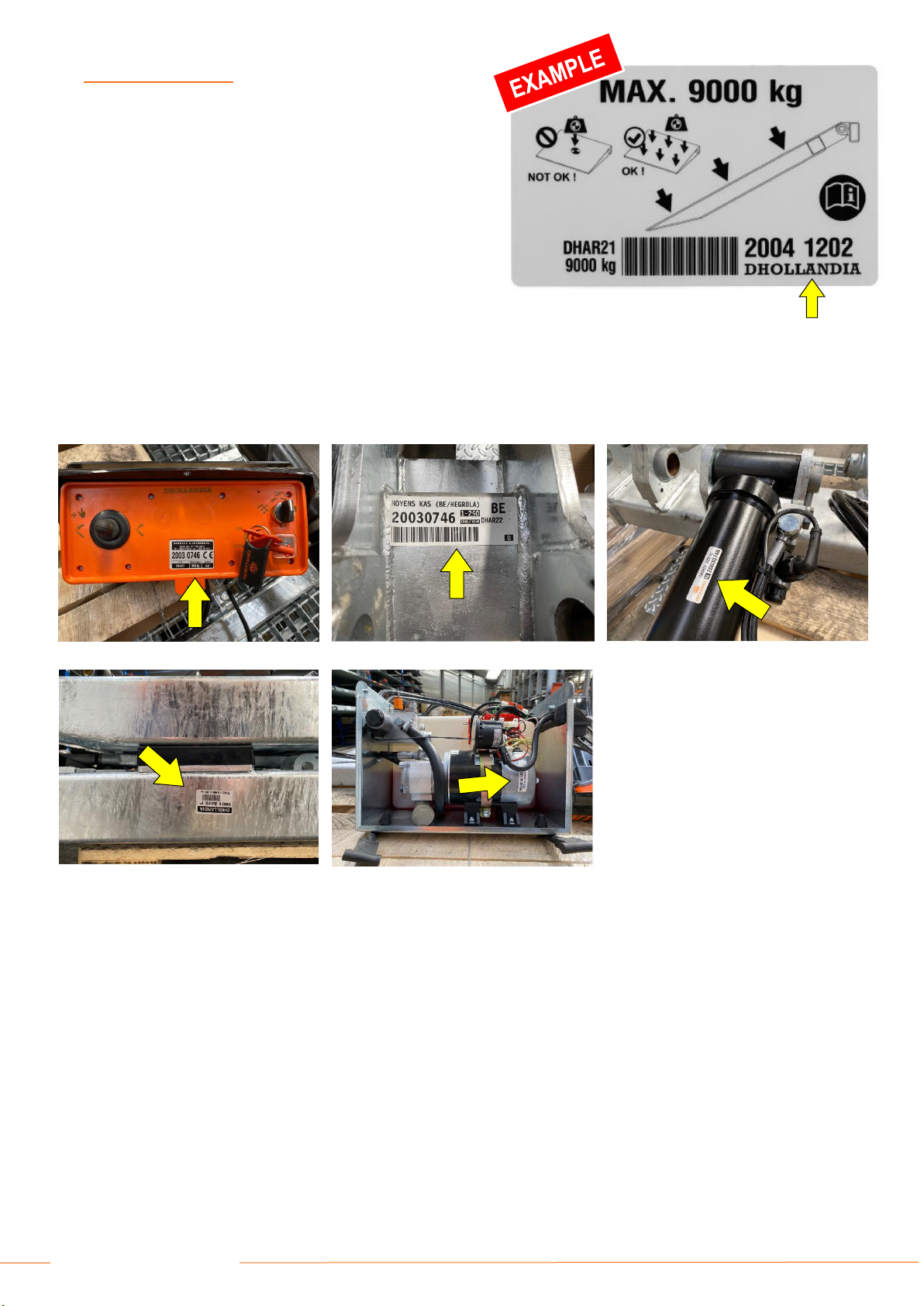
5IDENTIFICATION...........................................................................................................................................................................5
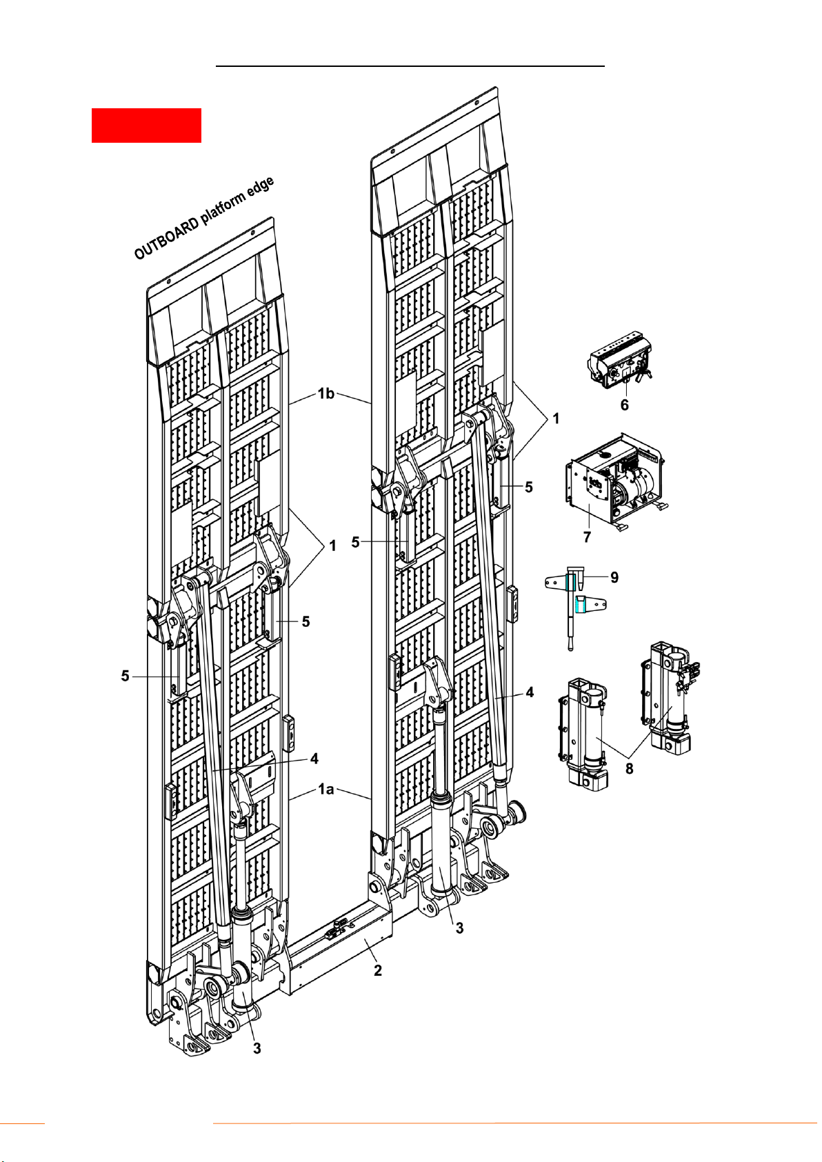
6DESCRIPTION AND HYDRAULIC RAMP TERMINOLOGY .........................................................................................................6
6.1 General .................................................................................................................................................................................6
6.2 Safety devices.....................................................................................................................................................................14
7SAFETY INSTRUCTIONS FOR USING THE HYDRAULIC RAMP .............................................................................................17
7.1 DO NOT use hydraulic ramp without adequate safety and operator training ......................................................................17
7.2 General safety instructions..................................................................................................................................................17
7.3 Danger zones, risk of crush and shear injury ......................................................................................................................21
7.4 Safe operator position .........................................................................................................................................................23
7.5 Recommended daily pre-trip inspection..............................................................................................................................24
7.6 Importance of preventative maintenance ............................................................................................................................25
8LOAD CHARTS AND CORRECT LOADING PROCEDURES.....................................................................................................26
8.1 General ...............................................................................................................................................................................26
8.2 Instructions for working at loading docks ............................................................................................................................27
9OPERATING INSTRUCTIONS - PRINCIPLES AND PROCEDURES.........................................................................................28
9.1 General ...............................................................................................................................................................................28
9.2 Switching the main power on / off .......................................................................................................................................28
9.3 Operating instructions for DH-AR1* ramps..........................................................................................................................29
9.4 Operating instructions for DH-AR2* ramps..........................................................................................................................32
9.5 Operating instructions for DH-AR3* / AR4* ramps .............................................................................................................35
9.6 The use of hydraulic side-shift [option OAH803] .................................................................................................................40
9.7 The use of hydraulic stabilising legs....................................................................................................................................41
10 DECALS.......................................................................................................................................................................................42
11 MEANING OF SAFETY AND WARNING SIGNS ........................................................................................................................43
12 END NOTE ..................................................................................................................................................................................45

2
DHOLLANDIA
1UNDERSTANDING SAFETYAND WARNING SIGNS
Many safety signs and symbols used in this manual are based on international standards, others refer to specific situations or actions.
Consult section 11 on page 43 for an overview of signs and symbols used in DHOLLANDIA manuals, and their meaning.
Please take special notice of the following signs used in the manual. They indicate the likelihood and severity of a potential injury if a
person fails to follow the instructions presented on the safety sign.
DANGER: indicates an imminently hazardous situation which, if not avoided, will result in death or
serious injury. [white letters on red background]
WARNING: indicates a potentially hazardous situation which, if not avoided, could result in death
or serious injury. [black letters on orange background]
CAUTION: indicates a potentially hazardous situation which, if not avoided, could result in minor
or moderate injury. [black letters on yellow background]
NOTICE: is used to address practices not related to physical injury. [white letters on blue
background]
SAFETY INSTRUCTIONS: indicate general instructions relative to safe work practices, reminders
of proper safety procedures, or the location of safety equipment. [white letters on green
background]
SAFETY ALERT SYMBOL: is used to alert the user to potential hazards. All safety messages that
accompany this sign shall be obeyed to avoid possible harm. [free-standing, or on back-ground
colours red, orange, yellow or black]
WARNING
Failure to understand and to follow the instructions in this manual can put the operator and any bystanders at great risk of
serious bodily injury and death.
Prior to operating the hydraulic ramp, make sure you understand the safety and warning signs used, and read them in
conjunction with the instructions in this manual.
If in doubt, DO NOT operate the hydraulic ramp. Contact your national DHOLLANDIA distributor. See page 3 for contact info.
NOTICE
SAFETY
INSTRUCTIONS

3
DHOLLANDIA
2CONTACT INFORMATION AND DISCLAIMERS
DHOLLANDIA hydraulic ramps are regularly being adapted to new vehicle and chassis developments, and specialized customer
requirements. Therefore, DHOLLANDIA reserves the right to alter product specifications without prior notice; and potentially
modifications or new developments might not have been taken into account at the time of printing.
NOTICE
Please confirm you have reviewed the most up-to-date version of this manual prior to operation of the associated DHOLLANDIA
hydraulic ramp. See below for instructions to download the latest version of the manual.
Contact your national DHOLLANDIA distributor if you have any questions regarding the installation, operation, repair and
maintenance of DHOLLANDIA hydraulic ramps, to obtain replacement copies of manuals or decals, or to learn about available
equipment options for DHOLLANDIA hydraulic ramps.
If in doubt where to find your national DHOLLANDIA distributor, visit the official DHOLLANDIA website:
www.dhollandia.com → Country & language selection → Distributors & service
The latest version of all manuals can also be downloaded from the DHOLLANDIA website:
www.dhollandia.com → Country & language selection → Downloads → Operation manuals →
… select required manual
LANGUAGE: in virtue of the low sales quantity and custom-made character of these hydraulic ramps, the equipment is delivered
to the client with an English operation manual. Other languages are available in pdf format via the link mentioned above.
Take notice of following important disclaimers:
DISCLAIMERS
DHOLLANDIA disclaims liability for any personal injury, death, or property damage that results from operating a hydraulic
ramp that has been modified from the original design, without explicit written approval from the manufacturer.
DHOLLANDIA disclaims liability for any personal injury, death, or property damage that results from use of aftermarket or
non-OEM replacement parts for service or repair of the hydraulic ramp.
DHOLLANDIA disclaims liability for any personal injury, death, or property damage that results from improper use of the
hydraulic ramp.
DHOLLANDIA disclaims liability for any personal injury, death, or property damage that results from overloading or improperly
loading the platform, disregard of the maximum rated lift capacity and the applicable load charts.
There are no warranties, express or implied, including the warranty of merchantability or a warranty of fitness for a particular
purpose extending beyond that set forth in this manual.

4
DHOLLANDIA
3GENERAL INTRODUCTION
This OPERATION MANUAL explains how the DHOLLANDIA hydraulic ramp is manufactured; what safety devices are
incorporated in its design; and how to use the hydraulic ramp in a correct manner, that preserves the integrity of the machine over
the intended lifetime and helps maximize the safety of the operator and any bystanders.
The MAINTENANCE AND REPAIR MANUAL (separate) explains how to maintain and service the hydraulic ramp in the
appropriate manner, maximizing the safety of the operator and any bystanders, and ensuring the reliability of the hydraulic ramp
over the intended lifetime.
The CE IDENTIFICATION AND INSPECTION LOGBOOK (separate) contains the serial number identification, the CE Declaration
of Conformity, the Fitting Declaration to be filled out by the installer of the hydraulic ramp, and an overview of the owner’s legal
obligations in terms of periodic testing and certification.
The manuals must be kept with the hydraulic ramp at all times, as a reference book for the operators and technical service
personnel.
4INTENDED USE
DHOLLANDIA hydraulic ramps are designed to be fitted to commercial vehicles (commercial trucks, trailers and semi-trailers), and
shall be used exclusively to load and unload the goods transported on the vehicle they are fitted to, within the limits of the load chart,
in compliance with the operator instructions and safety instructions described in this manual.
Except for model DH-AR4*, which is also suitable for the use at loading docks, DHOLLANDIA hydraulic ramps should be used
exclusively to transfer wheeled equipment or machinery from the ground to the vehicle floor or vice versa. This means the platform, its
outboard platform edge and mechanical support legs and hydraulic stabilising legs MUST be in firm contact with the ground.
WARNING
Improper use of the hydraulic ramp will put the operator and other parties at great risk of serious bodily injury and death.
Therefore, the use of the hydraulic ramp is restricted to skilled operators only; who have been properly trained, and who know
and understand the full contents of this manual.
Unauthorized modifications to the hydraulic ramp can put the operator and other parties at great risk of serious bodily injury
and death. Therefore, it is strictly forbidden to modify the hydraulic ramp and its safety devices in any way.
Use of aftermarket or non-OEM replacement parts to repair or maintain the hydraulic ramp is strictly prohibited and may result
in serious bodily injury or death to the operator or any bystanders.
WARNING
Improper use of the hydraulic ramp will put the operator and bystanders at great risk of serious bodily injury and death.
Therefore, it is strictly forbidden to use the hydraulic ramp in a different way, or for different purposes than described in the
operation manual.
The hydraulic ramp must NEVER be used as an elevated work platform, to push loads, or to carry people.
DHOLLANDIA disclaims liability for any personal injury and / or property damage that results from improper use.

5
DHOLLANDIA
5IDENTIFICATION
Every DHOLLANDIA hydraulic ramp is identified by and
labelled with a unique 8-digit serial number (with or without
a space between the first and last 4 digits). Use this number
for any inquiry on a particular hydraulic ramp, or when ordering
replacement parts.
In addition to the hydraulic ramp type and serial number, the
various serial number labels provide additional information,
such as: the maximum rated lift capacity and load chart, the
date of manufacture, etc...
These labels are usually affixed to the vehicle body and
various hydraulic ramp components, and can be found in
following locations (the yellow arrows point to the serial
numbers):
On the main external control box
On the lift frame
On the tilt cylinders
On the platform
On the pump unit
Affixed to the side of the vehicle body, or on the platform

6
DHOLLANDIA
6DESCRIPTION AND HYDRAULIC RAMP TERMINOLOGY
6.1 GENERAL
DHOLLANDIA hydraulic ramps are developed and manufactured using state-of-the-art technology, high quality materials and
components and highly skilled workmanship. They comply with the European CE safety regulations mentioned in the Declaration
of Conformity issued with each lift (unless agreed otherwise for hydraulic ramps exported outside of CE region).
The DH-AR* series comprises of a range of hydraulic ramps, designed for a wide variety of trucks, trailers and semi-trailers, and
is available with lift capacities ranging from 3,000 to 20,000 kg.
In its travel position, the platform of the hydraulic ramp is stowed vertically behind the vehicle body. Before use, the platform is
tilted open from the vertical travel position, to rested position at the ground.
Main details and terminology: see below
DH-AR1*●NON-ARTICULATED HYDRAULIC RAMP ●TERMINOLOGY
See figure below for parts corresponding to numbers in this table
The DH-AR1* are basic ramps with a non-articulated platform.
#
Description
1
Platform: carries the load during loading / unloading. In standard execution, it is manufactured from closed steel sheet with
a non-slip working surface. Main options include: air-permeable platforms with a steel mesh surface (up to max. 3,000 kg)
or heavy-duty steel grids (all capacities); and platforms prepared for wood flooring.
Seen in width, the platform can stretch out over the full width of the vehicle (type DH-AR11) or be split in 2 separate sections
with an empty space in between (type DH-AR12).
2
Ramp frame: mounted in a fixed position at the rear cross member of the vehicle body. It bears the platform and the
hydraulic tilt cylinders.
3
Tilt cylinders L+R: 2 hydraulic cylinders used to OPEN / CLOSE the platform
4
Main external control box: mounted in a fixed position at the side of the vehicle, under the body. Contains the electrical
switches allowing the operator to execute all hydraulic ramp functions STABILISING LEGS DOWN / OPEN / CLOSE /
STABILISING LEGS UP.
5
Hydraulic pump unit: contains the electric motor driving the hydraulic pump, the oil tank, and the control valves.
6
Hydraulic stabilising legs: stabilising legs mounted vertically at the vehicle chassis or body, used to support the chassis
of the vehicle while loading and unloading. [see also section 9.7 from page 41 onwards]

7
DHOLLANDIA
DH-AR1* ●NON-ARTICULATED HYDRAULIC RAMP ●TERMINOLOGY
INBOARD
platform edge
EXAMPLE

8
DHOLLANDIA
DH-AR2*●FOLDABLE HYDRAULIC RAMP ●TERMINOLOGY
See figure below for parts corresponding to numbers in this table
The DH-AR2* are ramps with a longer, foldable platform. The platform main section and the foldable point are linked by 2 fixed
stabilisers, so that they OPEN / CLOSE in a synchronized way, as a pair.
#
Description
1
Platform: carries the load during loading / unloading. In standard execution, it is manufactured from closed steel sheet with
a non-slip working surface. Main options include: air-permeable platforms with a steel mesh surface (up to max. 3,000 kg)
or heavy-duty steel grids (all capacities); and platforms prepared for wooden flooring.
The platform consists of a platform main section and a foldable point. Seen in width, the platform can stretch out over the
full width of the vehicle (type DH-AR21) or be split in 2 separate sections with an empty space in between (type DH-AR.22).
1a
Platform main section: bottom or inboard section of the foldable platform, opened / closed by the hydraulic tilt cylinders
mounted on the ramp frame.
1b
Foldable point: top or outboard section of the foldable platform, opened / closed automatically by the fixed stabilisers
mounted between the 2 platform sections.
2
Ramp frame: mounted in a fixed position at the rear cross member of the vehicle body. It bears the platform and the
hydraulic tilt cylinders.
3
Tilt cylinders L+R: 2 hydraulic cylinders used to OPEN / CLOSE the platform.
4
Fixed stabilisers: fixed rods between the platform main section and the foldable point, used to automatically unfold or fold
the foldable point while the platform main section is hydraulically opened / closed.
5
Mechanical support legs: mechanical legs to support the articulation between the 2 platform sections, when the platform
is rested at the ground.
The support legs form integral part of the strength of the platform, and MUST be set in firm contact with solid ground before
the platform is loaded..
6
Main external control box: mounted in a fixed position at the side of the vehicle, under the body. Contains the electrical
switches allowing the operator to execute all hydraulic ramp functions STABILISING LEGS DOWN / OPEN / CLOSE /
STABILISING LEGS UP.
7
Hydraulic pump unit: contains the electric motor driving the hydraulic pump, the oil tank, and the control valves.
8
Hydraulic stabilising legs: stabilising legs mounted vertically at the vehicle chassis or body, used to support the chassis
of the vehicle while loading and unloading. [see also section 9.7 from page 41 onwards]
9
Platform fold lock (on foldable platforms): optional mechanical lock to hold the 2 folding sections together while the
hydraulic ramp is stowed in its travel position.
Other types of locking devices, fitted by the installer, are possible, for example chain binders or ratchet straps between the
foldable point and the vehicle body.

9
DHOLLANDIA
DH-AR2* ●FOLDABLE HYDRAULIC RAMP ●TERMINOLOGY
INBOARD
platform edge
EXAMPLE

10
DHOLLANDIA
DH-AR3… / AR4… ●FOLDABLE HYDRAULIC RAMP ●TERMINOLOGY
See figure below for parts corresponding to numbers in this table
The DH-AR3* are ramps with a longer, foldable platform. The platform main section and the foldable point are linked by 2 additional
tilt cylinders, so that they OPEN / CLOSE independently.
The DH-AR4* are a special execution of the DH-AR3*, adapted to be used as a bridge at the loading dock.
#
Description
1
Platform: carries the load during loading / unloading. In standard execution, it is manufactured from closed steel sheet with
a non-slip working surface. Main options include: air-permeable platforms with a steel mesh surface (up to max. 3,000 kg)
or heavy-duty steel grids (all capacities); and platforms prepared for wooden flooring.
The platform consists of a platform main section and a foldable point. Seen in width, the platform can stretch out over the
full width of the vehicle (type DH-AR31 / AR41) or be split in 2 separate sections with an empty space in between (type DH-
AR32 / AR42).
1a
Platform main section: bottom or inboard section of the foldable platform, opened / closed by the hydraulic tilt cylinders
mounted on the ramp frame.
1b
Foldable point: top or outboard section of the foldable platform, opened / closed automatically by the fixed stabilisers
mounted between the 2 platform sections.
2
Ramp frame: mounted in a fixed position at the rear cross member of the vehicle body. It bears the platform and the
hydraulic tilt cylinders.
3
Tilt cylinders L+R: 2 hydraulic cylinders used to OPEN / CLOSE the platform main section.
4
Tilt-cylinders L+R: 2 hydraulic cylinders used to STRETCH OUT / FOLD BACK the foldable point.
5
Mechanical support legs: mechanical legs to support the articulation between the 2 platform sections, when the platform
is rested at the ground.
The support legs form integral part of the strength of the platform, and MUST be set in firm contact with solid ground before
the platform is loaded..
6
Main external control box: mounted in a fixed position at the side of the vehicle, under the body. Contains the electrical
switches allowing the operator to execute all hydraulic ramp functions STABILISING LEGS DOWN / OPEN / CLOSE /
STABILISING LEGS UP.
7
Hydraulic pump unit: contains the electric motor driving the hydraulic pump, the oil tank, and the control valves.
8
Hydraulic stabilising legs: stabilising legs mounted vertically at the vehicle chassis or body, used to support the chassis
of the vehicle while loading and unloading. [see also section 9.7 from page 41 onwards]
9
Platform fold lock (on foldable platforms): optional mechanical lock to hold the 2 folding sections together while the
hydraulic ramp is stowed in its travel position.
Other types of locking devices, fitted by the installer, are possible, for example chain binders or ratchet straps between the
foldable point and the vehicle body.

11
DHOLLANDIA
DH-AR3* / AR4* ●FOLDABLE HYDRAULIC RAMP ●TERMINOLOGY
INBOARD
platform edge
EXAMPLE

12
DHOLLANDIA
DH-AR12 + OAH803 ●SIDE-SHIFT ●TERMINOLOGY
See figure below for parts corresponding to numbers in this table
The optional side shift [ref. OAH803] is illustrated here on the basis of a DH-AR12 non-articulated hydraulic ramp, but is available
on all types DH-AR22 / AR32 / AR42 with a platform split into 2 separate sections.
#
Description
1
Platform: carries the load during loading / unloading. In standard execution, it is manufactured from closed steel sheet with
a non-slip working surface. Main options include: air-permeable platforms with a steel mesh surface (up to max. 3,000 kg)
or heavy-duty steel grids (all capacities); and platforms prepared for wooden flooring.
The platform is split in 2 separate sections with an empty space in between.
2
Ramp frame: mounted in a fixed position at the rear cross member of the vehicle body. It bears the platform and the
hydraulic tilt cylinders, and incorporates the sliding mechanism for the side shift function.
2a
Side-shift cylinder: hydraulic cylinder mounted horizontally in the ramp frame, used to slide either of the 2 or both platform
sections towards the center or in opposite direction towards the sides of the vehicle floor.
2b
Slide lock: mechanical lock mounted on the L+R platform sections, used to secure either of the 2 platform sections in the
desired position by means of intrusion of the slide lock pin into a lock rail.
2c
Lock rail: rail mounted behind the side-shift cylinder, provided with subsequent holes where the slide lock can slot into, so
that the platform section gets secured in the desired position.
3
Tilt cylinders L+R: 2 hydraulic cylinders used to OPEN / CLOSE the platform
4a
Main external control box: mounted in a fixed position at the side of the vehicle, under the body. Contains the electrical
switches allowing the operator to execute all hydraulic ramp functions STABILISING LEGS DOWN / OPEN / CLOSE /
STABILISING LEGS UP.
4b
Side-shift control: wander lead with a spiral cable, used to side-shift either of the platform sections towards the left or right.
5
Hydraulic pump unit: contains the electric motor driving the hydraulic pump, the oil tank, and the control valves.
6
Hydraulic stabilising legs: stabilising legs mounted vertically at the vehicle chassis or body, used to support the chassis
of the vehicle while loading and unloading. [see also section 9.7 from page 41 onwards]

13
DHOLLANDIA
DH-AR12 + OAH803 ●SIDE-SHIFT ●TERMINOLOGY
INBOARD
platform edge
EXAMPLE

14
DHOLLANDIA
6.2 SAFETY DEVICES
DHOLLANDIA hydraulic ramps are equipped with multiple safety devices in order to ensure that goods can be loaded and unloaded
with maximum safety for the operator, any incidental bystanders, and the load itself. The following safety devices are incorporated or
recommended on most hydraulic ramps:
Electrical safety valves mounted on all cylinders [standard]. The safety
valves lock the oil inside the hydraulic cylinders as long as they are not
energized via the electrical controls. The purpose is to secure the platform
in its travel position while driving, or in any other fixed position, in case of
accidental failure of a hydraulic pipe (as soon as the electrical controls are
released).
DHOLLANDIA safety valves are equipped with a manual emergency control,
allowing the operator or repair agent to open the valve manually in case of
electrical failure (see MAINTENANCE AND REPAIR MANUAL).
Platform fold lock [optional]. The foldable point of foldable ramps DH-AR2*
can partially swing open and shut when driving on uneven roads.
DHOLLANDIA strongly recommends such kind of lock to:
reduce driving noise
reduce the wear of the articulation pins and bearings in the articulation
between the 2 platform sections.
The foldable point of foldable ramps DH-AR3* / AR4* should be pressurized
by means of the control box when closing it up in travel position. It is still
good practice to add a locking device, to prevent a platform fall in case of
accidental loss of hydraulic pressure.
NOTICE
In order to maximize the longevity of articulation pins and bearings, it is important that the platform is pressurized and firmly
secured in its travel position.
In case of full height bodies: if the platform can be closed and pressurized against the rear frame of the body, no further
measures besides a platform fold lock are required.
In case of flat-bed or drop-side bodies: fixed or demountable stanchions MUST be foreseen at the rear of the vehicle floor,
against which the platform can be pressurized. DHOLLANDIA strongly recommends to use chain binders, ratchet straps or
similar solutions to pull the rearmost platform section against the stanchions, and pressurize the platform in a safe travel
position in this way. Examples:

15
DHOLLANDIA
Pressure relief valve [standard]. Safety device integrated into the pump unit, protecting the hydraulic circuit and components
against excessive pressure while CLOSING the platform.
Pressure compensating flow valves [standard]. Flow valves are integrated
in the hydraulic circuits to ensure the platform opens at a safe speed under
all foreseeable circumstances of normal use.
Hydraulic stabilising legs [optional]. Stabilising legs can be mounted at the
vehicle chassis or body, to support the chassis of the vehicle and protect the
platform of the ramp while loading and unloading. [see also section 9.7 from
page 41 onwards].
The use of stabilising legs is mandatory on certain vehicles, Consult the
Fitting and Body Building Instructions of the vehicle manufacturer and make
sure you comply.
Mechanical support legs [standard]. On foldable platforms, mechanical legs
are used to support the articulation between the 2 platform halves, when the
platform is rested at the ground. They MUST be set in firm contact with solid
ground before loading the platform.
Overload relief system [standard]. The platform should only be loaded when
the outboard platform edge and the mechanical support legs (if applicable)
are in firm contact with the ground.
This system automatically opens the safety valves on the hydraulic cylinders
and drops the platform down to the ground if it is loaded without being fully
deployed as described above.
2-hand external control box [standard]. On the external control box
mounted in fixed position at the side of the vehicle body, all functions are
actuated by means of a control switch and a safety switch. The compulsory
use of 2 hands to actuate the various lift functions, protects the operator from
crushing his / her head, limbs or upper body between the CLOSING platform
and the rear frame of the vehicle body.
Hydraulic ramp on/off switch [min. 1 compulsory]. Depending on
configuration, the electrical power to the hydraulic ramp is switched on / off
by means of:
1. A cabin switch (provided by the truck manufacturer or DHOLLANDIA
[option OAE503.1]). This switch enables the operator to switch the
control power to the main external control box on / off.

16
DHOLLANDIA
2. A main battery disconnect switch integrated in the external control
box [optional]. This switch enables the operator to switch the main
battery power to the hydraulic ramp on / off. If available, the operator
MUST switch off the main battery disconnect switch after each use of
the hydraulic ramp.
3. A combination of both
Fuses [standard]. A 15A fuse for the electrical control circuit comes mounted in the pump unit and in the main external control
box (for most types). A 150 –250A fuse for the electrical main battery circuit is supplied by the truck manufacturer or by
DHOLLANDIA. Both fuses protect the electrical circuits against short-circuits and amperage peaks.
Decals [standard]. The hydraulic ramps are supplied with a number of
operation deals, load diagrams and safety decals, most of them to be
applied to the vehicle body during installation. These decals must
always be kept clean and legible and replaced whenever required.

17
DHOLLANDIA
7SAFETY INSTRUCTIONS FOR USING THE HYDRAULIC RAMP
7.1 DO NOT USE HYDRAULIC RAMP WITHOUT ADEQUATE SAFETY AND OPERATOR TRAINING
DHOLLANDIA hydraulic ramps shall be exclusively used to load and unload the goods transported on the carrying vehicle, within
the limits of the applicable load chart, and in compliance with the operator instructions and safety instructions in this manual.
The operator should follow all other policies and procedures applicable to the job situation including health & safety regulations,
road and traffic regulations, as well as company procedures. The operator should not use the hydraulic ramp if he/she cannot use
it in accordance with all applicable regulations and instructions.
The operator must be at least 18 years of age.
7.2 GENERAL SAFETY INSTRUCTIONS
WARNING
To avoid serious bodily injury or death, the operator must use appropriate work clothes. NEVER wear loose-fitting clothes that
may be trapped in the moving parts of the hydraulic ramp. ALWAYS wear professional safety-toe shoes, protective gloves,
and eye protection. Use of hardhat is recommended.
Slipping (and falling) can result in serious bodily injury and death. To prevent injury by slipping:
oALWAYS wear professional safety-toe shoes with a good non-slip sole.
oDO NOT use the hydraulic ramp if it is covered with snow, mud, dirt, debris, liquids or other substances.
oDO NOT run on or off the platform.
Tripping (and falling) can result in serious bodily injury and death. To prevent injury by tripping:
oNEVER leave the hydraulic ramp unattended in partially open position.
oPay attention to protruding items on the platform surface at all times (ex. platform lights, wheel blocks,
other foreign objects, etc.).
oDO NOT run on or off the platform.
Falling from the platform can result in serious bodily injury and death. To prevent injury by falling:
oMake sure your footing is solid. DO NOT run on or off the platform.
oNEVER move the vehicle while a person is standing on the platform or inside the vehicle body.
oNEVER use the platform as an elevated working platform.
WARNING
Improper use of the hydraulic ramp will put the operator and other parties at great risk of serious bodily injury and death.
To reduce the risk of serious bodily injury to the operator and any bystanders, the use of the hydraulic ramp is restricted to
skilled operators, who have been properly trained, and who know and understand the full contents of this manual.
To reduce the risk of serious bodily injury or death, THE OPERATOR MUST COMPLY WITH ALL SAFETY INSTRUCTIONS
AND WARNING LABELS IN THIS SECTION AND THE ENTIRE MANUAL before and while operating the hydraulic ramp.

18
DHOLLANDIA
WARNING
Prior to operating the hydraulic ramp, the vehicle must be safely parked on level and solid ground, the parking brake applied,
and the engine must be switched off. Lock open the rear doors and secure all other moving parts of the vehicle body. Failure
to abide by these instructions can result in serious bodily injury or death to the operator or bystanders.
Prior to releasing the mechanical platform lock (if so equipped) and using the hydraulic ramp, check if the hydraulic ramp can
be used safely. Take precautions to ensure your own safety, and the safety of bystanders or other parties in traffic. Clear the
working area of any objects that could potentially impede movement of the hydraulic ramp. Failure to abide by these instructions
can result in serious bodily injury or death to the operator or bystanders.
Ensure that the vehicle cannot become unstable when
putting heavy weight on the platform. If the vehicle or the
hydraulic ramp are equipped with hydraulic stabilising legs,
deploy these before opening the platform. Ensure that the
stabilising legs are positioned on solid even ground.
In case of soft terrain (sand, gravel,…), solid support blocks
MUST be used under the stabilising legs. Failure to abide
by these instructions can result in serious bodily injury or
death to the operator or bystanders. Lock the air suspension
of the vehicle, so that the vehicle floor cannot rise after
deployment of the stabilising legs.
If the vehicle or hydraulic ramp are not equipped with
stabilising legs, and if the operating instructions of the
vehicle manufacturer allow so, lower the vehicle air
suspension, and lock it in this position.
The purpose of this is to ALWAYS keep the floor height of
the vehicle unchanged while loading / unloading, prevent
potential overloading and material damage to the hydraulic
ramp or vehicle chassis.
ALWAYS make sure that the outboard platform edge and the mechanical support legs under the platform fully rest on solid
even ground before loading the platform. In case of soft terrain [sand, gravel, etc.) ALSWAYS use solid support blocks to
support and stabilise.

19
DHOLLANDIA
WARNING
ALWAYS make sure you have sufficient free space to load / unload and maneuver the load safely. ALWAYS make sure a
safety distance X. is kept between the back of the vehicle and the following vehicle or nearest obstacle.
To reduce the risk of serious bodily injury or death of the operator
and third parties in traffic, ALWAYS make sure the platform is
clearly visible to other persons from all approach directions.
DHOLLANDIA recommends the use of 4 warning cones, placed
around the work area of the platform.
When the hydraulic ramp is operated near vehicular traffic, wear
working clothes in high-visibility colors and a high-visibility safety
vest.
To reduce the risk of serious bodily injury or death, make sure the
working zone is sufficiently lighted.
Inspect the hydraulic ramp prior to each use. If any unsafe condition exists or unusual noises or movements are noticed, DO
NOT use the hydraulic ramp and contact an authorized DHOLLANDIA service agent for repair. Please see ‘pre-trip inspection’
procedures from 7.5 page 24 onwards.
Read and comply with all warning decals, pictograms and instructions affixed to the hydraulic ramp. Failure to abide by warnings
and instructions may result in serious bodily injury or death.
The hydraulic ramp must not be used if the operator is intoxicated, impaired or distracted in any way. NEVER use a phone or
mobile device when operating the hydraulic ramp.
The hydraulic ramp shall be used by means of original control units only. Operating the hydraulic ramp with unauthorized control
units will increase risk of serious bodily injury or death to the operator or any bystanders.
Limit the operation of the hydraulic ramp to one single operator. Operation of the hydraulic ramp by more than one operator at
a time may cause confusion and increase the risk of serious bodily injury or death.
This manual suits for next models
8
Table of contents
Other Dhollandia Lifting Column manuals