Dhollandia DH-VO Series User manual

Doc: FIT_VO_US_EN_2020_rev0 Rev: 0Date: JANUARY 1, 2020
Manufacturer:
DHOLLANDIA US, L.L.C.
270 Southridge Parkway
Bessemer City North Carolina, 28016
website : www.dhollandia.com
DH-VO* column liftgates
INSTALLATION MANUAL
Read the manual in its entirety before operating the liftgate
Keep this manual in the vehicle cab, as reference for the driver and liftgate operator
** Pictured: VO.K1
with hydraulic tilt

1
DHOLLANDIA
Contents
1UNDERSTANDING SAFETY AND WARNING SIGNS........................................................................................................................ 2
2INTRODUCTION AND DISCLAIMERS ............................................................................................................................................... 3
3CONTACT INFORMATION ................................................................................................................................................................. 4
4SAFETY PRECAUTIONS FOR OPERATION ..................................................................................................................................... 5
5SAFETY PRECAUTIONS FOR INSTALLATION................................................................................................................................. 5
6LIFTGATE TERMINOLOGY ................................................................................................................................................................ 8
6.1 Getting started........................................................................................................................................................................... 18
6.2 Installation dimensions.............................................................................................................................................................. 19
7DIMENSIONS OF VEHICLE.............................................................................................................................................................. 20
7.1 Clearance Dimensions .............................................................................................................................................................. 21
8MOUNTING OF THE LIFT FRAME (premounted platform)............................................................................................................... 23
8.1 Positioning the liftgate ............................................................................................................................................................... 24
8.2 Welding of the liftframe.............................................................................................................................................................. 26
9INSTALLATION OF CONTROL SWITCH.......................................................................................................................................... 29
9.1 Wiring for additional controls..................................................................................................................................................... 30
10 CONNECTION TO THE BATTERIES................................................................................................................................................ 33
11 PUTTING THE LIFTGATE INTO SERVICE....................................................................................................................................... 35
12 LUBRICATION INSTRUCTIONS....................................................................................................................................................... 36
13 COMMISIONING & QUALITY CONTROL ......................................................................................................................................... 36
14 DECALS ............................................................................................................................................................................................ 38
14.1 Regular decals .......................................................................................................................................................................... 38
14.2 Use of the ‘WARNING. LIFTGATE OUT OF SERVICE. DO NOT ATTEMPT TO OPERATE’ sign .......................................... 42
14.3 Identification decals................................................................................................................................................................... 43
15 APPENDIX......................................................................................................................................................................................... 44
15.1 APPENDIX 1 - Important signs ................................................................................................................................................. 44
15.2 APPENDIX 2 - Prescribed torques values for bolts supplied with liftgate.................................................................................. 46
15.3 APPENDIX 3 - PDI checklist 1/2 ............................................................................................................................................... 48
15.4 APPENDIX 4 - Safe operator position on the platform.............................................................................................................. 51
15.5 APPENDIX 5 - Circuit breaker................................................................................................................................................... 53
15.6 APPENDIX 6 - Cab cut off switch.............................................................................................................................................. 54
15.7 APPENDIX 7 - Electric and hydraulic Information..................................................................................................................... 55
15.8 APPENDIX 8 - End note............................................................................................................................................................ 57

2
DHOLLANDIA
1UNDERSTANDING SAFETYAND WARNING SIGNS
Many safety signs and symbols used in this manual are based on international standards, others refer to specific situations or
actions.
Consult Appendix 1 for an overview of signs and symbols used in DHOLLANDIA manuals, and their meaning. Make sure you
understand these signs and symbols prior to starting the installation.
Examples of standard ANSI
signs
Examples of DHOLLANDIA
purpose made signs
Please take special notice of the following signs used in the manual. They indicate the likelihood and severity of a potential injury if a
person fails to follow the instructions presented on the safety sign.
NOTICE
DANGER: indicates an imminently hazardous situation which, if not avoided, will result in death or serious
injury. [white letters on red background]
WARNING: indicates a potentially hazardous situation which, if not avoided, could result in death or
serious injury. [black letters on orange background]
CAUTION: indicates a potentially hazardous situation which, if not avoided, could result in minor or
moderate injury. [black letters on yellow background]
NOTICE: is used to address practices not related to physical injury. [white letters on blue background]
SAFETY INSTRUCTIONS: indicate general instructions relative to safe work practices, reminders of
proper safety procedures, or the location of safety equipment. [white letters on green background]
SAFETY
INSTRUCTIONS
SAFETY ALERT SYMBOL: is used to alert the user to potential hazards. All safety messages that
accompany this sign shall be obeyed to avoid possible harm. [free-standing, or on back-ground colours
red, orange, yellow or black]

3
DHOLLANDIA
WARNING
Failure to understand and to follow the instructions in this manual can put the operator and any bystanders at great risk of serious
bodily injury and death.
Prior to operating the liftgate, make sure you understand the safety and warning signs used, and read them in conjunction with the
instructions in this manual.
If in doubt, DO NOT operate the liftgate. Contact your national DHOLLANDIA distributor. See page 4 for contact info.
2INTRODUCTION AND DISCLAIMERS
This manual provides you with the information necessary for the installation of the DHOLLANDIA DH-VO column liftgate.
It provides you with general instructions applicable to the common truck and trailer types. It might be possible that specific issues
particular to your installation case are not adequately covered by this manual. If in doubt, please contact your local DHOLLANDIA
distributor for further assistance.
DHOLLANDIA liftgates are regularly being adapted to new vehicle and chassis developments, and specialized customer requirements.
Therefore, DHOLLANDIA reserves the right to alter product specifications without prior notice. Such modifications might not have been
included at the time this manual was printed.
NOTICE
Please confirm you have reviewed the most up-to-date version of this manual prior to installation and operation of the associated
DHOLLANDIA liftgate.
It is the sole responsibility of the installer(s) to follow shop best practices for safety and craftsmanship and to use good common
sense.
Contact your national DHOLLANDIA distributor if you have any questions regarding the installation, operation, repair and maintenance
of DHOLLANDIA liftgates, or to obtain replacement copies of manuals or decals.
WARNING
Improper installation can cause damage to the liftgate, can reduce the durability and reliability of the liftgate, and can put the operator
and bystanders at great risk of serious bodily injury and death in many ways.
It is therefore essential that the liftgates are installed with proper care, in compliance with the installation instructions of this manual.
In case of doubt, ALWAYS contact the national DHOLLANDIA distributor for further advice, prior to continuing.

4
DHOLLANDIA
3CONTACT INFORMATION
DHOLLANDIA liftgates are regularly being adapted to new vehicle and chassis developments, and specialized customer requirements.
Therefore, DHOLLANDIA reserves the right to alter product specifications without prior notice; and potentially modifications or new
developments might not have been taken into account at the time of printing
NOTICE
Please confirm you have reviewed the most up-to-date version of this manual prior to operation of the associated DHOLLANDIA liftgate.
See below for instructions to download the latest version of the manual.
Contact your national DHOLLANDIA distributor if you have any questions regarding the installation, operation, repair and maintenance of
DHOLLANDIA liftgates, to obtain replacement copies of manuals or decals, or to learn about available equipment options for DHOLLANDIA
liftgates.
Take notice of following important disclaimers:
DISCLAIMERS
DHOLLANDIA disclaims liability for any personal injury, death, or property damage that results from operating a liftgate that has
been modified from the original design, without explicit written approval from the manufacturer.
DHOLLANDIA disclaims liability for any personal injury, death, or property damage that results from use of aftermarket or non-
OEM replacement parts for service or repair of the liftgate.
DHOLLANDIA disclaims liability for any personal injury, death, or property damage that results from improper use of the liftgate.
DHOLLANDIA disclaims liability for any personal injury, death, or property damage that results from overloading or improperly
loading the platform, disregard of the maximum rated lift capacity and the applicable load charts.
There are no warranties, express or implied, including the warranty of merchantability or a warranty of fitness for a particular purpose
extending beyond that set forth in this manual.
DHOLLANDIA US, LLC
United States - West
12968 Santa Ana Avenue
Fontana CA 92337
Tel: 855-856-8225
Sales.USA@dhollandia.com
The latest version of all manuals can also be downloaded from the DHOLLANDIA website
www.dhollandia.com → Downloads → User’s manuals → … select required manual
DHOLLANDIA US, LLC
United States - East
200 Hilton Street West
Easton PA 18042
Tel: 855-894-1188
Sales.USA@dhollandia.com
DHOLLANDIA CANADA, Inc.
Canada
2105 Boulevard des Entreprises
Terrebonne Quebec J6Y1W9
Tel: 888-750-5438
Sales.CANADA@dhollandia.com
DHOLLANDIA MEXICO, Inc.
Mexico
Fraccionamiento Industrial
Dinamo del Norte,
Calle Tierra 103-105
C.P. 65500, Salinas Victoria,
Monterrey- Nuevo Leon
Tel: +52 81 13340968
Sales.MEXICO@dhollandia.com

5
DHOLLANDIA
4SAFETY PRECAUTIONS FOR OPERATION
It is essential that the personnel involved in installing, servicing and repairing liftgates knows, understands and applies
the safety instructions and precautions contained in the OPERATION MANUAL issued with the liftgate.
Therefore, make sure you consult the OPERATION MANUAL prior to installing or operating the liftgate.
5SAFETY PRECAUTIONS FOR INSTALLATION
It is essential that the personnel involved in installing, servicing and repairing liftgates knows, understands and applies
the safety instructions and precautions contained in the GENERAL SAFETY INSTRUCTIONS FOR INSTALLATION,
MAINTENANCE AND REPAIR manual.
Therefore, make sure you consult the GENERAL SAFETY INSTRUCTIONS FOR INSTALLATION, MAINTENANCE
AND REPAIR manual prior to installing the liftgate.
These instructions are supplied as a separate manual with your liftgate.
You can also contact the national DHOLLANDIA distributor for the latest edition of this manual. See page 4 for contact
info. Or download the latest edition from the website:
www.dhollandia.com →your language →Downloads →User’s manuals → General information
WARNING
Improper use of the liftgate will put the operator and other parties at great risk of serious bodily injury and death.
To reduce the risk of serious bodily injury to the operator and any bystanders, the use of the liftgate is restricted to skilled operators,
who have been properly trained, and who know and understand the full contents of the operation manual.
To reduce the risk of serious bodily injury or death, THE OPERATOR MUST COMPLY WITH ALL SAFETY INSTRUCTIONS AND
WARNING LABELS IN THE OPERATION MANUAL before and while operating the liftgate.
Please confirm you have reviewed the most up-to-date version of this manual prior to installation and operation of the associated
DHOLLANDIA liftgate.

6
DHOLLANDIA
WARNING
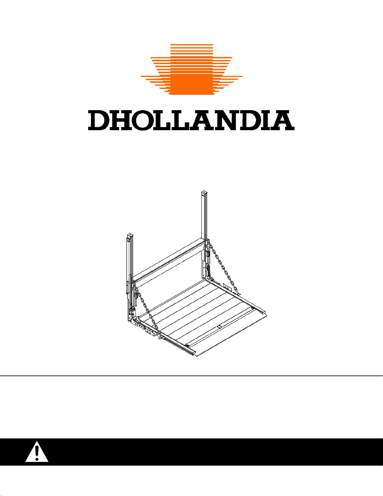
The personnel involved in liftgate installation are exposed to various dangers. Improper use of the liftgate, or ignorance and neglect
during installation, will put the personnel at great risk of bodily injury and death.
Improper installation can cause damage to the liftgate, can reduce the durability and reliability of the liftgate, and can put the operator
and bystanders at great risk of serious bodily injury and death in many ways.
To reduce the risk of serious bodily injury or death to the installation personnel, to the operator, and any bystanders, liftgate
installation works MUST be restricted to skilled and trained technicians, who have been duly and professionally trained, and know,
understand and apply the manuals of the liftgate:
1. OPERATION MANUAL
2. INSTALLATION MANUAL
3. GENERAL SAFETY INSTRUCTIONS FOR INSTALLATION, MAINTENANCE AND REPAIR
ALWAYS confirm you have reviewed the most up-to-date version of these manuals prior to installation and operation of the
associated DHOLLANDIA liftgate.
In case of doubt, ALWAYS contact the national DHOLLANDIA distributor for further advice, prior to continuing.
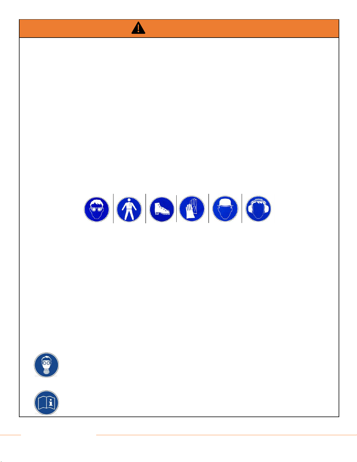
ALWAYS wear appropriate Personal Protective Equipment. This includes but may not be limited to: ANSI rated glasses with side
guards, or a wrap-around face shield; steel toe safety shoes; fire-resistant overalls; protective gloves; adequate ear protection; a
safety helmet when working under the vehicle chassis.
NEVER wear loose-fitting clothes that may get trapped in the moving parts of the liftgate, or in any machinery and tools used for the
installation. Don’t wear rings, bracelets, necklaces, watches etc…
ALWAYS use the proper tool for the job. Repair or replace worn or damaged tools before use.
Pay special attention to the lifting devices (forklifts, overhead cranes, hoists, chains or ropes…) used to handle the liftgates, and for
the clamping tools (C-clamps, pipe clamps, vise grips…) used to clamp the liftgate, its mounting plates and floor extension to the
vehicle chassis and box. Ensure these tools are appropriate for the job, and in good working order.
Place the vehicle on a flat even ground and chock the wheels so that it cannot move during the installation process. In case of a
motor vehicle, make sure the engine is off and the parking brake is set before starting.
Do not work underneath the liftgate, or within reach of the platform and the moving parts of the liftgate, without properly securing
and supporting the platform and the liftgate frame against accidental falling. Use an overhead crane and hoists, a forklift or equivalent
means to secure the heavy liftgate components.
Make sure the vehicle battery power is disconnected while installing the liftgate. Connect the battery power to the liftgate only when
the installation is completed, or as required in the installation instructions.
Before welding, note that welding on galvanized parts releases hazardous fumes. Provide adequate ventilation,
and wear an appropriate toxic fume rated welding respirator.
NEVER modify DHOLLANDIA liftgates or their mounting plates without prior written consent by the manufacturer.
If for any reason, trouble-shooting and / or repair might be needed during the installation process, consult and
follow the guidelines and safety instructions of the MAINTENANCE MANUAL.

7
DHOLLANDIA
NOTICE
Make sure the vehicle battery power is disconnected while installing the liftgate. Connect the battery power to the liftgate only when
the installation is completed, or as required in the installation instructions.
Except for the support channels and bracing of the side steps, which are usually welded to the cross members of the auxiliary
chassis, DHOLLANDIA liftgates are designed as a bolt-on system, and don’t require any welding. See Appendix 2 for
prescribed torque values.
Welding should be done by qualified personnel only, and only to the extent allowed by the vehicle manufacturer. Ensure that the
positive and ground cables are disconnected from the batteries, and that all vehicle electrical and electronic equipment is fully
isolated before welding.
ALWAYS keep the ground clamp as close as possible to the weld location.
WARNING
NEVER modify DHOLLANDIA liftgates or their mounting plates, NEVER deviate from the described installation procedures without prior
written consent by the manufacturer.

8
DHOLLANDIA
6LIFTGATE TERMINOLOGY
DHOLLANDIA liftgates are developed and manufactured using state-of-the-art technology, high quality materials and components and
highly skilled workmanship.
The DH-VOU.K1, DH-VOL.K1, DH-VOM.K1 and DH-VOH.K1 comprise of a range of column liftgates, designed for a wide variety of
trucks, trailers and semi-trailers, and are available with lift capacities ranging from 1,000 to 4,400lbs.
In its travel position, the platform of the column liftgate is stowed vertically behind the vehicle body. Before use, the platform is lowered
approx. 7”, then tilted open 90 degrees from the vertical travel position, to a horizontal work position.
Depending on liftgate model and options chosen, the opening and closing of the platform can be manual, or driven by 1 or 2 hydraulic
tilt cylinders. See table below:
Type
Lift capacity
Manual closure
Hydraulic closure 0-90°
OVH004
Hydraulic closure with adjustable
platform pitch
OVH011
DH-VOU.K1
1,100 - 1,650 lbs
standard
not available
not available
DH-VOL.K1
1,650 - 2,200 lbs
standard
optional
not available
DH-VOM.K1
2,200 - 3,300 lbs
standard
optional
optional
DH-VOH.K9
3,300 - 4,400 lbs
standard
optional
optional

9
DHOLLANDIA
DH-VOU.K1 ● MANUAL CLOSURE ● LIFTGATE TERMINOLOGY
See figure below for parts corresponding to numbers in this table
#
Description
1
Lift columns: set of 2 columns mounted in a fixed position against the vehicle body. These form the rails within which the lift
runners carrying the platform travel up and down.
2
Cylinder beam: horizontal beam mounted at the vehicle floor. This beam contains the lift cylinder; the drive system consisting
of chains and pulleys; and often also the hydraulic pump unit.
3
Lift cylinder: hydraulic cylinder used to LOWER / LIFT the lift runners, the platform and its load.
4
Hydraulic pump unit: contains the electric motor driving the hydraulic pump, the oil tank, and the control valves. The unit can
be premounted inside the cylinder beam (if technical parameters allow so), or is mounted separately on the vehicle chassis.
5
Platform: carries the load during lifting and lowering. Manufactured from steel or light-weight aluminium and with a non-slip
working surface. In standard execution, the platform is equipped with a fixed leading edge. Optional cart-stops in the platform
surface, or a retention ramp at the outboard platform edge, are available as an option.
6
Torsion bar(s): powerful spring device hidden inside the platform, assisting with the manual OPEN / CLOSE of the platform (in
case of manual closure)
7
Lift runners: set of 2 slides carrying the platform, travelling up and down in the lift columns. They are lifted and lowered by the
lift cylinder and the drive mechanism (chains and pulleys).
8
Stow lock: hook mounted on the off-side lift column, preventing the platform from falling open when it is stowed in its travel
position.
9
Platform lock: pivoting lock on the near-side lift runner with dual function:
1. Platform in vertical position: the hook holds the platform closed against the lift runners. Release the platform lock to open the
platform.
2. Platform in horizontal position: the lock blocks the platform in work position, and prevents the torsion bar(s) from tilting up the
platform. Release the platform lock to close the platform.
10
Main external control box: mounted in a fixed position at the side of the vehicle or under the body. It contains the electrical
switches to LOWER / LIFT the platform.
11
Center point of maximum load: point up to which the maximum rated capacity of the liftgate is valid. Beyond that point, the
maximum safe working load diminishes according to the applicable load charts found at Section 8 of this manual.

10
DHOLLANDIA
DH-VOU.K1 ● MANUAL CLOSURE ● LIFTGATE TERMINOLOGY
1
1
2
3
4
5
6
7
7
8
9
11
10
9

11
DHOLLANDIA
DH-VOL.K1 / DH-VOM.K1 ● MANUAL CLOSURE ● LIFTGATE TERMINOLOGY
See figure below for parts corresponding to numbers in this table
#
Description
1
Lift columns: set of 2 columns mounted in a fixed position against the vehicle body. These form the rails within which the lift
runners carrying the platform travel up and down.
2
Cylinder beam: horizontal beam mounted at the vehicle floor. This beam contains the lift cylinder; the drive system consisting
of chains and pulleys; and often also the hydraulic pump unit.
3
Lift cylinder: hydraulic cylinder used to LOWER / LIFT the lift runners, the platform and its load.
4
Hydraulic pump unit: contains the electric motor driving the hydraulic pump, the oil tank, and the control valves. The unit is
mounted separately on the vehicle chassis.
5
Platform: carries the load during lifting and lowering. Manufactured from steel or light-weight aluminium and with a non-slip
working surface. In standard execution, the platform is equipped with a fixed leading edge. Optional cart-stops in the platform
surface, or a retention ramp at the outboard platform edge, are available as an option.
6
Torsion bar(s): powerful spring device hidden inside the platform, assisting with the manual OPEN / CLOSE of the platform (in
case of manual closure)
7
Lift runners: set of 2 slides carrying the platform, travelling up and down in the lift columns. They are lifted and lowered by the
lift cylinder and the drive mechanism (chains and pulleys).
8
Stow lock: set of 2 lock plates mounted on left and right side at the inboard platform edge. To stow the platform in its travel
position, CLOSE the platform from the open work position to the vertical position. Then LIFT the vertical platform against the
underside of the cylinder beam until you hear the hydraulic system turn in over-pressure.
9
Platform lock: up and down sliding lock on the near-side lift runner with dual function:
1. Platform in vertical position: the lock holds the platform closed against the lift runners. Release the platform lock to open the
platform.
2. Platform in horizontal position: the lock blocks the platform in work position, and prevents the torsion bar(s) from tilting up the
platform. Release the platform lock to close the platform.
10
Main external control box: mounted in a fixed position at the side of the vehicle or under the body. It contains the electrical
switches to LOWER / LIFT the platform.
11
Center point of maximum load: point up to which the maximum rated capacity of the liftgate is valid. Beyond that point, the
maximum safe working load diminishes according to the applicable load charts found at Section 8 of this manual.

12
DHOLLANDIA
DH-VOL.K1 / DH-VOM.K1 ● MANUAL CLOSURE ● LIFTGATE TERMINOLOGY
1
1
2
3
4
5
6
7
7
8
8
8
8
8
9
9
10
11

13
DHOLLANDIA
DH-VOL.K1 / DH-VOM.K1 ● HYDRAULIC CLOSURE REF. OVH004 ● LIFTGATE TERMINOLOGY
See figure below for parts corresponding to numbers in this table
#
Description
1
Lift columns: set of 2 columns mounted in a fixed position against the vehicle body. These form the rails within which the lift
runners carrying the platform travel up and down.
2
Cylinder beam: horizontal beam mounted at the vehicle floor. This beam contains the lift cylinder; the drive system consisting
of chains and pulleys; and often also the hydraulic pump unit.
3
Lift cylinder: hydraulic cylinder used to LOWER / LIFT the lift runners, the platform and its load.
4
Hydraulic pump unit: contains the electric motor driving the hydraulic pump, the oil tank, and the control valves. The unit is
mounted separately on the vehicle chassis.
5
Platform: carries the load during lifting and lowering. Manufactured from steel or light-weight aluminium and with a non-slip
working surface. In standard execution, the platform is equipped with a fixed leading edge. Optional cart-stops in the platform
surface, or a retention ramp at the outboard platform edge, are available as an option.
6
Torsion bar(s): powerful spring device hidden inside the platform, assisting with the manual OPEN / CLOSE of the platform (in
case of manual closure)
7
Lift runners: set of 2 slides carrying the platform, travelling up and down in the lift columns. They are lifted and lowered by the
lift cylinder and the drive mechanism (chains and pulleys).
8
Stow lock: set of 2 lock plates mounted on left and right side at the inboard platform edge. To stow the platform in its travel
position, CLOSE the platform from the open work position to the vertical position. Then LIFT the vertical platform against the
underside of the cylinder beam until you hear the hydraulic system turn in over-pressure.
9
Tilt cylinder: optional hydraulic cylinder used to OPEN / CLOSE the platform. The option OVH004 offers hydraulic instead of
manual OPEN / CLOSE, but does not offer adjustable platform orientation.
10
Main external control box: mounted in a fixed position at the side of the vehicle or under the body. It contains the electrical
switches to OPEN / LOWER / LIFT / CLOSE the platform.
11
Center point of maximum load: point up to which the maximum rated capacity of the liftgate is valid. Beyond that point, the
maximum safe working load diminishes according to the applicable load charts found at Section 8 of this manual.

14
DHOLLANDIA
DH-VOL.K1 / DH-VOM.K1 ● HYDRAULIC CLOSURE REF. OVH004 ● LIFTGATE TERMINOLOGY
10
1
1
2
3
4
5
6
7
7
8
8
9
11
8
9
8
8

15
DHOLLANDIA
DH-VOH.K9 ● HYDRAULIC CLOSURE REF. OVH011 ● LIFTGATE TERMINOLOGY
See figure below for parts corresponding to numbers in this table
#
Description
1
Lift columns: set of 2 columns mounted in a fixed position against the vehicle body. These form the rails within which the lift
runners carrying the platform travel up and down.
2
Cylinder beam: horizontal beam mounted at the vehicle floor. This beam contains the lift cylinder; the drive system consisting
of chains and pulleys; and often also the hydraulic pump unit.
3
Lift cylinder: hydraulic cylinder used to LOWER / LIFT the lift runners, the platform and its load.
4
Hydraulic pump unit: contains the electric motor driving the hydraulic pump, the oil tank, and the control valves. The unit is
mounted separately on the vehicle chassis.
5
Platform / Foldable platform (optional): carries the load during lifting and lowering. Manufactured from steel or light-weight
aluminium and with a non-slip working surface. In standard execution, the platform is equipped with a fixed leading edge. Optional
cart-stops in the platform surface, or a retention ramp at the outboard platform edge, are available as an option.
5a
Platform main section: inboard section of the (optional) foldable platform. Manufactured from steel, with a non-slip working
surface.
5b
Flip-over point: foldable outboard section of the (optional) foldable platform. Manufactured from steel or light-weight aluminium,
with a non-slip working surface.
6
Lift runners: set of 2 slides carrying the platform, travelling up and down in the lift columns. They are lifted and lowered by the
lift cylinder and the drive mechanism (chains and pulleys).
7
Stow lock: set of 2 lock plates mounted on left and right side at the inboard platform edge. To stow the platform in its travel
position, CLOSE the platform from the open work position to the vertical position. Then LIFT the vertical platform against the
underside of the cylinder beam until you hear the hydraulic system turn in over-pressure.
8
Tilt cylinders: optional hydraulic cylinders (option OVH011) used to OPEN / CLOSE the platform, or to TILT DOWN / TILT UP
the platform, and adjust its pitch to the slope of the ground.
9
Main external control box: mounted in a fixed position at the side of the vehicle or under the body. It contains the electrical
switches to OPEN / LOWER / LIFT / CLOSE the platform.
10
Center point of maximum load: point up to which the maximum rated capacity of the liftgate is valid. Beyond that point, the
maximum safe working load diminishes according to the applicable load charts found at Section 8 of this manual.

16
DHOLLANDIA
DH-VOH.K9 ● HYDRAULIC CLOSURE REF. OVH011 ● LIFTGATE TERMINOLOGY
10
9
1
1
2
4
3
5
5a
5b
6
6
7
7
6
8
8
8
7
7

17
DHOLLANDIA
DH-VOU.K1 / DH-VOL.K1 / DH-VOM.K1 ● LOAD RESTRAINTS ● LIFTGATE TERMINOLOGY
See figure below page for parts corresponding to numbers in this table
#
Description
1
Platform: carries the load during lifting and lowering. Manufactured from steel or light-weight aluminium and with a non-slip
working surface. In standard execution, the platform is equipped with a fixed leading edge. Optional cart-stops in the platform
surface, or a retention ramp at the outboard platform edge, are available as an option.
2
Cart-stops: usually 2 load restraint flaps mounted in or just in front of the fixed leading edge of the platform. Depending on
options chosen, the cart-stops feature a manual or an automatic operation (see also 9.9 from page 44 onwards), and are actuated
by springs.
3
Rear or outboard retention ramps: 1 full-width or 2 partial width load restraints ramps mounted at the outboard platform edge.
In travel position, the ramps lie folded back on the platform surface. When travelling up and down, the ramps can be raised and
blocked in vertical position to prevent rolling cargo on the platform from falling off. At the ground, the ramps can be deployed as
an access ramp to drive cargo on and off the platform. (See also 9.9)
4
Side retention ramps: 2 load restraints ramps mounted at the side edges of the platform. In travel position, the ramps lie folded
back on the platform surface. When travelling up and down, the ramps can be raised and blocked in vertical position to prevent
rolling cargo on the platform from falling off. At the ground, the ramps can be deployed as an access ramp to drive cargo on and
off the platform. (See also 9.9)
1
2
1
3
4
4

18
DHOLLANDIA
6.1 GETTING STARTED
OEM Vehicle manufacturers may have issued important instructions on various aspects of the liftgate installation, specific to the brand
and type of chassis, such as welding instructions (or prohibition to weld!); instructions on chassis drilling and bolt-on connections to
the chassis; recommendations on the use of hydraulic stabilizing legs; guidelines for the battery and ground cable connections; fuses
and other electrical interfaces; etc...
NOTICE
The installer MUST verify and ensure compatibility between the liftgate and the vehicle.
The installer MUST verify and ensure compliance with the installation instructions issued by the vehicle and body
manufacturer.
Improper modifications to the vehicle chassis or body could cause serious mechanical failure of the vehicle. The installer MUST
ensure that modifications to the vehicle chassis and / or body will not adversely affect the structural integrity of the chassis and / or
body.
In the event instructions of vehicle manufacturer conflict with the installation instructions issued by DHOLLANDIA (e.g. on fuse
ratings, etc.), contact your national DHOLLANDIA distributor for further assistance.
In the event OEM instructions conflict with the installation instructions issued by DHOLLANDIA (e.g. fuse ratings, etc.) contact
DHOLLANDIA see page 4 for contact info.
Place vehicle on a flat even ground and chock the wheels so that it cannot move during the installation process. In case of a motor
vehicle, switch off the engine and engage the parking brake before starting.
Verify the installation kit is complete, and that all parts needed to correctly fit the liftgate are present.
Compare the voltage of the vehicle batteries with the voltage of the hydraulic pump unit of the liftgate.
Compare the installation dimensions and maximum installation parameters indicated in the installation drawing with the actual
dimensions of the vehicle, to verify compliance. (See next chapter).
Verify if the vehicle chassis and body are strong enough to support the load and moment created by the liftgate at maximum rated
capacity. Refer to the Body Builder Guidelines of the OEM vehicle manufacturer for details.
Check the stability of the vehicle and the weight over the axles with the addition of a liftgate loaded to maximum capacity. The weights
indicated in the technical documentation and price list are theoretical and approximate and may vary from one liftgate installation to
another.
Make sure that the body is accurately fitted to the vehicle chassis.
Remove all objects that are mounted in the mounting space required by the liftgate (RUP, spare wheel carrier, pallet racks, tool boxes,
etc.). If necessary, consult with the OEM vehicle manufacturer for replacement solutions (e.g. special spare wheel carriers, exhaust
pipe modifications, etc.).
Finish the liftgate in compliance with applicable road legislation of the country where the vehicle will be registered.
When connecting hydraulic fittings, make sure that the connections are thoroughly clean, and that you don’t contaminate the hydraulic
oil.
Grease all bearings and pins before putting the liftgate into service. It is recommended to grease all articulation bearings before
mounting the corresponding articulation pin.

19
DHOLLANDIA
After installation, work through the pre-delivery inspection (PDI) checklist, verify all check points with due diligence. Make sure the
final inspection is signed off by an inspector who is not part of the installation team.
Do not pressurize any liftgate functions (LIFT / LOWER) before the liftgate installation is fully finished.
During installation and while testing, verify that the liftgate and its moving parts don’t interfere with, or cause damage to the vehicle
systems (e.g. to suspension, braking system, hydraulic and electrical circuits, etc.).
6.2 INSTALLATION DIMENSIONS
Before starting the installation, verify if the actual floor height VFH of the vehicle falls within the given min. and max. range VFH MIN
< VFH < VFH MAX.
The max. floor height VFH MAX. should be measured for an UNLOADED vehicle (= worst case)
The min. floor height VFH MIN. should be measured for a FULLY LOADED vehicle (= worst case)
NOTICE
Where chassis beams, longs sills, the rear sill and other steel chassis or body components have been cut, grinded, drilled, etc…, the
installer should apply adequate anti-corrosive coating to protect the vehicle and body against corrosion. Check, and make sure you
comply with the instructions of the OEM vehicle manufacturer.
Other manuals for DH-VO Series
1
This manual suits for next models
7
Table of contents
Other Dhollandia Lifting Column manuals
Popular Lifting Column manuals by other brands

AA4C
AA4C AA-2PFP45 user manual

Ravaglioli
Ravaglioli KPH370.70LIKTU Translation of the original instructions

Linak
Linak DESKLINE DL20 user manual

Ravaglioli
Ravaglioli RAV241VS1402 manual

Hettich
Hettich LegaMove Installation and operating instructions

APlusLift
APlusLift HW-10KBP-A Installation & operation manual