DHR DHR60 LED User manual

TECHNICAL MANUAL
DHR60 LED
MED2014/90/EU
46 CFR 111.75-17
Signalling Lights
Searchlights
Whistles
Den Haan Rotterdam
S
i
n
c
e
1
9
2
2
Navigation Lights
2Version 3.1 May 2018
Den Haan Rotterdam
DISCLAIMER
Despite constant care and attention DHR puts in its manuals it is still possible that information in this
manual is incomplete or incorrect.
We do not guarantee that the information in the manual is suitable for the purpose for which the
information was consulted. All information is offered in the state in which it actually is and without any
(implicit) guarantee or warranty regarding its validity or its suitability for a particular purpose or otherwise.
All illustrations are for illustrative purposes only. This manual is not intended to cover every possible detail
about the product.
We exclude all liability for any damages, direct or indirect, of any nature whatsoever, arising from or in any
way connected with the use of this manual. In addition we are not liable for damages, direct or indirect,
arising from the use of information obtained from this manual.
A user of this manual may not publish copyright protected works or other information from the manual
or in any way reproduce the information without our permission. This also includes the reproduction of
information or parts thereof by publication in an electronic (computer) network.

3Version 3.1 May 2018
Den Haan Rotterdam
TABLE OF CONTENTS
Technical data 4
Product photos 5
Dimensions 6
Available models 7
Exploded view 8
Repair kit 8
Electrical specification 9
Electrical spec. Manoeuvring light 10
Lifetime control 10
Positioning lights 11
Positioning all-round light 12
Mounting instructions 13
4Version 3.1 May 2018
Den Haan Rotterdam
TECHNICAL DATA
Application
• For all vessels used in (European) inland navigation
• For all seagoing vessels with a length less than 50 meters
• UL1104 (USA): for vessels of 65 feet or more in length
In compliance with:
• Directive 2014/90/EU
• Regulation (EU) 2017/306 Annex A.1/6.1
• US Code of Federal Regulations Title 46 CFR 111.75-17
Conform standards:
• COLREG Annex l/14
• IMO Resolution A.694 (17)
• IMO Resolution MSC.253 (83)
Materials:
• Housing: Seawater resistant aluminium, hard anodised, matt black
• LED driver: epoxy potted
• Screen: Seawater resistant aluminium, hard anodised
• Lens: Borosilicate glass
Min. visibility:
Sector lights All-round
Starboard - bright 2 NM White - bright 2 NM Green - bright 2 NM
Port - bright 2 NM Manoeuvring 5 NM Yellow - bright 2 NM
Masthead - bright 5 NM Red - bright 2 NM Blue - normal 1 NM
Stern - bright 2 NM Red & White 2 NM
Towing - bright 2 NM Red & Green 2 NM
Electrical insulation class: Power supply:
I, (grounded) / III 24VDC -20% +30%
Protection class: life time:
IP X6 50,000 Hours
Operation temperature: Mounting:
-30°C up to +55°C Base
Cable entry:
Two cable glands M20x1.5, for cable diameter 6-9mm
• EN 14744 (2005) + latest amendments
• IEC 60945 (2002) + latest amendments
• UL1104 (USA) + latest revisions
EC Type Approval
• Certificate No. : 34573/A (and latest revisions)
Quality System Approval
• Certificate No. : SMS.MED2.D/47678/B (and latest revisions)
Meets UL 1104 (United States of America)
• USCG accepted laboratory: ITL Boulder
• Report No.: ITL87872-REPORT OF CERTIFICATION-DHR60
• Date of Type-Test: 6th of April, 2018
INDEPENDENT TESTING LABORATORIES, INC

5Version 3.1 May 2018
Den Haan Rotterdam
PRODUCT PHOTOS
6Version 3.1 May 2018
Den Haan Rotterdam
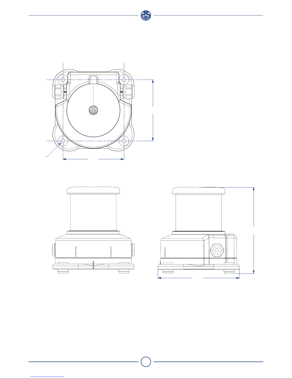
DIMENSIONS
All dimensions in mm.
120
120
Ø8,5
160
169
7Version 3.1 May 2018
Den Haan Rotterdam
AVAILABLE MODELS
Sector lights Min. Visibility Colour Nom. Power Art. Code
Starboard 2 NM Green 4,2 W 60.01.00.00
Port 2 NM Red 4,3 W 60.02.00.00
Masthead 5 NM White 11,7 W 60.03.00.00
Stern 2 NM White 4,1 W 60.04.00.00
Stern red (Suez) 2 NM Red 4,3 W 60.04.07.00
Towing 2 NM Yellow 4,3 W 60.04.09.00
Convoy light 1 NM Blue 4,1 W 60.04.10.00
All-round lights Min. Visibility Colour Nom. Power Art. Code
White 2 NM White 4,1 W 60.06.00.00
Manoeuvring 5 NM White 15,9 W 60.06.10.00
Red 2 NM Red 4,3 W 60.07.00.00
Red & White 2 NM Red/White 4,3 / 5,7 W 60.07.06.00
Red & Green 2 NM Red/Green 4,3 / 5,9 W 60.07.08.00
Green 2 NM Green 4,2 W 60.08.00.00
Yellow1) 2 NM Yellow 4,3 W 60.09.00.00
Blue 1 NM Blue 4,1 W 60.10.00.00
Screened lights2) Min. Visibility Colour Nom. Power Art. Code
White 180° 2 NM White 4,1 W 60.06.01.80
Red 180° 2 NM Red 4,3 W 60.07.01.80
Green 180° 2 NM Green 4,2 W 60.08.01.80
1. Yellow signal light to be used in conjunction with sound signal and only applicable for vessels navigating
the European Inland Waterways
2. - Screened navigation lights should NOT be considered as an official sectored navigation light, but as
two navigation lights with horizontal sectors that combined form a single all round light of 360°
- The interpretation of screened navigation lights are stipulated in IMO MSC.1/Circ.1260

8Version 3.1 May 2018
Den Haan Rotterdam
EXPLODED VIEW
Item Part Material
1 Cover Seawater resistant aluminium,
hard anodized black
2 Gasket Ø91x4mm EPDM - shore 30
3 Screen Seawater resistant aluminium,
hard anodized black
4 Glass Tube Borosilicate glass
5 Heatsink Seawater resistant aluminium
6 LED PCB MC-PCB, aluminium 1.55 mm
7 Cable gland M20x15 Body: Polyamide
Seal: Neoprene
Gasket 28x20x1,5 PTFE
8 Housing Seawater resistant aluminium,
hard anodized black
9 LED driver Potting material: Polyurethane
10 Base plate gasket EPDM - shore 30
11 Base plate Seawater resistant aluminium,
hard anodized black
12 Insulation sleeve Ø8,5 Delrin - black
13 Membrane Vent Body: Silicone rubber
Membrane: ePTFE
14 Plug M20x1,5 Polyamide
Gasket 28x20x1,5 PTFE
1
2
8
14
3
4
56
2
79
10
11
13
12
REPAIR KIT
Gasket Ø91x4 (2x)LED-Driver LED MC-PCB
Item Navigation light Description Number
A Starboard Maintenance kit for: green 60.99.00.30
All-round green
B Port light Maintenance kit for: red 60.99.00.31
Stern Red
All-round red
C Masthead Maintenance kit for: white 5NM 60.99.00.32
D Stern Maintenance kit for: white 2NM 60.99.00.33
All-round white
E Towing light Maintenance kit for: yellow 60.99.00.34
All-round yellow
F All-round blue Maintenance kit for: Blue 1NM 60.99.00.35
G Manoeuvring light Maintenance kit for: Manoeuvring 60.99.00.36
H All-round Red & White Maintenance kit for: Red & white 60.99.00.37
I All-round Red & Green Maintenance kit for: Red & Green 60.99.00.38
Base plate gasket
9Version 3.1 May 2018
Den Haan Rotterdam
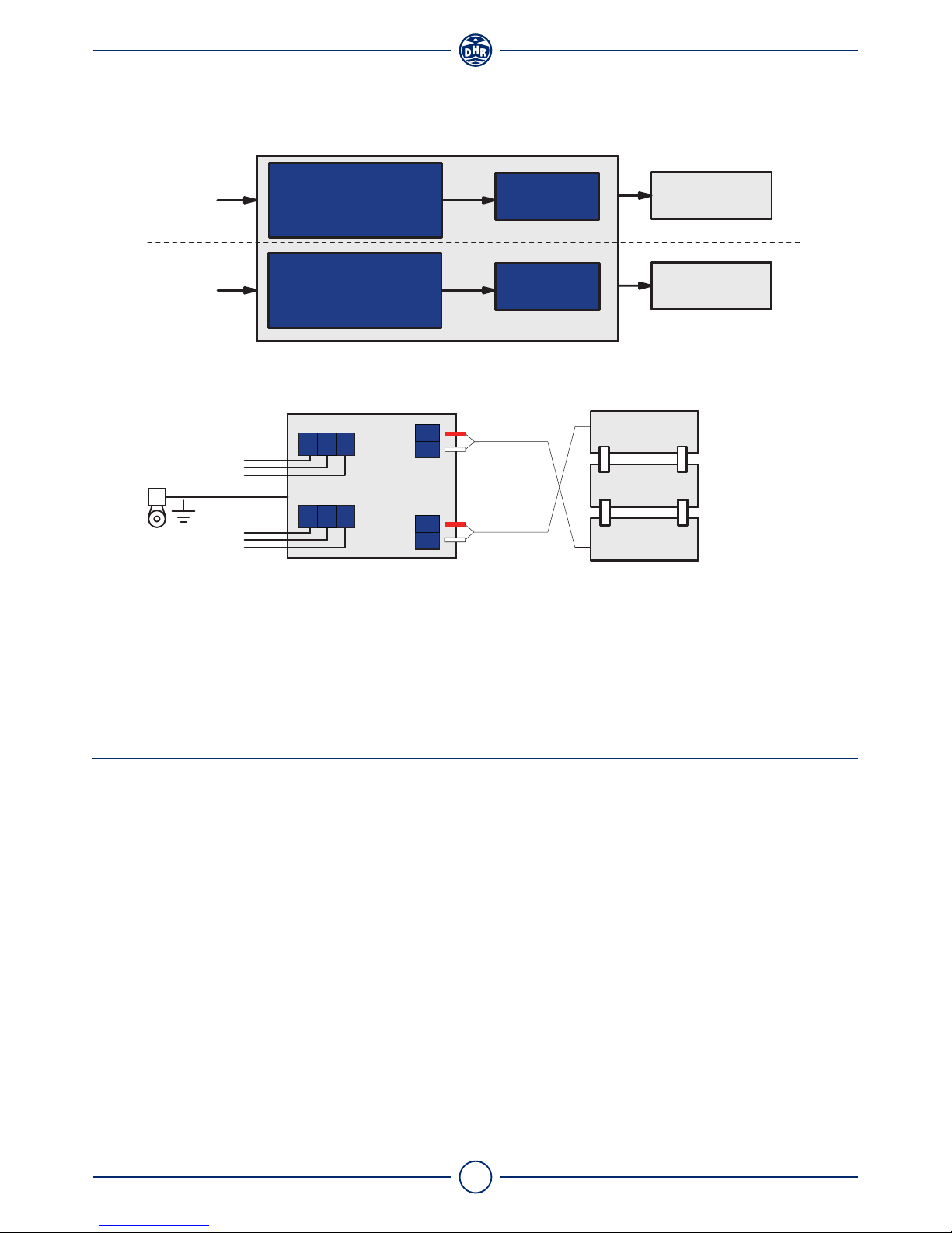
ELECTRICAL SPECIFICATION
Grounding (PE) is not required, but gives better ESD/EMI protection
Navigation light Power Nominal Typical Typical Error Inrush
supply voltage wattage* current* current current
Starboard 350 mA 4,2 W 174 mA
Port 500 mA 4,3 W 179 mA
Masthead 700 mA 11,7 W 489 mA
Stern 350 mA 4,1 W 169 mA
Stern red (Suez light) 500 mA 4,3 W 179 mA
Towing 500 mA 4,3 W 179 mA
Convoy light 350 mA 24 VDC 4,1 W 169 mA >40 mA <10 mA 20 A
All-round white 350 mA 4,1 W 169 mA
All-round green 350 mA 4,2 W 174 mA
All-round red 500 mA 4,3 W 179 mA
All-round red/White 500 mA 4,3/5,7W 179/235 mA
All-round red/Green 500 mA 4,3/5,9W 179/244 mA
All-round yellow 500 mA 4,3 W 179 mA
All-round blue 350 mA 4,1 W 169 mA
* Depends on temperature and LED production series
Power main
24VDC 3-5 LEDS
Output
LED DRIVER
LED driver LED PCB
Power spare
24VDC 3-5 LEDS
Output
LED DRIVER
Galvanic separation
(MAIN)
(SPARE)
PE
1
2
Spare 24VDC
Main 24VDC
1+
2 -
PE - +
1
2
1+
2 -
PE - +
Red cable ferrule
White cable ferrule
Red cable ferrule
White cable ferrule
Minimum
operating
current
10 Version 3.1 May 2018
Den Haan Rotterdam
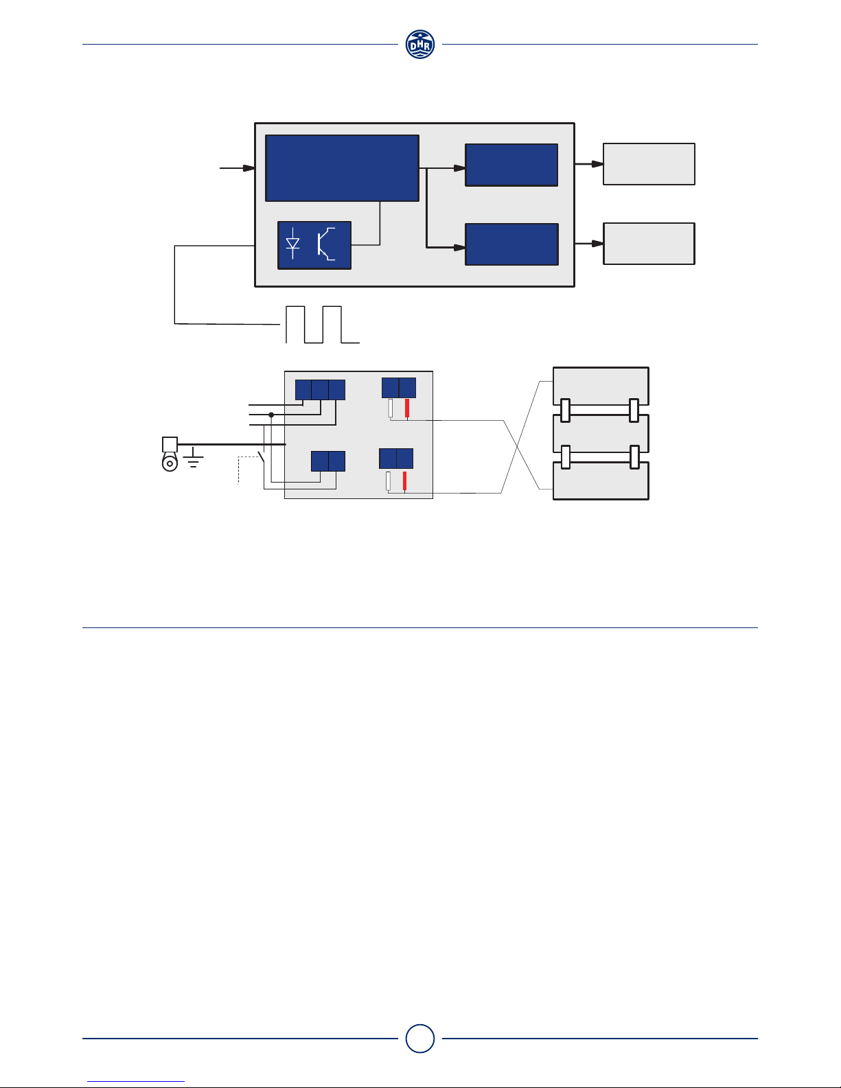
ELECTRICAL SPEC. MANOEUVRING LIGHT
Grounding (PE) is not required, but gives better ESD/EMI protection
Navigation light Power Nominal Typical Typical Error Inrush
supply voltage wattage* current* current current
Manoeuvring 700 mA 24 VDC 15,9 W 662 mA >40 mA <10 mA 40 A
* Depends on temperature and LED production series
Minimum
operating
current
LIFETIME CONTROL
Measurements of the navigation light and specifications retrieved from the OEM, show a conformity with the
minimum requirements of COLREG 72 at an operational lifetime of 50000 hrs. To guarantee a proper use of
the LED navigation lights, we as a manufacturer advise the following:
• Use the navigation light in combination with a DHR-specified control system, which monitors the status
and operational life time of each individual navigation light
• Each navigation light needs to undergo a quality check at least every 5 years of use to verify it still meets
the requirements of COLREG 72
Power 24VDC 3 LEDS
Output
LED DRIVER
LED driver LED PCB
3 LEDS
Output
PE - +
PE - +
Control
Signal
PE
+24VDC
OVDC
Control signal 24VDC
- +
- +
11 Version 3.1 May 2018
Den Haan Rotterdam
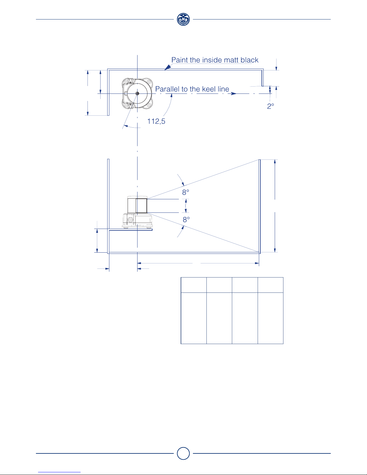
POSITIONING LIGHTS
Disclaimer:
• The minimum luminous intensity requirements in the forward direction are only guaranteed if the
sidelights are mounted in accordance with this drawing and table.
• This is an illustration to indicate the dimensions of the inboard screens, relative to the keel line of the
vessel. By no means may this image be used to determine the position of the sidelights on the vessel.
For positioning the lights at the vessel always check for compliance with COLREG 72 or local rules.
220
110
K
L
J
110
H
200
216
245
273
301
330
98
96
92
89
86
82
345
400
500
600
700
800
0
8
22
36
50
64
H
LKJ
[mm]
12 Version 3.1 May 2018
Den Haan Rotterdam
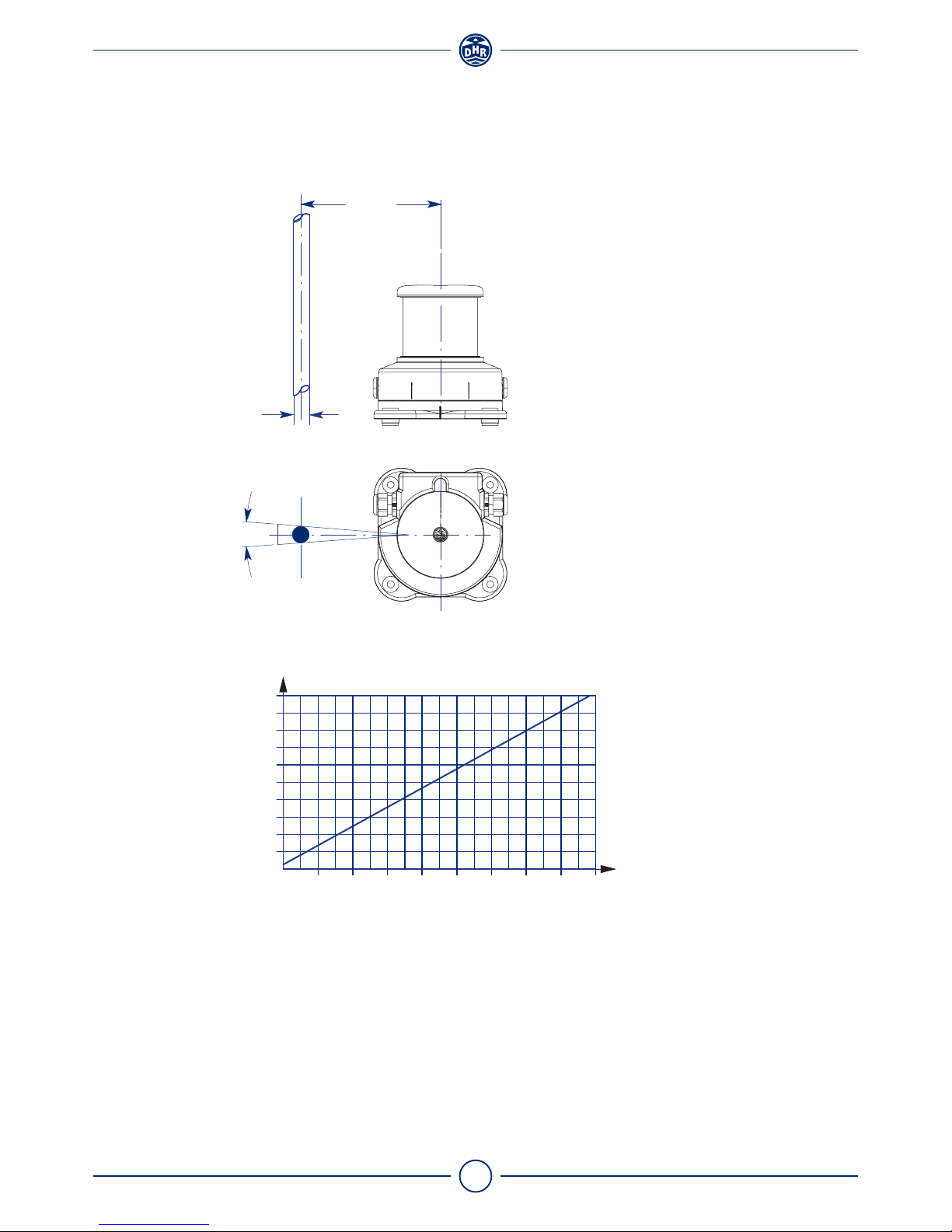
POSITIONING ALL-ROUND LIGHT
Disclaimer:
This is an illustration to indicate the position of the all-round light so not to be obscured by mast, topmasts
or structures within the angular sector of more than 6 degrees. By no means may this image be used to
determine the position of the all-round lights on the vessel. For positioning the lights on the vessel always
check for compliance with COLREG 72 or local rules.
D
1000
180
1600
100 S
160
140
120
200
14001200 1800
Diagram for choosing the minimum distance between
obstacle and mounting plate.
S[mm]
D[mm]
6°
13 Version 3.1 May 2018
Den Haan Rotterdam
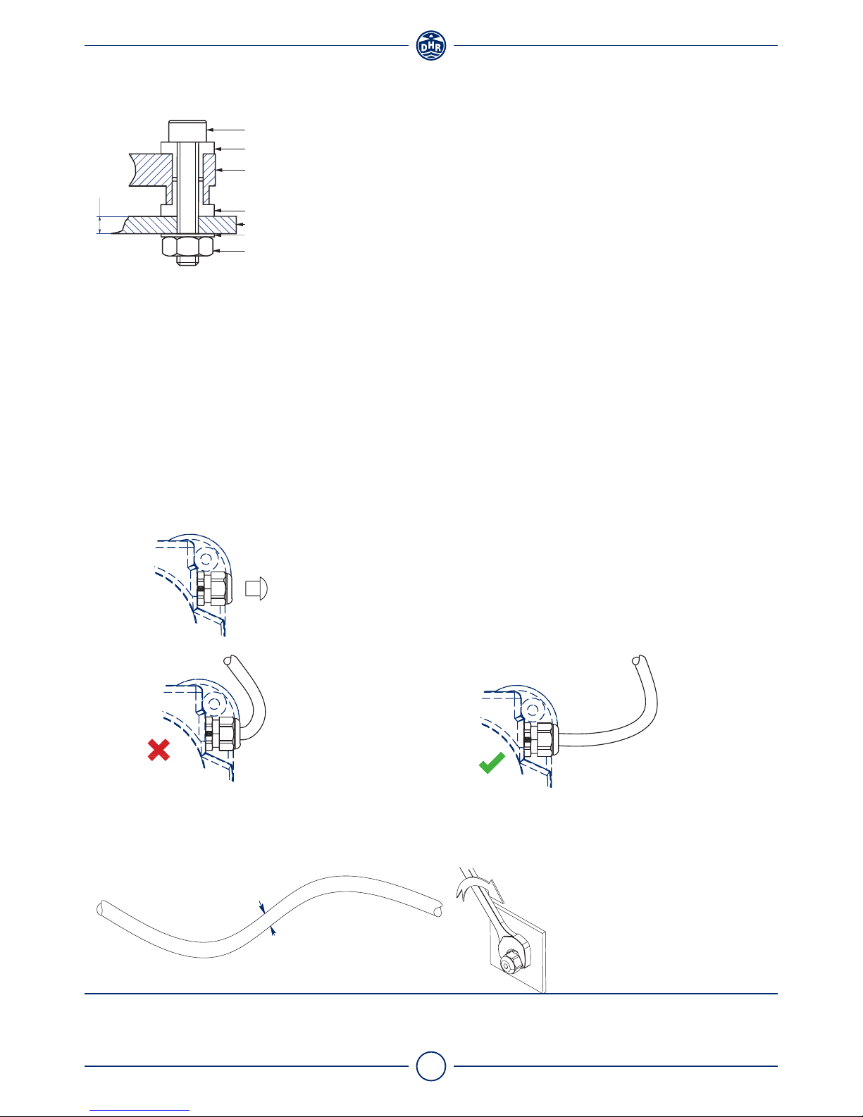
MOUNTING INSTRUCTIONS
Mounting plate
The mounting plate for navigation lights should be at least 3 mm thick and should not exceed a parallelism
of // 00,5.
Fasteners
• The permissible torque should be 6 Nm
• Use only A4-grade stainless steel
Caution!
Even though the housing is made of corrosion resistant materials, galvanic corrosion may still occur.
To prevent galvanic corrosion use the insulation sleeves to isolate the aluminium housing from other
metal parts.
Cable glands
Important
Do not paint or use any other chemical for the lanterns, clean only with fresh water.
Bolt M8 x (35 + M)
Insulation sleeve
Lantern base
Insulation sleeve
Washer M8
Mounting plate Min. 3 mm
Nut M8
M
All dimensions in mm
ØD
Preferred cable diameter D is 6 - 9 mm
Cable too tight!
This gives unwanted stress at the sealing of the
cable gland and water ingress will occur.
Include cable slack at the entering
point of the cable gland
Replacing cable gland
• Use gasket between housing
and cable gland
• Tighten firmly (6Nm) with
wrench
Remove the plug before placing the cable.
If no cable is connected leave the plug in place!

14 Version 3.1 May 2018
Den Haan Rotterdam
Wiring recommendations
EU:
• Neoprene cable H07 RN3x1.5
• Cable diameter 6 - 9 mm
USA:
• Type SJ or equivalent and comply with UL 62 and IEEE 45- 83
• Wire gauge16 AWG
• No. of conductors 3
• Cable diameter 6 - 9 mm

15 Version 3.1 May 2018
Den Haan Rotterdam

S
I
N
C
E
1
9
2
2
ADVANCED MARITIME
SIGNALLING SOLUTIONS
Den Haan Rotterdam
Fascinatio Boulevard 1182
2909 VA Capelle a/d IJssel
The Netherlands
T+31 (0) 10 413 07 55
Esales@dhr.nl
www.dhr.nl
Table of contents
Other DHR Lighting Equipment manuals


