Energetiq LDLS EQ-1500 User manual

Model EQ-1500
LDLS™
Laser-Driven Light Source
Operation Manual
Revision 6 March 2013
Part Number DOC-4958

ii
Copyright © 2013 Energetiq Technology Inc. All rights reserved.
Energetiq products are covered by US and foreign patents. All technical information, including
drawings, schematics and specifications contained in this manual are the property of Energetiq
and shall not be reproduced in whole or in part without the written consent of Energetiq. The
content of this manual is subject to change without notice.
Energetiq Technology Inc.
7 Constitution Way, Woburn, MA 01801 USA
Tel. +1 (781) 939-0763
Fax +1 (781) 939-0769
E-mail: [email protected]
http://www.energetiq.com

i
ii
Declaration of Conformity
We, the manufacturers
Energetiq Technology Inc.
7 Constitution Way
Woburn, Massachusetts USA
hereby declare that the product
LDLS™ Laser-Driven Light Source
Model EQ-1500 Extreme High Brightness Broadband Light Source
is in conformity with the requirements of the following standards
EN61010-1 (2001) Safety Requirements for Electrical Equipment for
Measurement, Control and Laboratory Use: Part 1 –
General Requirements
CISPR 11:2003 Industrial, scientific and medical equipment - Radio-
frequency disturbance characteristics - Limits and methods
of measurement
IEC61000-3-2:2006 Harmonic Emissions
IEC61000-3-3:1995 Fluctuations and Flicker
+ A1:2001 + A2:2005
IEC61000-4-2:2001 Electrostatic Discharge Immunity
IEC61000-4-3:2002 Radiated Electromagnetic Field Immunity
IEC61000-4-4:2004 Electrical Fast Transient Burst Immunity
IEC61000-4-5:2001 Surge Immunity
IEC61000-4-6:2003 Radio Frequency Common Mode Immunity
IEC61000-4-8:1994 Power Frequency Magnetic Field Immunity
IEC61000-4-11:2004 Voltage Interrupts
EN61326-1:2006 Electrical equipment for measurement, control and
laboratory use. EMC requirements. General requirements
EN60825-1 (2007) Safety of laser products - Part 1: Equipment classification
and requirements
in accordance with the provisions of
2006/95/EC EU Low Voltage Directive
2004/108/EC EU Electromagnetic Compatability Directive.
Signed,
25 July 2011
Paul Blackborow, CEO Date
at Woburn, Massachusetts USA

i
v

v
TABLE OF CONTENTS
Chapter 1............................................................................................................................................... 1
General Information.................................................................................................................... 1
Safety........................................................................................................................................ 1
Chapter 2............................................................................................................................................... 9
Description .................................................................................................................................... 9
General.................................................................................................................................... 9
Specifications.......................................................................................................................... 9
Identification of Controls .................................................................................................. 11
Controller Unit .................................................................................................................... 11
Lamp House Unit ............................................................................................................... 15
Chapter 3............................................................................................................................................. 19
Installation ................................................................................................................................... 19
Unpacking............................................................................................................................. 19
Facilities Connections......................................................................................................... 19
Installation procedure......................................................................................................... 23
Chapter 4............................................................................................................................................. 27
Operation..................................................................................................................................... 27
Remote Mode ...................................................................................................................... 28
Chapter 5............................................................................................................................................. 31
Maintenance and Troubleshooting ......................................................................................... 31
Fiber Cleaning Process....................................................................................................... 31
Troubleshooting .................................................................................................................. 34

v
i

EQ-1500 Operation Manual Rev 6 1
Chapter 1
GENERAL INFORMATION
Safety
WARNING
CAUTION
The EQ-1500 emits dangerous levels of UV radiation. Even short
exposures to skin or eyes may cause burns. Ensure that only
authorized personnel are in the vicinity of source during operation.
Personnel in vicinity of operating source should wear protective
eyewear, clothing, and gloves. Lighted UV warning lights and signs
posted on doors to lab areas may help prevent accidental exposure.
This unit emits ultraviolet (UV) radiation that is harmful to humans.
Avoid exposure to the direct or reflected output beam. Make certain
that the appropriate output beam shields and optics are in place prior
to energizing the unit. All interlocks must be satisfied prior to
operation; failure to do so may lead to hazardous conditions.
EQ-1500 Operation Manual Rev 6
2
WARNING
General Precautions
The output beam from the EQ-1500 should be blocked when not in use with an electronic
shutter or other appropriate beam blocking device. Due to the absorption of the short
wavelength light and the possibility of ozone production, the beam should always be either
directly coupled to a fiber optic cable, or enclosed in an appropriate beam pipe, tube, or
enclosed space. We suggest purging any beam transport space with dry Nitrogen gas, as this is
also required for safe operation of the EQ-1500.
The source must be purged with dry nitrogen gas via the nitrogen input connector on the lamp
head. The unit must be purged for a minimum of 10 minutes prior to operation in order to
ensure that no ozone is created by residual oxygen inside the unit. It is recommended that any
beam transport be purged for a similar amount of time.
The EQ-1500 controller must be connected to an appropriate closed-loop water chiller
system. The water system must be capable of maintaining 0.5gpm at 22°C with a minimum of
200W cooling capacity
The EQ-1500 source must also be cabled correctly and connected to a socket with a protective
earth ground prior to operation. Failure to do so may result in an electrical shock hazard.
Refer to the Installation section of this manual (Chapter 3) for details of the facilities
connections.
The EQ-1500 utilizes an internal Class 4 IR laser
capable of causing severe injury to eyes or skin. Do
not open or attempt to service this unit. Contact
Energetiq regarding any problems with the unit.

EQ-1500 Operation Manual Rev 6 3
There are no user-serviceable parts inside the EQ-1500. For any problems encountered during
operation, please refer to the Troubleshooting section of this user manual. If there is a
component failure, do not attempt to open the chassis of the EQ-1500.
The EQ-1500 utilizes a quartz lamp containing a high-pressure gas fill. Explosion of the lamp
and possible injury from flying fragments can occur if the lamp is mishandled. Never attempt
to remove or replace the lamp. If there is a failure of the lamp, the unit must be shipped
back to the factory for refurbishment.
Do not open the chassis of either the lamp unit or the power supply unit. Dangerous
invisible infrared laser beams and hazardous voltages exist inside the units. Opening
the chassis both voids the warranty and exposes the user to dangerous radiation and hazardous
voltages.
CAUTION
CAUTION
The EQ-1500 must be operated for its intended use and as
described in this operating manual. Operation in an un-intended
manner may result in dangerous conditions.
Use of controls or adjustments or executing procedures other
than those specified herein may result in hazardous radiation
exposure.
EQ-1500 Operation Manual Rev 6
4
Laser Information
The EQ-1500 uses a patented (U.S. Patent #7,435,982, others pending) laser drive system to
excite a plasma that radiates in the UV as well as the visible bands. Since the lamp unit
contains an embedded laser, the EQ-1500 is defined as a Laser Product. However, the drive
laser does not exit the system.
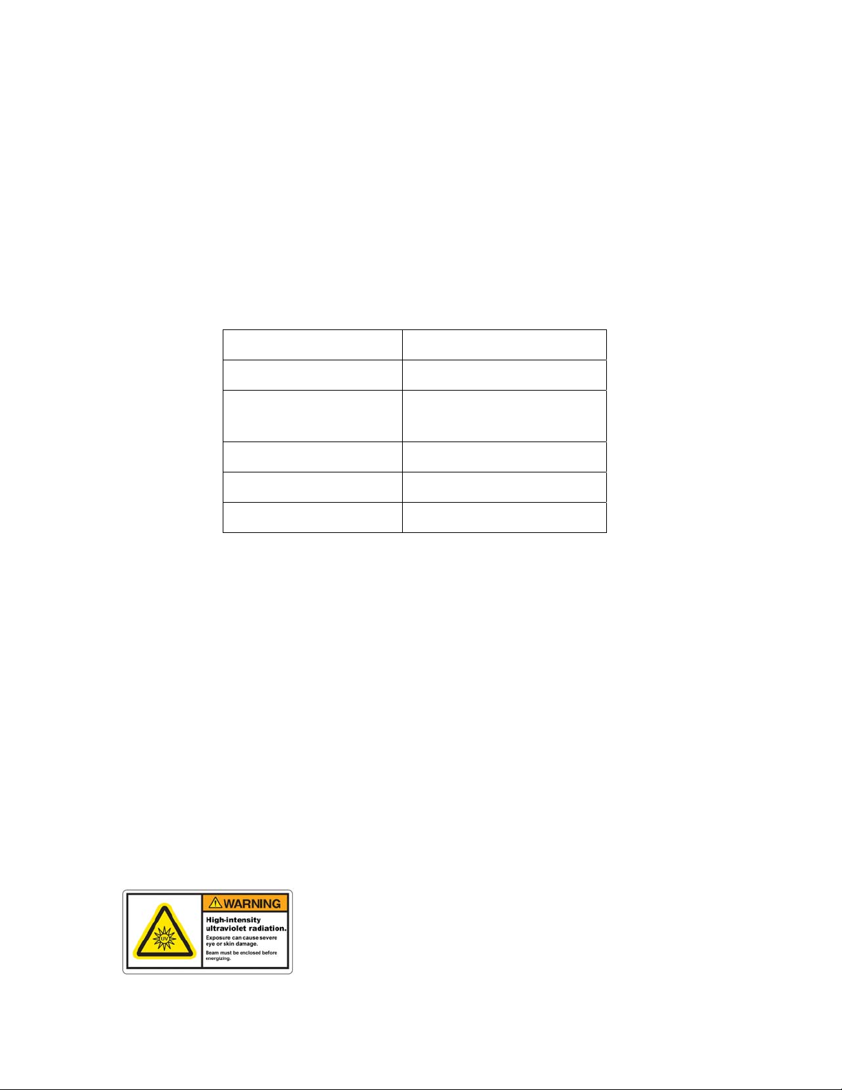
The parameters of the non-accessible internal laser are given below in Table 1.
Wavelength 975 nm
Emission Type CW
Laser Power for classification <40 mW via 7mm measurement
aperture
Beam Diameter ~25 mm at aperture
Divergence >100 mRad
Transverse Beam Mode Highly irregular, diffuse
Table 1: Embedded Laser Parameters
No regular service or maintenance is required. Any service to the system must be performed
only by factory authorized and trained technicians. To avoid eye injury, under no
circumstances should the user open or modify the lamp unit.
The unit must not be operated if the covers are removed or it is defective in any way. Contact
Energetiq if any problems with the equipment are suspected.
Labels and Safety Notification
The following safety labels appear on the product. Figure 1 shows the location of each label
on the EQ-1500 lamp unit.
UV Hazard warning label – indicates hazardous levels of UV
light are present.

EQ-1500 Operation Manual Rev 6 5
Manufacturer’s identification label – gives the manufacturer’s
name and address, and the model, serial number, and date of
manufacture of the equipment.
Explanatory label – states the classification of the laser product.
Class 1 is the lowest hazard level classification.
Certification label – states that the equipment has been tested
and verified to meet the standards indicated.
Interlocked housing label – notifies of a potential hazard when
covers are removed and interlocks failed or defeated.
Protective Ground (Functional Earth) symbol

EQ-1500 Operation Manual Rev 6
6
Figure 1: Safety label locations
Cover Interlocks
The EQ-1500 is equipped with cover interlock switches to prevent operation of the source
without the lamp unit and controller covers in place. Since no user service is permitted, these
switches are intended for the protection of factory service personnel.
External Interlock
An external interlock connector is provided for the customer’s use. Any suitable
normally-open contact can operate the interlock circuit. The unit is shipped with a shorted
connector which may be used to connect to the user’s interlock circuitry. The interlock circuit
must not be grounded.
Interlocked
Housing Label Explanatory
Label
Interlocked
Housing Label
UV Warning
Label Manufacturer’s ID
Label
Certification
Label
Functional
Earth Symbol

EQ-1500 Operation Manual Rev 6 7
The interlock circuit must be connected to enable the operation of the unit. Should the
interlock connection open during operation or standby, the source is immediately disabled, and
all light output from the aperture ceases. The source is then latched off and will not restart
until the interlock is restored and the lamp manually restarted.

EQ-1500 Operation Manual Rev 6
8

EQ-1500 Operation Manual Rev 6 9
Chapter 2
DESCRIPTION
General
The EQ-1500 is a DUV lamp system for a wide variety of applications. The lamp features
high brightness, broad-band light from DUV wavelengths through visible and beyond. The
output is very stable, and has a long lifetime before any service is required. The interface is
quite simple, but robust enough for any lab or industrial environment.
The EQ-1500 system consists of a Controller unit, Lamp House unit, interconnecting
signal/power cable, and interconnecting laser fiber optic cable. Connections to AC power,
cooling water, and purge gas are required for operation.
The Controller unit contains the IR laser, laser power supply, laser cooling, a permanently
attached laser fiber optic cable, and control electronics.
The Lamp House unit contains the lamp, igniter, laser focusing optics, and interlocks.
Specifications
DUV Performance
Typical output spectrum: see Figure 2.
oUpper, Blue line: typical EQ-1500 output
oLower, Red line: typical D2 lamp output

EQ-1500 Operation Manual Rev 6
10
Figure 2: Typical output spectrum
Physical Specifications
System Dimensions (H x W x D), Weight
Lamp House 175 x 142 x 218 mm (6.9 x 5.6 x 8.6 in)
Controller 142 x 254 x 419 mm (5.6 x 10.0 x 16.5 in)
Weight
Lamp House 5 kg (11 lbs)
Controller 6.5 kg (14.3 lbs)
Utility Requirements
Electrical 100–120/200–240 VAC ±10%, 50/60Hz, 300VA max.
Fuse: 250VAC, 8A Fast
Cooling Water 0.03–0.07 MPa (5–10 psi) differential, 1.9–3.8 lpm (0.5–1 gpm),
22°C inlet temperature, controlled within ± 1.0°C
Purge Gas: Dry nitrogen, grade 6 preferred, 0.14 MPa (20 psig), 1 slpm, filtered to
5um
0.001
0.01
0.1
1
10
100
180 280 380 480 580 680 780
Wavelength (nm)
Spectral Radiance (mW/mm^2/nm/sr)

EQ-1500 Operation Manual Rev 6 11
Environmental Requirements
Operating
Temperature: 5–40°C
Relative Humidity: non-condensing, 80% max. for temperatures up to 31°C,
decreasing linearly to 50% max. at 40°C
Altitude: 2000 m (6562 ft) max.
Pollution Degree 2 (normally only non-conductive pollution; occasional,
temporary condensation possible)
Installation Category II
Indoor use only
Transport
Temperature: -5–95°C
Relative Humidity: non-condensing, 95% max.
Identification of Controls
The following sections show the location of controls and other features, and give an overview
of their functions. Refer to the “Installation” section of this manual (Chapter 3) for more
detailed information.
Controller Unit
Figure 3: Controller front panel
Operation
Selector Switch
Status Indicator
LEDs

EQ-1500 Operation Manual Rev 6
12
Operation Selector Switch
Momentary switch used to start or stop UV light output, or to clear a Fault condition.
Status Indicator LEDs
Lamp controller Status
LEDs
LED
Color
Functional Description
Power Green AC power is applied and power switch is on
Controller Interlock OK Green All interlocks in the Lamp Controller are
satisfied
Lamp House Interlock OK Green All interlocks in the Lamp House are
satisfied
External Interlock OK Green External interlock is satisfied
Remote Control Green Remote Control has been activated via
connector J6. Local Control via the front
panel Operation Selector Switch is disabled.
Laser On Green Laser current is on (Lamp on command has
been asserted)
Lamp On Green Plasma has ignited and is operating
Lamp House Overtemp Red Bulb housing temperature has exceeded 90C
(cooling failure)
Lamp Controller Overtemp Red Safety interlock for cold plate temperature
has exceeded 70C (cooling failure)
Laser Overtemp Red Unit has shut off due because laser
temperature has exceeded 40 degC. Cooling
water flow or temperature for Lamp
Controller is insufficient.
Excess Laser Current Red Laser current has exceeded 9A (does not
stop operation)
Laser Fault Red Indicates that the laser has been disabled
due to a fault. The Controller has requested
laser power, but an IR sensor in Lamp
House did not detect laser power.
Prior to Ignition:
1. The unit has shut down due to a
separate interlock fault
2. The plasma has failed to ignite.
3. A failure has occurred in the laser
fiber.
After Ignition:
1. A failure has occurred in the laser
fiber or laser delivery optics.
Table 2: Front Panel LED functions
EQ-1500 Operation Manual Rev 6 13
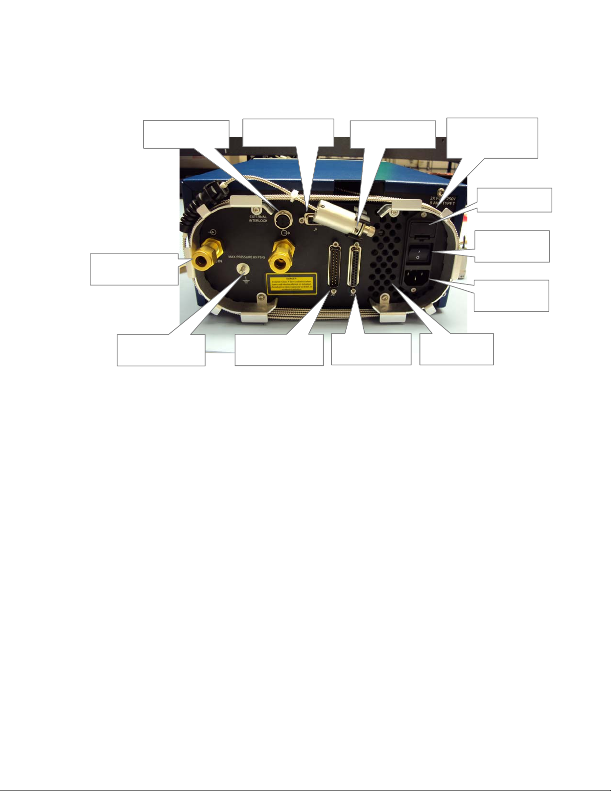
Figure 4: Controller rear panel
Interlock Connector
Connection point for a user-supplied external interlock contact. Contact must be closed or
connector jumpered to enable operation. We recommend that any door or enclosure switches
in the user’s system be wired in series with this interlock connection.
Laser Connection to Lamp House
Connects to the Lamp House to supply laser energy to the lamp via the fiber cable.
J4 Remote Sensor Connector
Connection point for a user-supplied photosensor, when using remote control/remote sensing
mode.
Interlock
Connector
J5 Lamp House
Connector
Power Entry
Connector
Power On/Off
Switch
Fuse Drawer
Cooling Fan
Exhaust
J6 Remote
Control Connector
J4 Remote Sensor
Connecto
r
Armored Laser
Fiber (coiled for
storage)
Cooling Water
Connections
Functional Earth
Terminal
Laser Connection
to Lam
p
House

EQ-1500 Operation Manual Rev 6
14
Armored Laser Fiber
Transmits laser energy from the Controller to the Lamp House. Handle the fiber gently and
avoid creating sharp bends or kinks in the cable. Minimum bend radius for the cable is 30 mm
(1.2 in). See instructions in Chapter 3 under “Installation Procedure” for details on inspecting,
cleaning and installing the fiber.
Fuse Drawer
Two AC line fuses are installed in this fuse holder. The fuse type is 250V, 8A, Fast, 5 x 20mm
Power On/Off Switch
This switch is used as a main AC power switch. It can also be used as an emergency off
switch.
Power Entry Connector
The power input connection to the EQ-1500 is made via a standard IEC 3-pin power entry
module. A power cable is included with the system, but any standard cable can be used.
Cooling Fan Exhaust
The internal laser power supply is air cooled. To avoid overheating, do not obstruct this fan
exhaust.
J5 Lamp House Connector
Provides power and control signals to the Lamp House. No connector or cable may be used
with the EQ-1500 other than the one supplied.
J6 Remote Control Connector
Provides access to control and status signals when operating the EQ-1500 in remote control
mode.
Cooling water connections
Standard Swagelok® connectors for cooling water supply and return, providing cooling for the
internal diode laser.
Table of contents
Other Energetiq Lighting Equipment manuals


Popular Lighting Equipment manuals by other brands


ALPHA LITE
ALPHA LITE DS-PAD User manual book

ML Accessories
ML Accessories NH023AW Installation & maintenance manual

Cooper
Cooper Metalux CGTS NUV instructions

Heitronic
Heitronic 39689 installation instructions

Linergy
Linergy PRODIGY PR08F10EBR Installation and use instructions

superbrightleds
superbrightleds XSCS-RW user manual