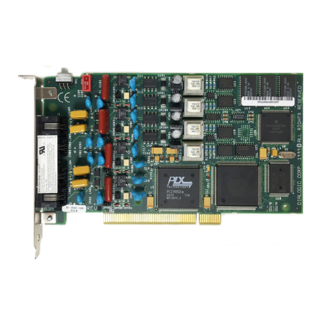
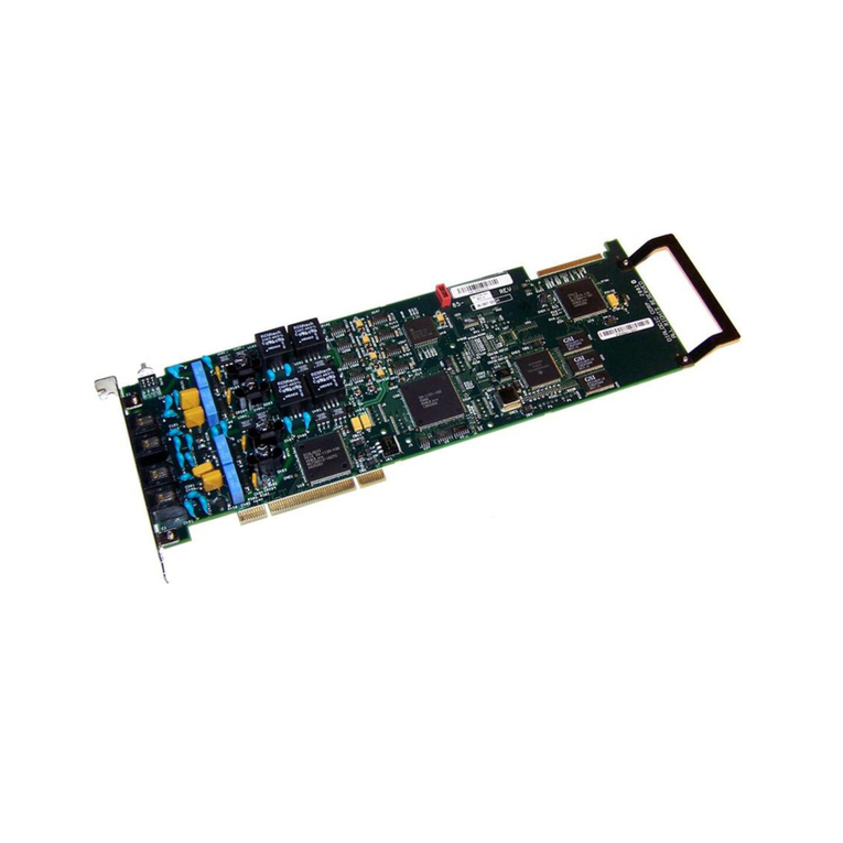
Dialogic D/41EPCI User manual

OneBox and Ericsson are registered trademarks of Ericsson Enterprise AB. Dialogic is a registered trademark, and D/41EPCI, D/120JCT-LS, D/240PCI-T1,
D/41D, D/160SC-LS, D/240SC-T1, and D/4PCI are trademarks of Dialogic Corporation, an Intel Company. Brooktrout is a trademark of Brooktrout Technology, a
Brooktrout Company.
All other products, brand names, or companies mentioned in this document may be trademarks or registered trademarks of their respective companies.
R3B Copyright ãEricsson Enterprise AB 2000–2001
All rights reserved.
Dialogic PCI Linecard Installation and Replacement
Inside this Document:
Before You Begin...........................................................................................................................................2
Technical Specifications of Dialogic PCI Linecards.......................................................................................3
Preparing Dialogic PCI Linecards for Installation ..........................................................................................6
Installing Dialogic PCI Linecards in the Platform .........................................................................................11
Cabling Dialogic Linecards to the Telephone System .................................................................................14
Installing Dialogic System Software.............................................................................................................22
Configuring Dialogic PCI Linecards in Dialogic Configuration Manager......................................................30
Adding a Linecard to the Configured Devices List.......................................................................................38
Configuring Lines in OneBox Configuration ................................................................................................40
Setting the Signaling Protocol Used by D/240PCI-T1 Linecards................................................................41
Testing and Troubleshooting T-1 Equipment ..............................................................................................45
This document explains how to install or replace one or more Dialogic®D/41EPCI™,
D/120JCT-LS™, or D/240PCI-T1™linecards in a OneBox®platform. It also explains how to
install Dialogic System Software versions 2, 3.3, and SR5.01. The information in this document
pertains to platforms running version 1.1 or later of OneBox.
We recommend that you read this entire document before disassembling the hardware.
IMPORTANT
Hardware conflicts and configuration issues can occur between hardware devices installed in a computer
platform. Because Ericsson sells Dialogic PCI linecards as a kit for installation in computer platforms that
we have not tested, we cannot guarantee the compatibility of these cards in your computer platform.
Ericsson will offer troubleshooting advice and assistance to the best of its knowledge and ability. However,
you are ultimately responsible for resolving all hardware conflicts and configuration issues.
Dialogic PCI linecards cannot be used in a computer platform that also contains Dialogic ISA linecards
(includes D/41D, D/41ESC, and D/160SC-LS). If ISA linecards are currently installed in the platform, they must
be removed prior to installing the PCI linecards. Dialogic PCI linecards can be used in conjunction with all
Brooktrout™fax cards.
This document does not discuss how to install or configure the Dialogic D/4PCI linecard. Although we sell
this card for use in telephony server platforms, it lacks the telephony bus connections to be fully compatible
with the other linecards that we support. For information on installing and configuring D/4PCI linecards,
please see the spare parts document Dialogic D/4PCI Linecard Installation and Replacement.
Dialogic PCI Linecard Installation and Replacement
R3B ãAug 2001 Ericsson Enterprise AB
2
Before You Begin
Review this section before performing any of the procedures in this document. This
section provides important information about electrostatic discharge and the tools and
equipment required to complete the installation.
Electrostatic Discharge (ESD) Warning
Computer components are extremely sensitive to electro-static discharge (ESD). You
must wear an anti-static wrist strap and install the linecard at an ESD-safe workstation.
Do not open the static-protective bag until necessary. Before removing the linecard from
the static-protective bag, touch the bag to a grounded, unpainted metal surface for at least
two seconds (this drains the static electricity from the bag and from your body). Turn off
and unplug your computer before removing the case.
Gathering Tools and Equipment
Before you begin disassembling the OneBox platform, verify that you have the following
required tools and equipment:
• OneBox Telephony Server program CD-ROM
• Dialogic System Software program SR5.01 CD-ROM (if applicable)
• One or more Dialogic PCI linecards (D/41EPCI, D/120JCT-LS, or D/240PCI-T1)
• CTbus cable to connect multiple PCI cards
• New feature key diskette (if the total number of ports available after the addition of
new linecards exceeds the number of ports for which you are currently licensed)
• #2 Phillips screwdriver
• Linecord adapters, if necessary
• If you are installing a D/240PCI-T1 linecard, the following additional hardware:
− Channel Service Unit (CSU), may be integrated into the telephone system (switch)
− T-1 line–to–CSU cable
− CSU–to–D/240PCI-T1 cable
Refer to the “Cabling Dialogic D/240PCI-T1 Linecards to the Telephone System” section
for additional information.

Dialogic PCI Linecard Installation and Replacement
R3B ãAug 2001 Ericsson Enterprise AB 3
Technical Specifications of Dialogic PCI Linecards
Tables 1–3 list the technical specifications for the three Dialogic PCI linecards approved
for use with OneBox:
• D/41EPCI 4-port linecard
• D/120JCT-LS 12-port linecard
• D/240PCI-T1 24-channel T-1 card
Figures 1 through 3 show the general layouts of these linecards.
Your local telephone company may require some of these specifications. For example, in
the United States, some telephone companies require an FCC registration number if the
linecard is connected directly to central office (CO) lines. Contact your local telephone
company for its requirements.
Table 1: D/41EPCI technical specifications
Feature Specification
Number of ports 1–4; the OneBox port assignment is determined by the card’s
linecard identification number
Dialing DTMF
FCC registration number EBZUSA-75385-VM-T
Analog network interface On board loop-start interface circuits
Voice coding PCM
Figure 1. Layout of the D/41EPCI linecard
SW1 SW2 CTbus connecto
r
Slot retaine
r
bracket
JP6
JP7

Dialogic PCI Linecard Installation and Replacement
R3B ãAug 2001 Ericsson Enterprise AB
4
Table 2: D/120JCT-LS technical specifications
Feature Specification
Number of ports 1–12; the OneBox port assignment is determined by the card’s
linecard identification number
Dialing DTMF
FCC registration number EBZUSA-34827-KX-N
Analog network interface On board loop-start interface circuits
Voice coding PCM
Figure 2. Layout of the D/120JCT-LS linecard
Slot retainer
bracket
SW1SW100 CTbus connecto
r

Dialogic PCI Linecard Installation and Replacement
R3B ãAug 2001 Ericsson Enterprise AB 5
CTbus connecto
r
JP6
JP7
Slot retaine
r
bracket
SW1 SW2
Table 3: D/240PCI-T1 technical specifications
Feature Specification
Channelization (channel
order)
1–24; the correlation between channelization and OneBox
ports is determined by the card’s linecard identification number
Dialing DTMF
FCC registration number EBZUSA-20078-XD-N
Framing type D4, also known as Superframe (SF)
Digital network interface On board DSX-1 interface
Line coding (receiver) AMI
Line coding (transmitter) AMI
Other equipment
CSU—required
DSU—depends on capabilities of CSU; usually not required
CSU–to–D/240PCI-T1 cable—must have an RJ-48C
connector to connect to the D/240PCI-T1
Ringer equivalence number 0.0A
Supervisory signal
2- or 4-wire E&M—wink-start E&M signaling is the default and
recommended protocol; immediate-start E&M requires manual
configuration
FXS—immediate-start FXS signaling requires manual
configuration
T-1 signaling Robbed bit
T-1 span support Full 24 timeslots (partial and fractional T-1 are not supported)
Timing (synchronization) Loop timing (external clock)
Voice coding PCM
Figure 3. Layout of the D/240PCI-T1

Dialogic PCI Linecard Installation and Replacement
R3B ãAug 2001 Ericsson Enterprise AB
6
Preparing Dialogic PCI Linecards for Installation
Depending on the linecard you are installing, you will need to configure some or all of the
following components of the Dialogic PCI linecard before installing it in the OneBox
platform.
• Assign a linecard identification number based on the ports it will provide.
• Configure the linecard to use an SCbus clock (except on the D/120JCT-LS model).
• In the case of the D/41EPCI and the D/120JCT-LS, configure its default line state.
• If the platform has only PCI expansion slots, remove the slot retainer brackets from
the linecards.
Assigning the Linecard Identification Number
Each Dialogic linecard installed in the OneBox platform must be configured with a
unique linecard identification number (referred to by Dialogic as the Board ID, Board
Locator ID, or Board Locator Technology ID). This number, from 1 through F hex (1–15
decimal), is used by Dialogic System Software to determine which linecard is sending a
signal. If two or more linecards installed in the platform are configured to use the same
linecard identification number, the Dialogic System Software (device driver) will be
unable to locate either linecard. Unique linecard identification numbers must be assigned
in ascending order to each linecard starting at 1.
OneBox assigns line numbers in ascending order based on the linecard identification
number. For example, if you install a D/240PCI-T1 linecard to which you have assigned
linecard ID 1, the 24 channels it provides will be assigned by OneBox the line numbers
1–24. If you then install a D/41EPCI to which you have assigned linecard ID 2, the four
ports it provides will be assigned the line numbers 25–28.
Precedence in Mixed Systems
D/240PCI-T1 linecards must be assigned the lowest linecard identification numbers of
any linecards installed in the platform starting at ID 1. The D/240PCI-T1 will not
function properly if another model of PCI linecard, such as a D/41EPCI, is assigned a
lower linecard identification number. For example, if you are adding two D/240PCI-T1
linecards in a platform that currently has two D/41EPCI linecards, the D/240PCI-T1
linecards must be assigned ID 1 and ID 2, and the D/41EPCI linecards must be changed
to ID 3 and ID 4.

Dialogic PCI Linecard Installation and Replacement
R3B ãAug 2001 Ericsson Enterprise AB 7
IMPORTANT
Do not configure any Dialogic PCI linecard to linecard identification number 0. We do not support
the automatic linecard identification number assignment scheme for PCI linecards (called
Geographic Sequencing by Dialogic).
To set the linecard identification number:
• Dial the rotary switch to select a unique linecard identification number, as shown in
the example in Figure 4.
For the location of the rotary switch, refer to:
- Figure 1 if you are installing a D/41EPCI (SW1)
- Figure 2 if you are installing a D/120JCT-LS (SW100)
- Figure 3 if you are installing a D/240PCI-TI (SW1)
Figure 4. A rotary switch
set to linecard ID 3
3

Dialogic PCI Linecard Installation and Replacement
R3B ãAug 2001 Ericsson Enterprise AB
8
Configuring the Linecard for SCbus Mode
To function in SCbus mode, the CTbus on the linecard must be configured to use an
SCbus clock. You configure the CTbus with hardware using jumpers or with software by
the Dialogic System Software, depending on the linecard you are installing.
• D/41EPCI and D/240PCI-T1 linecards use hardware to configure the CTbus.
• D/120JCT-LS linecards are configured automtically by the Dialogic System Software.
Skip to “Configuring the Default Line State (Hook Switch State).”
To configure a D/41EPCI or a D/240PCI-T1 for SCbus mode:
• Install jumpers on pins 1–2 of JP6 and JP7 as shown in Figures 5 and 6.
For the location of JP6 and JP7, refer to:
- Figure 1 if you are installing a D/41EPCI
- Figure 3 if you are installing a D/240PCI-T1
Figure 5. Jumper blocks JP6 and JP7
Figure 6. Jumpers in place on pins 1 and 2
JP6 JP7
Pin 1
Pin 2
Pin 3
Pin 2
Pin 3
Pin 1
JP6 JP7
CTbus pin

Dialogic PCI Linecard Installation and Replacement
R3B ãAug 2001 Ericsson Enterprise AB 9
Configuring the Default Line State (Hook Switch State)
D/41EPCI and D/120JCT-LS linecards have a configurable default line state (hook switch
state). This setting determines how the linecards will respond to incoming telephone calls
when the OneBox platform is turned on, but either OneBox or the Dialogic System
Software is not running.
• If the switch is in the OFF position, the default line state is onhook; callers will get a
ring-no-answer (RNA) response.
• If the switch is in the ON position, the default line state is offhook; callers will get a
busy signal.
Note If the computer platform is turned off, callers will get an RNA response.
To set the default line state:
• Set the default line state of the linecard to offhook.
If you are preparing a… Then…
D/41EPCI Flip the SW2 switch position 1 to the ON position.
D/120JCT-LS Flip the SW1 switch position 1 to the ON position.
D/240PCI-T1 No configuration is necessary. The default line state for
these cards is offhook.

Dialogic PCI Linecard Installation and Replacement
R3B ãAug 2001 Ericsson Enterprise AB
10
Removing the Slot Retainer Bracket
Depending on the design of the platform, you may need to remove the slot retainer bracket
from the inside edge of the linecard. Refer to Figure 1, Figure 2, or Figure 3 for the location
of the slot retainer bracket.
To remove the slot retainer bracket:
• Choose one:
If the platform is designed for… Then…
PCI cards only Remove the slot retainer bracket from the
end of the card before installing it.
ISA and PCI cards Leave the slot retainer bracket attached.
The slot retainer bracket allows you to
install the card in a platform that contains
both ISA and PCI slots (where the PCI
slots use the ISA form factor).

Dialogic PCI Linecard Installation and Replacement
R3B ãAug 2001 Ericsson Enterprise AB 11
Installing Dialogic PCI Linecards in the Platform
Since Dialogic PCI linecards are designed for the PCI expansion bus, you must assign the
interrupt request queue (IRQ) numbers and memory addresses used by the cards through
the platform’s BIOS instead of by configuring jumpers or switches. The method you use
to do this varies from one platform (and therefore one BIOS) to another. For example,
one BIOS may allow you to assign IRQ 5 to the PCI expansion slots you intend to use for
the linecard, while another BIOS may assign IRQ 5 to a specific PCI expansion slot
automatically based on the slot’s physical location in the platform. On other platforms,
all IRQs are assigned automatically by the BIOS. Refer to the platform documentation
to determine how to configure the platform to assign IRQs to expansion slots used by
PCI linecards.
If you are required to assign explicit IRQs to the PCI linecards in a platform, all of those
linecards must share IRQ 5. After you have prepared the Dialogic PCI linecards for
installation and have determined how to assign IRQs to the expansion slots they will use,
you can install the linecard in the platform.
IMPORTANT
Dialogic PCI linecards cannot be used in a computer platform that also contains Dialogic ISA
linecards (includes D/41D, D/41ESC, and D/160SC-LS). If ISA linecards are currently installed in the
platform, they must be removed prior to installing the PCI linecards. Dialogic PCI linecards can be
used in conjunction with all Brooktrout fax cards.
To install Dialogic PCI linecards:
1. Verify that the linecard identification number, the CTbus, and the default line state (if
applicable) are configured for each linecard, and that its slot retainer bracket is
removed, if necessary (refer to “Preparing Dialogic PCI Linecards for Installation”
for instructions).
2. If necessary, configure the Dialogic system service to start manually.
If Dialogic System Software is… Then…
Installed on the platform Continue to step 3.
Not installed on the platform Skip to step 7.
3. From the Start menu, point to Programs, point to Dialogic System Software, and
select Dialogic Configuration Manager – DCM.

Dialogic PCI Linecard Installation and Replacement
R3B ãAug 2001 Ericsson Enterprise AB
12
4. From the Service menu, point to Startup Mode, and select Manual.
5. From the File menu, select Exit.
6. Shut down the operating system.
7. Turn off the computer, unplug its power cord, and remove its cover.
8. Select a PCI expansion slot.
If the linecard… Then…
Replaces an existing linecard Remove the existing linecard from the PCI
expansion bus slot and use this expansion slot
for the replacement linecard.
Adds ports to the OneBox platform Select an empty PCI expansion bus slot that
will be assigned IRQ 5 and remove its
retaining screw and cover plate.
9. Insert the linecard into the PCI bus slot. Gently press the linecard down to seat the
edge connector into the slot, applying pressure only to the top edge of the board.
Rocking the card or applying excess pressure may damage the card or the bus
connector.
10. Secure the card with the appropriate retaining screw or a locking clip.
Note If you do not secure the card, you can unseat it from the slot when you attach
the CTbus cable later in the installation process.
Select Manual

Dialogic PCI Linecard Installation and Replacement
R3B ãAug 2001 Ericsson Enterprise AB 13
11. Repeat steps 8–10 for each linecard.
12. If you have more than one PCI card installed, cable the cards together.
IMPORTANT
Do not terminate the board at each end of the CTbus cable. CTbus termination jumpers are
ignored when the cards are used in an SCbus configuration.
a. Plug the first (end) connector on the CTbus cable to the CTbus edge connector on
the top edge of the first PCI card.
The connectors are designed to fit together one way only. If the connector does
not seat fully on the card, turn the cable around and try again. When attached
correctly, the colored stripe on the cable faces the rear bracket. (The stripe must be
adjacent to pin 1 on the card connector.)
b. Plug the last (opposite end) connector on the CTbus cable to the CTbus connector
on the last PCI card installed in the platform.
c. Plug a connector on the CTbus cable to the CTbus connector on each remaining
intermediary PCI card installed in the platform.
d. Tuck any extra connectors or loose ribbon cable down into the computer so that it
does not snag when you replace the platform cover.
13. Replace the cover on the platform and plug in the power cord.
14. Proceed to “Cabling Dialogic Linecards to the Telephone System.”

Dialogic PCI Linecard Installation and Replacement
R3B ãAug 2001 Ericsson Enterprise AB
14
Cabling Dialogic Linecards to the Telephone System
Each of the linecards described in this document uses a different type of linecord to
connect to the telephone system. This section discusses each of these different types of
linecord.
Cabling D/41EPCI Linecards to the Telephone System
With the D/41EPCI linecard(s) installed in the platform, you can now cable the platform
to the telephone system. As described in “Assigning the Linecard Identification Number,”
OneBox assigns port numbers in ascending order based on the linecard identification
number. For example, a D/41EPCI linecard to which you assigned the linecard ID 1 will
be assigned line numbers 1–4; a D/41EPCI linecard to which you assigned the linecard ID
2 will be assigned line numbers 5–8 (as shown in Figure 7). Keep this line number
assignment scheme in mind when connecting each D/41EPCI linecard to the telephone
system.
Figure 7. Line assignment scheme for D/41EPCI linecards
Linecard
ID# 1
Linecard
ID# 2
Line 1 Line 5
Line 2 Line 6
Line 3 Line 7
Line 4 Line 8

Dialogic PCI Linecard Installation and Replacement
R3B ãAug 2001 Ericsson Enterprise AB 15
D/41EPCI linecards use RJ-11 connectors to interface with the telephone system.
Depending on the type of linecord your local public telephone network uses, you may
need linecord adapters to connect the computer platform. For example, we ship each
Dialogic D/41EPCI linecard sold in North America with two RJ-11–to–RJ-14 linecord
adapters (shown in Figure 8). These adapters allow you to connect the RJ-11 single-
channel connectors at the back of the D/41EPCI to a two-channel RJ-14 linecord. If
linecord adapters are required and not included with the linecards, please contact your
technical service representative.
Figure 8. RJ-11–to–RJ-14 linecord adapter
To cable D/41EPCI linecards:
• Plug the linecords (jacks) from the telephone system to the RJ-11 connectors on the
D/41EPCI (refer to the line assignment diagram shown in Figure 7).
–or–
If the linecords from the telephone system do not use RJ-11 connectors, plug the
linecords into the appropriate linecord adapter, then plug the RJ-11 linecord(s) of the
adapter into the RJ-11 connectors on the D/41EPCI.
RJ-14 connecto
r
RJ-11 cable
RJ-11 cable

Dialogic PCI Linecard Installation and Replacement
R3B ãAug 2001 Ericsson Enterprise AB
16
Cabling D/120JCT-LS Linecards to the Telephone System
With the D/120JCT-LS linecard(s) installed in the platform, you can now cable the
platform to the telephone system. As described in “Assigning the Linecard Identification
Number,” OneBox assigns port numbers in ascending order based on the linecard
identification number. For example, a D/120JCT-LS linecard to which you assigned the
linecard ID 1 will be assigned line numbers 1–12; a D/120JCT-LS linecard to which you
assigned the linecard ID 2 will be assigned line numbers 13–24 (as shown in Figure 9).
Keep this line number assignment scheme in mind when connecting each D/120JCT-LS
linecard to the telephone system.
Figure 9. Line assignment scheme for D/120JCT-LS linecards
Linecard ID# 1 Linecard ID# 2
Lines 1 & 2 Lines 13 & 14
Lines 3 & 4 Lines 15 & 16
Lines 5 & 6 Lines 17 & 18
Lines 7 & 8 Lines 19 & 20
Lines 9 & 10 Lines 21 & 22
Lines 11 & 12 Lines 23 & 24

Dialogic PCI Linecard Installation and Replacement
R3B ãAug 2001 Ericsson Enterprise AB 17
There are six modified RJ-14 connectors on the rear brackets of D/120JCT-LS linecards.
Figure 10 shows how the pins in these modified connectors are arranged.
Figure 10. Pinouts for the RJ-14 connectors
Note Pins 1 and 6 are not used and should not be connected to the telephone system.
The connectors on the rear brackets of the D/120JCT-LS cards accept linecords
equipped with standard two-line RJ-14 connectors.
Depending on the type of linecord your local public telephone network uses, you may
need linecord adapters to connect the computer platform to the telephone system (switch).
If linecord adapters are required and not included with the linecards, please contact your
technical service representative.
To cable D/120JCT-LS cards:
• Plug the linecords (jacks) from the telephone system to the RJ-14 connectors on the
D/120JCT-LS (refer to the line assignment diagram shown in Figure 9).
–or–
If the linecords from the telephone system do not use RJ-14 connectors, plug the
linecords into the appropriate linecord adapter, then plug the RJ-14 linecord(s) of the
adapter into the RJ-14 connectors on the D/120JCT-LS.
Pin 6: Earth Recall 2 (not used in USA)
Pin 5: Ring 2
Pin 4: Tip 1
Pin 3: Ring 1
Pin 2: Tip 2
Pin 1: Earth Recall 1 (not used in USA)
6
5
4
3
2
1

Dialogic PCI Linecard Installation and Replacement
R3B ãAug 2001 Ericsson Enterprise AB
18
Cabling D/240PCI-T1 Linecards to the Telephone System
With the D/240PCI-T1 linecard(s) installed in the platform, you can now cable the
platform to the telephone system. As described in “Assigning the Linecard Identification
Number,” OneBox assigns line numbers in ascending order based on the linecard
identification number. For example, a D/240PCI-T1 linecard to which you assigned
linecard ID 1 will be assigned line numbers 1–24; a D/240PCI-T1 linecard to which you
assigned linecard ID 2 will be assigned line numbers 25–48 (as shown in Figure 11).
Keep this line number assignment scheme in mind when connecting each D/240PCI –T1
linecard to the telephone system.
Figure 11. Line assignment scheme for D/240PCI-T1 linecards
This section describes the basic equipment for implementing T-1 and how to connect this
equipment to a D/240PCI-T1 linecard. The equipment needed for a T-1 installation is
shown in Figure 12 and explained in the following paragraphs.
Figure 12. Basic T-1 equipment requirements
Linecard
ID #1
Linecard
ID #2
Lines
1–24
Lines
25–48
Network Customer Premise
T-1 line
CSU
(may
include
DSU)
D/240PCI-T1
DSX-1 Interface
Demarc

Dialogic PCI Linecard Installation and Replacement
R3B ãAug 2001 Ericsson Enterprise AB 19
Channel Service Unit
The Channel Service Unit (CSU) is usually the first piece of equipment on the customer
premises that connects to the T-1 line. A CSU is required any time metallic T-1 services
are ordered from a local exchange (all the Regional Bell Operating Companies) or
interexchange carrier (including long-distance carriers like MCI, Sprint, and AT&T).
Metallic T-1 uses wire to carry the signal instead of optical fiber or microwave radio. The
CSU connects a DS-1–level line to DSX-1–compatible customer equipment. The CSU
may be a standalone unit or it may be integrated into a PBX.
The CSU provides functions that are critical to the network. It provides loopback
capabilities for running diagnostic tests to locate where problems are occurring on the T-1
chain. Some CSUs have dial-in capability for performing remote diagnostics.
The CSU is the last point where the signal is regenerated as it leaves the network. It also
provides line equalization, provides voltage protection for telephone company and
customer premise equipment, monitors the T-1 line for violations, and generates “keep
alive” signals and error condition messages. (A “keep alive” signal is a bit stream of all
“ones” used to power repeaters in the circuit when there is no activity on the line.)
The CSU that you connect to the D/240PCI-T1 must support Superframe (D4) format.
Digital Service Unit
A Digital Service Unit (DSU) may be installed at some sites. The DSU traditionally
serves to encode user data from unipolar to bipolar format, frame user data, and interpret
some incoming bipolar patterns as network commands. The D/240PCI-T1 performs most
DSU functions. However, it cannot interpret some bipolar violations from the network as
commands to go into (or out of) loopback modes. Therefore, a DSU should be removed
from most sites when using a D/240PCI-T1. Further, DSU functions are generally
integrated into current CSUs.
D/240PCI-T1 Connection to Other Equipment
The D/240PCI-T1 can connect to certain other equipment without the need for an
additional CSU. For example, the D/240PCI-T1 can connect to a T-1 interface on a 4ESS
(Electronic Switching System) or 5ESS telephone system without a CSU, provided that
the connecting cable to these devices is not over 655 feet (approximately 200 meters) in
length. Confirm these specifications with your carrier.

Dialogic PCI Linecard Installation and Replacement
R3B ãAug 2001 Ericsson Enterprise AB
20
Many PBXs have built-in CSUs or CSU-like functions. The D/240PCI-T1 can connect
directly to these devices provided that the PBX has a DSX-1 interface (the D/240PCI-T1
will not respond to loopback commands when connected this way). See your switch or
PBX documentation to confirm that your equipment has the necessary features.
Although the D/240PCI-T1 and some PBXs have built-in CSU functions, some carriers
require a CSU to be present so that they can perform diagnostics on the T-1 line. Always
consult with your carrier for its requirements.
T-1 Line–to–CSU Cable
T-1 connectors vary from carrier to carrier, but the cable provided by the T-1 carrier
usually consists of two pairs of individually shielded twisted 22-gauge wires (one
transmit pair and one receive pair) terminated in either a DB-15 or modular RJ-48C plug.
When you order service, make sure that the type of plug the carrier provides is compatible
with the type of plug your CSU accepts. Older CSUs may require that you connect the
wires directly to a terminal strip or similar arrangement. Refer to your CSU
documentation for more information.
Wet or Dry T-1
T-1 lines that carry a voltage to power regenerative repeaters are called wet T-1. This
voltage traditionally has also been used to power the CSU at a site. Since 1987, the
Federal Communications Commission no longer requires the carrier to provide line
power, and the trend has been to discontinue its use. T-1 lines without power are called
dry T-1. If your carrier provides dry T-1, then your CSU must have an AC power source.
Check with your carrier to see what kind of line they supply so that you can obtain an
appropriate CSU. Many of the latest CSUs can handle either kind of line.
CSU–to–D/240PCI-T1 Adapter Cable
The D/240PCI-T1 has an RJ-48C connector on the rear bracket. To connect this linecard
to the CSU you can purchase a CSU-to-equipment adapter cable or build one yourself.
The recommended material for the cable is shielded twisted-pair (ABAM 600 or
equivalent) in which each of the two pairs is shielded and the two pairs share a common
shield. This type of shielding helps to avoid crosstalk problems on the line.
Choose an appropriate cable length for your installation. Eighty-five feet (approximately
26 meters) is the maximum recommended cable length between the CSU and the
D/240PCI-T1 for standard T-1 signals (6 volts peak to peak). In general, you should keep
the cable length as short as possible. Refer to your CSU documentation for guidelines
concerning cable lengths greater than 85 feet (26 meters).
This manual suits for next models
2
Table of contents
Other Dialogic PCI Card manuals

Dialogic
Dialogic D/4PCI Use and care manual

Dialogic
Dialogic D/41JCT-LS Use and care manual

Dialogic
Dialogic D/4PCI Use and care manual

Dialogic
Dialogic Brooktrout TR1034 BRI User manual

Dialogic
Dialogic Brooktrout TR1034 BRI User manual

Dialogic
Dialogic D/41ESC Use and care manual

Dialogic
Dialogic Brooktrout TR1034 User manual

Dialogic
Dialogic Brooktrout TR1034 Instruction Manual

Dialogic
Dialogic Brooktrout TruFax User manual

Dialogic
Dialogic DM/V1200A-4E1-PCI Instructions for use