Diamond Systems JASPER User manual

JASPER
COM Express Type 6 Carrier Board and SBC
User Manual
Revision No
Release Date
Comments
1.1
02/08/2023
Initial release
1.2
05/03/2023
General text and image updates
© Copyright 2023
Diamond Systems Corp.
www.diamondsystems.com
FOR TECHNICAL SUPPORT
PLEASE CONTACT:
Email: support@diamondsystems.com

Jasper User Manual V1.2 www.diamondsystems.com Page 2
Contents
1Important Safe Handling Information ............................................................................................................ 4
2Introduction...................................................................................................................................................... 6
2.1 Jasper Product Overview ............................................................................................................................. 6
2.2 Baseboard Variants...................................................................................................................................... 8
2.3 Jasper Ordering Guide................................................................................................................................. 8
2.4 Product Photos............................................................................................................................................. 9
3Functional Overview...................................................................................................................................... 11
3.1 COM Express Carrier System.................................................................................................................... 11
3.2 Power Supply Specifications...................................................................................................................... 11
3.3 Ethernet Ports............................................................................................................................................. 11
3.4 PCIe Link Routing....................................................................................................................................... 11
3.5 SATA M.2 Socket ....................................................................................................................................... 11
3.6 USB ............................................................................................................................................................ 12
3.7 Audio........................................................................................................................................................... 12
3.8 LVDS LCD.................................................................................................................................................. 12
3.9 HDMI........................................................................................................................................................... 12
3.10 Serial Ports................................................................................................................................................. 12
3.11 Data Acquisition.......................................................................................................................................... 13
3.12 Backup Battery ........................................................................................................................................... 13
3.13 Trusted Platform Module (TPM)................................................................................................................. 13
3.14 Utility........................................................................................................................................................... 13
3.15 GPIO Header.............................................................................................................................................. 13
3.16 PCIe Minicard Socket................................................................................................................................. 13
3.17 PCIe104 Expansion.................................................................................................................................... 13
3.18 LED Indicators............................................................................................................................................ 14
4Block Diagram................................................................................................................................................ 15
5Mechanical Drawing ...................................................................................................................................... 16
6Connector and Jumper Location ................................................................................................................. 18
6.1 Jumper Selection........................................................................................................................................ 19
7Connector Pinout Specifications................................................................................................................. 22
7.1 Power In (J16) ............................................................................................................................................ 22
7.2 Battery (J18)............................................................................................................................................... 22
7.3 Fan Connector (J31)................................................................................................................................... 22
7.4 Ethernet (J23 & J24)................................................................................................................................... 23
7.5 Audio (J3) ................................................................................................................................................... 23
7.6 USB 2.0 Ports (J25).................................................................................................................................... 23
7.7 USB 3.0 Ports (J14, J20 & J21).................................................................................................................. 24
7.8 LVDS (J4)................................................................................................................................................... 24
7.9 LCD Backlight (J29).................................................................................................................................... 25
7.10 HDMI (J17 & J22)....................................................................................................................................... 25
7.11 VGA (J2)..................................................................................................................................................... 26
7.12 Serial ports (J19 & J26).............................................................................................................................. 26
7.13 M.2 Socket (J15)......................................................................................................................................... 27
7.14 SATA (J9)................................................................................................................................................... 28
7.15 Analog I/O (J16) and Digital I/O (J13) ........................................................................................................ 28
7.16 Utility (J27).................................................................................................................................................. 29
7.17 GPIO Connector (J5).................................................................................................................................. 29
7.18 PCIe Mini Card (J11 & J12)........................................................................................................................ 30
7.19 PCIe104 Connector (J1)............................................................................................................................. 31
Jasper User Manual V1.2 www.diamondsystems.com Page 3
7.20 COM Express type 6 Compact / Basic connector Pinout (J28 & J30) ....................................................... 32
8I/O Connector List.......................................................................................................................................... 37
9Specifications................................................................................................................................................. 38
10 Limited Warranty............................................................................................................................................ 39

Jasper User Manual V1.2 www.diamondsystems.com Page 4
1 IMPORTANT SAFE HANDLING INFORMATION
WARNING!
ESD-Sensitive Electronic Equipment
Observe ESD-safe handling procedures when working with this product.
Always use this product in a properly grounded work area and wear
appropriate ESD-preventive clothing and/or accessories.
Always store this product in ESD-protective packaging when not in use.
Safe Handling Precautions
Diamond Systems boards are designed with complex circuitry and electronic components that are ESD-
sensitive. This increases the likelihood of the boards incurring accidental damage during handling, installation,
and connection to other equipment.
It is highly recommended that the following precautionary measures and best practices be observed in
sequential order:
•Wear an anti-static Wristband/Strap or/and an antistatic Lab Coat or/and Rubber-soled shoes.
•Spread anti-static mats over the table or work surface or/and anti-static mats on the floor.
•Unpack components and remove them from their anti-static bags only when they are ready to be
used.
•Avoid ungrounded surfaces such as plastic, carpets, floors, or tables, in the work area.
•Handle boards by the edges and their metal mounting brackets. Avoid touching components on the
boards and the edge connectors that connect to expansion slots.
The following information describes common causes of failure found on boards and components returned to
Diamond Systems for repair. It is provided as a guideline to avoid accidental damage.
ESD Damage: This type of damage is typically impossible to detect because there is no visual sign of failure
or damage. In this type of damage, the board eventually stops functioning because of some defective
components. Usually, the failure can be identified, and the chip can be replaced.
To prevent ESD damage, always follow proper ESD-prevention practices when handling computer boards.
Damage During Handling or Storage: Physical damage on boards also occur due to mishandling. A common
observation is that of a screwdriver slipping on the board during installation, causing a gouge on the PCB
surface, cutting signal traces or damaging components.
Another common observation is damaged board corners, indicating the board was dropped. This may or may
not cause damage to the circuitry, depending on components located near the edges. Most Diamond System
boards are designed with a minimum 25 mils clearance between the board edge and component pad. The
ground/power planes are located a minimum of 20 mils from the edge to avoid possible shorting from this type
of damage. However, these design rules do not prevent damage in all situations.
Sometimes boards are stored in racks with slots that grip the edge of the board. This is a common practice for
board manufacturers. Though Diamond Systems boards are resilient to damages, the components located
close to the board edges can be damaged or even knocked off the board if the board lies tilted in the rack.
Diamond Systems recommends that all its boards be stored only in individual ESD-safe packaging units. If
multiple boards are stored together, they should be contained in bins with dividers placed between the boards.
Do not pile boards on top of each other or cram too many boards within a small location. This can cause
damage to connector pins or fragile components.

Jasper User Manual V1.2 www.diamondsystems.com Page 5
Bent Connector Pins: This type of problem can be resolved by re-bending the pins to their original shape
using needle-nose pliers.
The most common cause of a bent connector pin is when the board is pulled off a stack by tugging it at angles
from one end of the connector to the other, in an effort to release it off the stack. Tugging the board off the
stack in this manner can bend the pin(s) significantly.
A similar situation can occur when pulling a ribbon cable off a pin header. If the pins are bent too severely,
bending them back can cause them to weaken or break. In this case, the connector must be replaced.
Power Damages: There are various causes of power-specific damages that can occur while handling the
board. Some common causes such as –a metal screwdriver tip slipping, or a screw dropping onto the board
while it is powered-up, causes a short between a power pin and a signal pin on a component.
These faults can cause over-voltage/power supply problems besides other causes described below.
To avoid such damages, assembly operations must be performed when the system is powered off.
Power Supply Wired Backwards: Diamond Systems power supplies and boards are not designed to
withstand a reverse power supply connection. This will destroy almost all ICs connected to the power supply.
In this case, the board will likely be irreparable and must be replaced. A chip destroyed by reverse or excessive
power will often have a visible hole or show some deformation on the surface due to vaporization inside the
package.
Overvoltage on Analog Input: If a voltage applied to an analog input exceeds the power specification of the
board, the input multiplexer and/or parts behind it can be damaged. Most Diamond Systems boards will
withstand an erroneous connection of up to 36V on the analog inputs, even when the board is powered off,
but not on all boards, and not under all conditions.
Overvoltage on Analog Output: If an Analog output is accidentally connected to another output signal or a
power supply voltage, the output can be damaged. On most Diamond boards, a short circuit to ground on an
analog output will deter any damage to the board.
Overvoltage on Digital I/O Line: If a Digital I/O signal is connected to a voltage above the maximum specified
voltage, the digital circuitry can be damaged. The acceptable voltage range, onmost Diamond Systems boards
connected to digital I/O signals is 0-5V, with overvoltage protection up to 5.5V (-0.5 to 5.5V). Overvoltage
beyond this limit can damage the circuitry.
Other considerations are Logic Signals, which are typically generated between 12V to 24V.
If a Digital I/O Line of 12V to 24V is connected to a 5V logic chip, the chip will be damaged, and the damage
could extend to other chips in the circuit.
IMPORTANT! Always check twice before Powering Up!

Jasper User Manual V1.2 www.diamondsystems.com Page 6
2 INTRODUCTION
2.1 Jasper Product Overview
This Product is a COM Express Compact/Basic type 6 carrier board with PCIe104. The carrier is designedto support
a variety of COM Express modules to provide both rapid product line expansion with a variety of processors and
long life by enabling simple replacement of the COM when the designed-in one becomes obsolete.
The COM Express module mounts on the bottom side of the board, and the PCIe104 expansion sockets are on the
top side. The board dimensions are 4.000” x 5.750”, matching the 3.5 inch form factor in size and mounting hole
pattern. The larger size is necessitated due to the incompatibility between the mounting hole patterns of the two
form factors plus the desire to provide increased PCB coastline for I/O connectors.
A thicker PCB (.090” / 2.3mm), latching I/O connectors, and full -40/+85C operating temperature provide increased
ruggedness, enabling the board to work reliably in mobile and harsh environment applications.
A special feature of Jasper is that most I/O connectors are located along the front edge. This makes it possible to
design and build I/O boards that mate directly to Jasper without the use of cables, to reduce size and increase
ruggedness for rugged systems applications.

Jasper User Manual V1.2 www.diamondsystems.com Page 7
Feature Description and Connector Type
Feature
Description
Connector Type
Power
18V-36V wide input or 12V fixed supply
Signal Terminated to 8 Position Vertical
Connector Header (J16)
RTC
3V power input for RTC functionality
Signal Terminated to 2 Position Vertical
Connector Header (J18)
Ethernet
ETH-1 10/100/1000Mbps from COM module
Signal Terminated to 10 Position RA
Connector Header (J23)
ETH-2 10/100/1000Mbps via I210 Ethernet
controller
Signal Terminated to 10 Position RA
Connector Header (J24)
Mass Storage
2 PCIe minicard socket with USB and SATA
Minicard2 supports Nano SIM interface
2 PCIe MiniCard 52 Position (J11 & J12)
1 M.2 2242 / 2280 SATA/x1 PCIe
M.2 Socket (J15)
1 Standard 7pin SATA connector
SATA Connector (J9)
Audio
HDA to Analog Audio converter
Signal Terminated to 10 Position Vertical
Connector Header (J3)
USB
2x USB 2.0
Signal Terminated to 10 Position RA
Connector Header (J25)
3x USB3.0 / USB2.0
Signal Terminated to 10 Position
Connector Header (J20, J21, J14)
Serial Ports
4 ports Software configurable RS-232/422/485
through SP336 transceivers or 2 RS232 only
Signal Terminated to 10 Position RA
Connector Header (J19, J26)
Display
2x HDMI
Signal Terminated to 20 Position
Connector Header (J17, J22)
1x VGA (Based on the COMe module)
Signal Terminated to 10 Position RA
Connector Header (J2)
1x Dual Channel 24-bit LVDS port with 3.3V / 5V
power option
Signal Terminated to 30 Position RA
Connector Header (J4)
LCD Backlight
LCD backlight power and control signals with 5V /
12V power option
Surface Mount 6 Position Connector
Receptacle (J29)
Analog/Digital IO
16 Single ended/ 8 Differential ended Ain
4 Aout
22 Programmable direction digital I/O, 3.3V/5V
logic compatible
Analog Signal Terminated to 30 Position
Vertical Connector Header (J6)
DIO Signal Terminated to 20 Position
Vertical Connector Header (J13)
PCIe104
4 PCIe x1 ports, 1x PCIe x16
Signal Terminated to 156 Position Vertical
Connector Header (J1)
Others
4 GPI, 4 GPO, I2C, Reset Button, Power Button
…………………………………………………
Operating System Support
Windows 10; Ubuntu; Linux
Mechanical, Electrical and Environmental Properties
Form-Factor
4.000” x 5.750”
Cooling Mechanism
Conduction cooling with bottom side heat spreader (target heat spreader height 13mm as per
COM express specification)
Power Input Range
18V-36V wide range input or Fixed 12V +/-10% supply
Operating
Temperature Range
-40°C to +85°C ambient (final system capability depends on the COM installed)

Jasper User Manual V1.2 www.diamondsystems.com Page 8
2.2 Baseboard Variants
Feature
Baseline
JSP-BB01D
Full-Feature
JSP-BB02D
Full Feature w/ DAQ
JSP-BB03A
Gigabit Ethernet
1
2
2
Minicard socket
2
2
2
M.2 socket
1
1
1
SATA connector
1
1
1
HDMI
2
2
2
VGA*
1
1
1
LVDS
1
1
1
USB 3.0
3
3
3
USB 2.0
2
2
2
Serial
2x RS-232
4x RS-232/422/485
(Jumper for protocol
selection)
4x RS-232/422/485
(SW control for
protocol selection)
PCIe104
No
Yes
Yes
Audio
No
1
1
Analog/Digital
IO
No
No
16 SI/8 DE Ain
4 Aout
22 DIO
Others
4 GPI, 4 GPO
I2C
Reset & Power Button
4 GPI, 4 GPO
I2C,1x RS232
Reset & Power Button
4 GPI, 4 GPO
I2C, 1x RS232
Reset & Power Button
2.3 Jasper Ordering Guide
The table below lists the available standard configurations for the carrier board. As the board can work with
multiple COMs, new COMs are tested and added regularly, so check the Diamond website for currently available
SBC processor options. In general when a new COM is added, OS support will also be available for the current
versions of Windows and Ubuntu Linux.
JSP-BB01D
Jasper COM Carrier, low cost model, 18-36VDC In
JSP-BB02D
Jasper COM Carrier, PCIe/104 expansion, Digital I/O, 18-36VDC In
JSP-BB03A
Jasper COM Carrier, PCIe/104 and Data Acquisition, 18-36VDC In
6882210
Mounting Plate for Jasper Carrier (included with the carrier board)

Jasper User Manual V1.2 www.diamondsystems.com Page 11
3 FUNCTIONAL OVERVIEW
The following section provides functional details of the key sub-systems implemented on the baseboard.
3.1 COM Express Carrier System
Jasper supports COM Express Compact (95x95mm) and Basic (95x125mm) Type 6 modules. The availability of
features is dependent on both the COM and the baseboard model. Design emphasis is placed on minimizing the
need for BIOS customization to enable the module to work with as many different COMs as possible without any
BIOS customization effort.
3.2 Power Supply Specifications
The board is powered from a user selectable wide input voltage range of 18V-36V wide range input or Fixed 12V
+/-10% supply. Selection is made using a jumper setting available on JP3.
All required supply voltages for the board are derived from the 18V-36V wide range input or fixed 12VDC input.
The power supply circuit is intended to support the installation of I/O modules and devices on all connectors and
sockets without overloading. The table below lists the current available in Amps for each voltage for each device.
12V 5V 3.3V Feature
3.6 0.5 COM Express Module
1.5 M.2
1 USB2.0Ports
2.6 PCIe minicard socket
2.7 USB 3.0 Ports
1 2 1.5 PCIe104
0.1 0.1 Utility Connector
1.1 1 1 LVDS/LCD
3.3 Ethernet Ports
Jasper provides two 10/100/1000 Ethernet ports. One port comes directly from the COM module. The other port is
derived from an Intel WGI210IT PCIe Ethernet controller on the carrier board. This controller is accessed via x1
PCIe lane from the COM. Each port includes on-board magnetics. Both Ethernet ports are available at two 2x5
pin latching headers.
On-board LEDs are provided for Link, Activity, and Speed on each port. The LEDs are located in the lower left
corner of the board.
3.4 PCIe Link Routing
Jasper x1 PCIe port mapping is provided below. The carrier board routes the PCIe x16 lanes from the COM
Express CD connector to the PCIe104 connector banks 2 and 3.
Lane 0 –Minicard Socket1
Lane 1 –Minicard Socket2
Lane 2 –PCIe104 Type1
Lane 3 –Intel I210 Ethernet Controller
Lane 4 –PCIe104 Type1
Lane 5 –PCIe104 Type1
Lane 6 –PCIe104 Type1
Lane 7 –Option given to M.2 2280/2242
PEG x16 –PCIe104 Type1
3.5 SATA M.2 Socket

Jasper User Manual V1.2 www.diamondsystems.com Page 12
The carrier board offers up to four SATA ports, derived from the COM express module. The first port is connected
to an industry-standard vertical 7pin SATA connector that accepts cables with latching connectors.
The M.2 2242/2280 socket supports second SATA / PCIe using a high speed mux. SBC provides onboard M3
4mm spacer to mount M.2 2280 sata SSD and M3 2mm spacer acts as nut for the Male to Female 4mm spacer
provided as an accessory to mount M.2 2242 sata SSD.
The third and fourth SATA ports are made available on the first and second minicard sockets respectively using
high speed mux. PCIe/SATA interface is supported depending on the type of minicard module inserted.
3.6 USB
Jasper supports 2 USB2.0 ports and 3 USB 3.0/USB 2.0 ports from the COM. 2 x USB2.0 ports are routed to one
2x5 headers and 3x USB 3.0 ports are routed to three nos of 2x5 headers.
USB2.0 port 6 is muxed between minicard socket 1 and PCIe104 and can be selected using jumper configuration
at JP3.
USB port mapping is shown below:
USB3.0 Ports
Port Number
Port Termination
Port 0
USB3.0 Header 1
Port 1
USB3.0 Header 2
Port 2
USB3.0 Header 3
Port 3
Not Used
USB2.0 Ports
Port Number
Port Termination
Port 0
USB3.0 Header 1
Port 1
USB3.0 Header 2
Port 2
USB2.0 Header
Port 3
Port 4
USB to UART
Port 5
Minicard Socket2
Port 6
Minicard Socket1 / PCIe104
Port 7
USB3.0 Header 3
3.7 Audio
The HD audio from the COM module is converted to analog audio using Audio Codec. Line IN, Line OUT and Mic
signals are terminated on a 2x5 pin latching header.
3.8 LVDS LCD
The carrier board supports a 24-bit dual channel LVDS display with a 2x15 vertical latching connector. A separate
backlight supply connector provides LCD backlight supply and PWM control. Backlight supply will be derived from
the main power input.
3.9 HDMI
The board offers two HDMI 2.0 video outputs. HDMI ports are made available on two 2x10 2mm pitch latching pin
headers. SN65DP159RSBT IC is used for DP++ to HDMI level translation.
3.10 Serial Ports
The board supports 4 serial ports using a USB to Quad UART controller (FT4232HL) in Full-feature variant and 2
RS232 ports on Low-cost variants. The four serial ports are available on two 2x5 latching pin headers. The ports

Jasper User Manual V1.2 www.diamondsystems.com Page 13
use SP336 transceivers (1 transceiver for 2 ports) to support RS-232, RS-422, and RS-485 protocols. The
protocol is selected using GPIO pins on the FPGA in full feature and Jumper options are given for protocol
selection in Full feature with DAQ. On board jumpers are provided to enable 121-ohm line termination for RS-422
and RS-485 protocols.
In the low-cost version two RS232 (only) ports are made available at one of the 2x5 pin headers.
3.11 Data Acquisition
The board provides an optional data acquisition subcircuit containing precision analog input, precision analog
output, and digital I/O features. This circuit is controlled by an FPGA attached to the processor via the LPC bus. A
pin header on the board provides access to JTAG signals for reprogramming the FPGA on the board and in the
field.
Features of the DAQ subcircuit include:
•16 single-ended / 8 differential analog inputs with 16-bit resolution, programmable input ranges, and
250KSPS maximum throughput
•analog outputs with 16-bit resolution and programmable output ranges
•22 digital I/O lines with selectable 3.3V/5V logic levels, selectable pull-up/down resistors, programmable
direction, buffered I/O, and capability for use as counter/timer and PWM circuits.
The circuit occupies a contiguous area on both sides of the PCB so that this area can be replaced with a
customer-specific circuit to provide an economical “semi-custom” SBC.
3.12 Backup Battery
An onboard CR2032 coin battery holder is provided for RTC backup.
A 1x2 connector is provided to enable the use of an external battery for rugged applications.
The board can boot and function properly without a backup battery installed.
3.13 Trusted Platform Module (TPM)
The board contains Infineon’s SLB 9670XQ2.0 TPM module featuring a fully TCG TPM 1.2/2.0 standard
compliant module with an SPI interface. TPM can be used as a root of trust for platform integrity, remote
attestation and cryptographic services. This feature will be supported based on the customer requirement and not
implemented by default.
3.14 Utility
The board offers a 2x5 utility connector, with a Serial Port (RS232), Power Button, Reset button and I2C
interface. It provides 500mA fused 3.3V supply.
3.15 GPIO Header
The board contains a GPIO header with 4 GPI and 4 GPO available from the COM Express module. GPI3 is
muxed with TPM IRQ when the TPM feature is installed.. This connector provides 500mA fused 3.3V supply.
3.16 PCIe Minicard Socket
The board offers two full size (51mm length) and half size Minicard sockets. The Minicard interface supports PCIe
x1 lane port and SATA port using a mux. Both minicards support USB2.0 interface as well. One socket shares its
USB port with the PCIe104 connector; the USB assignment is made using a jumper configuration available at
JP3.
A Nano-SIM socket is provided on minicard connector 2. The board provides M2 4mm standoffs on each minicard
socket to mount full-size minicards. For half-size minicards the board contains mounting locations with threaded
inserts and a hardware kit to attach one standoff and screw for each minicard.
3.17 PCIe104 Expansion
The board contains a PCIe104 Type 1 full-size expansion socket with 22mm stacking height.

Jasper User Manual V1.2 www.diamondsystems.com Page 14
Design supports up to four, x1 lane PCIe ports on one bank PCIe104 connector and x16 PEG port on the 2nd and
3rd bank. The PCIe ports availability depends on the COM express module used.
One of the USB2.0 is muxed with minicard and PCIe104 and can be selected using jumper configuration at JP3.
3.18 LED Indicators
Jasper provides the following LED indicators. All LEDs are located near a board edge or their respective features.
All LEDs are labeled in silkscreen with their function.
Function LED color and operation PCB label
Power input Input power applied PWR IN
Power Good Green LED for Power Good indication PWR ON
Done LED FPGA is configured successfully DONE
User LED Blue, controlled by processor FPGA USER
Ethernet: Green LED for Link, activity, and speed for each port LINK, ACT, SPEED
The board offers one HDMI/DP video output option. The HDMI/DP port is directly from the Module and made
available on the I/O connector board connector. All the common choke and ESD protection circuitry are provided
on the baseboard. I2C level shifting, and load switch need to be on the IO board.

Jasper User Manual V1.2 www.diamondsystems.com Page 19
Figure 6-2: I/O expansion side
6.1 Jumper Selection
The Jumper blocks on the Jasper board can be configured to enable/disable or alter the default signal routing
settings on the circuit, using Jumper shunts.
The following table describes the Jumper Blocks on the baseboard.
Jumper
Description
JP1
FPGA UART/DIO selection
JP2
LVDS_BKLT and LVDS_VDD voltage level selection
JP3
FPGA address, USB TO MPCIE/PCIE/104, input voltage selection
JP4
Serial port mode selection
JP5
DIO Voltage and PU/PD selection
JP6
Serial Port 3 & 4 termination selection
JP7
Serial Port 1 & 2 termination selection

Jasper User Manual V1.2 www.diamondsystems.com Page 20
Jumper Block JP1
Position
Function
IN
OUT
CFG0
FPGA Configuration IO0
TBD
TBD*
CFG1
FPGA Configuration IO1
TBD
TBD*
CFG2
FPGA Configuration IO2
TBD
TBD*
CFG3
FPGA Configuration IO3
TBD
TBD*
*Default Mode
Jumper Block JP2
Position
Function
IN
OUT
12V
LCD Backlight Voltage
12V*
-
5V
LCD Backlight Voltage
5V
-
5V
LCD VDD Voltage
5V
-
3V3
LCD VDD Voltage
3.3V*
-
*Default Mode
Jumper Block JP3
Position
Function
IN
OUT
A0
FPGA Address
Refer below table
A1
FPGA Address
Refer below table
USB
USB SEL
Minicard
PCIe104*
12VIN
Wide Input SEL
12V Fixed
Wide Input*
*Default Mode
FPGA Addresses
FPGA Address
A0
A1
FPGA Address - 0X200
IN
IN
FPGA Address - 0X240
IN
OUT
FPGA Address - 0X280
OUT*
IN*
FPGA Address - 0X300
OUT
OUT
*Default Mode
Jumper Block JP4
Position
Port
RS232
RS485
RS422
Internal Loop
SC0
1&2
IN*
OUT
OUT
IN
SC1
1&2
OUT*
IN
OUT
IN
SC2
3&4
IN*
OUT
OUT
IN
SC3
3&4
OUT*
IN
OUT
IN
*Default Mode
Applicable only for 8242211 model. JP4 Jumper is software overridden by FGPA for 8242212 model.
Table of contents
Other Diamond Systems Carrier Board manuals

Diamond Systems
Diamond Systems OSBOURNE User manual

Diamond Systems
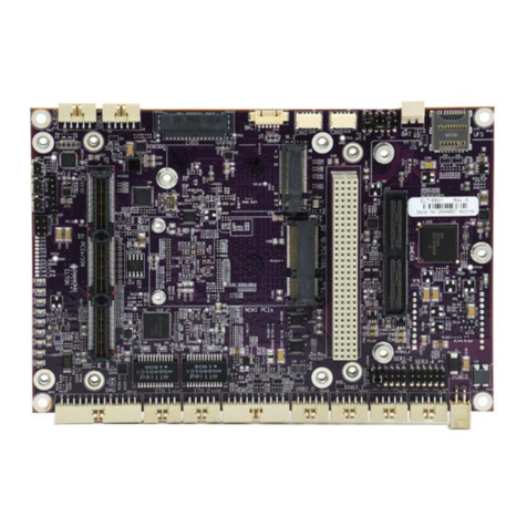
Diamond Systems FLOYD FLD-BB01 User manual

Diamond Systems
Diamond Systems Ziggy User manual

Diamond Systems
Diamond Systems ELTON ELT-BB01 User manual

Diamond Systems
Diamond Systems Jackson JAX-BB01 User manual

Diamond Systems
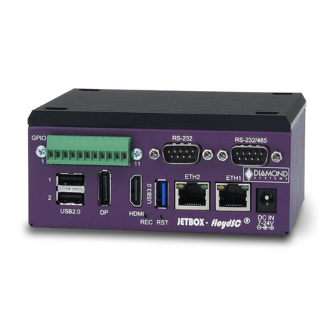
Diamond Systems JETBOX FLOYD-SC Series User manual
Popular Carrier Board manuals by other brands

Connect Tech
Connect Tech Cogswell user guide

REDEKOP
REDEKOP Actuated Tailboard installation manual

Connect Tech
Connect Tech Rogue AGX101 user guide

VIA Technologies
VIA Technologies QSM-8Q60 Design guide

ENGICAM
ENGICAM MicroGEA MX6ULL 512MB LCD Getting started manual

Guide Gear
Guide Gear 712140 Instructions for assembly and use