DiaTecne PulsePen User manual
User Manual
PulsePen
PulsePen is a device manufactured by DiaTecne s.r.l.
⚠ This manual is an integral part of the product and must be kept together with it.
!
1
User Manual PulsePen - V. 5.0_b

Index
page
Description 3
Intended Use 4
Classification 4
Patients and Users 4
Applanation Arterial Tonometry 5
Distance Measurement 6
Tonometric unit - wTn1 7
ECG unit - wEc1 7
Signal Receiver unit - wRs1 7
Technical Specifications 8
Computer Connection 9
Software Installation 9
Use of the device 10
Maintenance 13
General Precautions and Warnings 13
Mutual interference with other systems 15
Recorded values of Electromagnetic Compatibility 16
Usage Problems and Solutions 20
Useful life 21
Note on recycling 21
Symbols and Abbreviations 22
Labels 23
Various 23
!
2
User Manual PulsePen - V. 5.0_b
Description
PulsePen is an active medical device, for diagnostic purposes, intended for recording the arterial pressure
curve and evaluating the stiffness of the arteries, using the "Applanation Tonometry" method.
The PulsePen must be used by qualified medical / paramedical personnel who are familiar with the
“Applanation Tonometry” method, in medical clinics or research centers.
The primary functions are the capture, display and storage of the arterial pressure signal in order to
subsequently proceed with the calculation of the related parameters, including the pulse wave velocity
(PWV), a parameter related to the stiffness of the arteries.
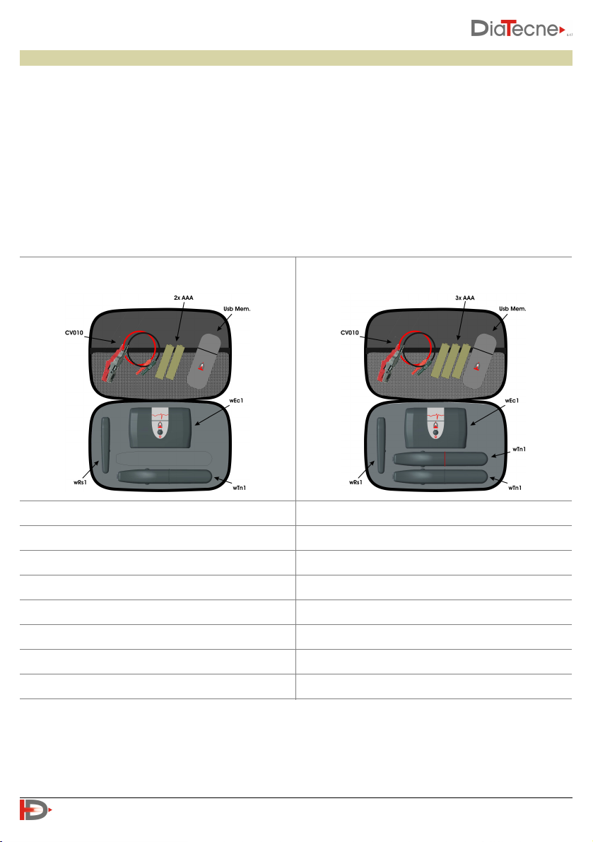
The medical device is available in two different configurations, WPP001-ET and WPP001-ETT, the
characteristics of which are shown below.
1 Tonometric unit - wTn1
2 Tonometric units - wTn1
1 ECG unit - wEc1
1 ECG unit - wEc1
1 Signal Reicever unit - wRs1
1 Signal Reicever unit - wRs1
1 ECG cable set - CV010
1 ECG cable set - CV010
2 Alkaline Batteries 1.5 V - AAA - IEC LR03
3 Alkaline Batteries 1.5 V - AAA - IEC LR03
User Manual
User Manual
Guarantee Certificate
Guarantee Certificate
USB drive
USB drive
WPP001-ETT
WPP001-ET
!
3
User Manual PulsePen - V. 5.0_b

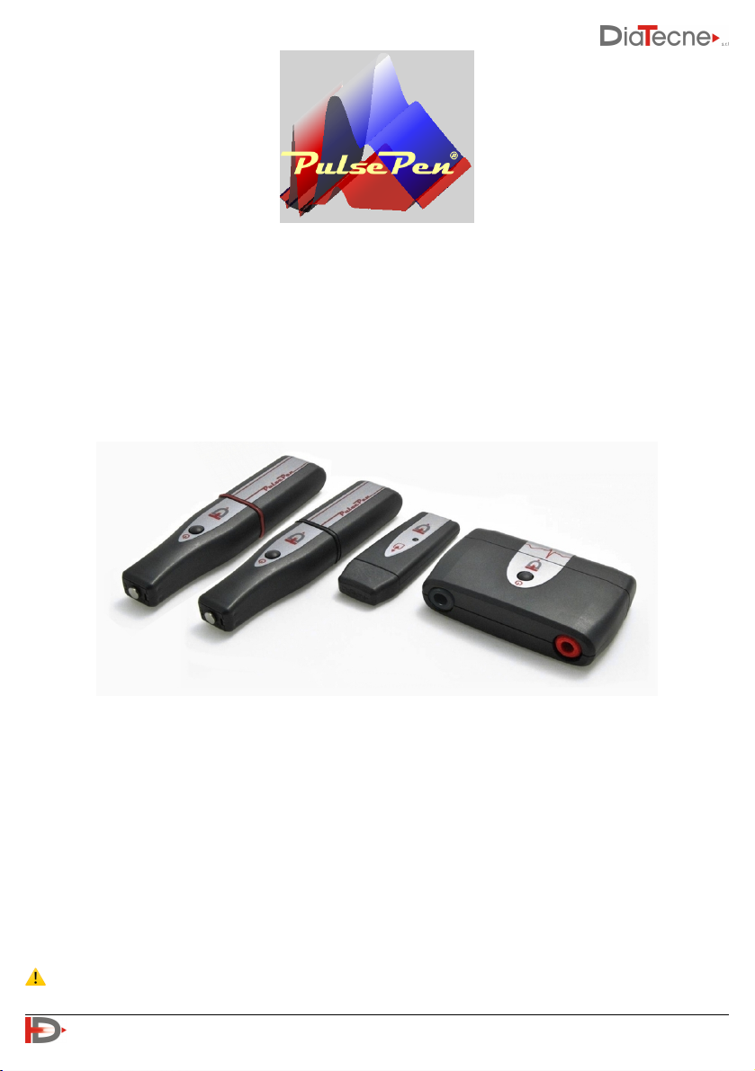
The medical device consists of the following parts:
•Tonometric unit PulsePen, code wTn1, for the capture of a pressure signal with the non-invasive
“Applanation Tonometry” method and radio transmission to wRs1. The number of such units included in
the package is one for the WPP001-ET device and two for the WPP001-ETT device.
•ECG unit, code wEc1, for the capture of one electrocardiographic lead and radio transmission to wRs1.
•Signal receiver unit, code wRs1, to be inserted in one USB port of the computer, for synchronization and
collection of signals coming from wTn1 and wEc1.
•The package includes the following accessory parts, supplied by the manufacturer:
-ECG cable set with crocodile terminals, cod. CV010.
-USB drive with Software, Quick Guide, Tutorial, User Manual in pdf format.
-Alkaline Batteries 1.5 V - AAA - IEC LR03.
-User Manual.
-Guarantee Certificate.
-Bag to carry the device with its accessories.
Below, speaking of device or instrument, we refer to all the units that compose it unless otherwise
indicated. Each unit, individually, does not provide any useful results.
The PulsePen must be connected to a computer, provided by the user, in order to view, record and
analyze signals. The connection to the computer is galvanically isolated being made via radio
through the wRs1 unit.
During the patient examination, it is necessary to input the systolic and diastolic pressure values
measured with a validated sphygmomanometer supplied by the user.
Intended Use
PulsePen is an active medical device, for diagnostic purposes, intended for recording the arterial pressure
curve and evaluating the stiffness of the arteries, using the "Applanation Tonometry" method.
Classification
Class IIa medical device according to the Regulation (EU) 2017/745.
Patients and Users
The PulsePen medical device is intended to be used with all types of patients (adults and children) who
may need it, both in a hospital setting in an inpatient ward and in an outpatient setting, or in clinical
research conditions.
The user of the medical device must be qualified medical / paramedical personnel who are familiar with
the "Applanation Tonometry" method. It is intended for use in hospitals, medical clinics or research
centers.
!
4
User Manual PulsePen - V. 5.0_b
Applanation Arterial Tonometry
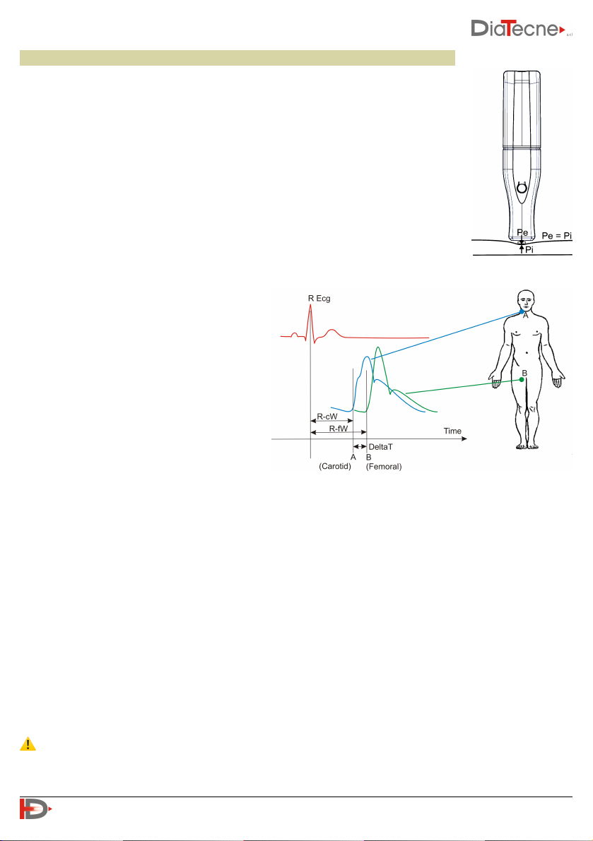
The instrument is based on the principle of "Applanation Tonometry". With this
method, the sensor is placed on the skin in correspondence with the arterial pulse,
exerting a moderate pressure: in such a way the artery is slightly compressed
(applanation tonometry) and a balance of the circumferential forces inside the
vessel is obtained. The sensor records the pressure inside the compressed artery.
Intermediate layers between sensor and vessel, with their thickness and rigidity that
vary for each individual, influence the pressure measured by the sensor in a not, a
priori, quantifiable manner. For this reason, it is necessary to calibrate the
tonometric signals using the systolic and diastolic pressures obtained from an
external sphygmomanometer (supplied by the operator). The calibration process is
based on the assumption that diastolic and mean pressure substantially don’t
change along the arterial tree.
The pulse wave velocity is defined as the
propagation velocity of the pressure wave
(not of the blood) from the center to the
periphery and is therefore obtained by
dividing the distance between two examined
points (for example Carotid and Femoral) by
the related sphygmic wave transit time
(DeltaT).
PWV = Distance (B-A) / DeltaT
PWV it is conventionally expressed in m / s
(meters / second).
The transit time of the sphygmic wave can be assessed in two different ways:
I. Using the wEc1 unit together with the wTn1 unit to measure the delay time between the R peak of the
ECG wave and the “foot” of the tonometric waves, first for the Carotid Artery (R-cW) and then for the
Peripheral Artery (e.g. the Femoral Artery in the figure, R-fW ), obtaining DeltaT, the difference
between time A and B.
II. Using two wTn1 units to contemporarily capture two tonometric signals, one of the Carotid Artery and
the other of the selected Peripheral Artery, to obtain the time interval DeltaT between the two “feet”
of the waves.
The DeltaT interval in any case is calculated automatically by the WPP001-ETT Software.
As for the distance measurement, refer to the next paragraph.
⚠ The ECG lead captured must only be used for the PWV estimation and must never be used for any
kind of diagnosis on the patient!
!
5
User Manual PulsePen - V. 5.0_b
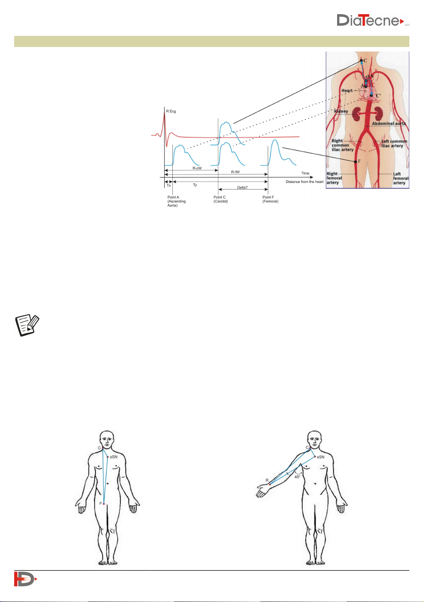
Distance Measurement
2) Subtractive Method:
This method is based on the fact that
the initial pressure wave, once it reaches the bifurcation at the suprasternal notch (sSN in the figure),
propagates both towards the Carotid and towards the Aorta. Assuming similar propagation characteristics
in the two sections, when the rising pressure wave will have arrived in C (Carotid), the descending pressure
wave will have arrived in C ', equidistant from sSN with respect to C. On the basis of these considerations,
the distance actually traveled by the pressure wave corresponding to the DeltaT delay in the example in
the figure, is equivalent to the segment C '- F and therefore distance = (sSN - F) - (C' - sSN) which can be
approximated in distance = (sSN - F) - (C - sSN).
Whichever method is chosen, it is still necessary to enter the three distances (Carotid - P_A,
sSN - P_A, Carotid - sSN) so that it is possible to calculate all parameters by the software.
!
6
User Manual PulsePen - V. 5.0_b
1) Direct Method:
The direct distance between the
Carotid (C) and the Peripheral
Artery (P_A), (F - Femoral in the
example) is measured. The result is
automatically multiplied by 0.8 by
the software, according to the
accredited guidelines.
Measurement of distances for the Femoral, Tibial,
Dorsalis Pedis Artery: A tape measure is used to
measure the distances between the Carotid Artery
and the Peripheral Artery (Femoral in the
example), between the Carotid Artery and the
suprasternal notch and finally between the
suprasternal notch and the Peripheral Artery.
Measurement of distances for the Brachial, Radial
Artery: with the arm at 45 degrees as in the figure,
a tape measure is used to measure the distances
between the Carotid and the Peripheral Artery
(Radial in the example), between the Carotid and
suprasternal notch and finally between the
suprasternal notch and Peripheral Artery.
A tape measure is used to measure the distance between the landmarks: this
can be estimated mainly in two ways, both supported by the PulsePen
Software:
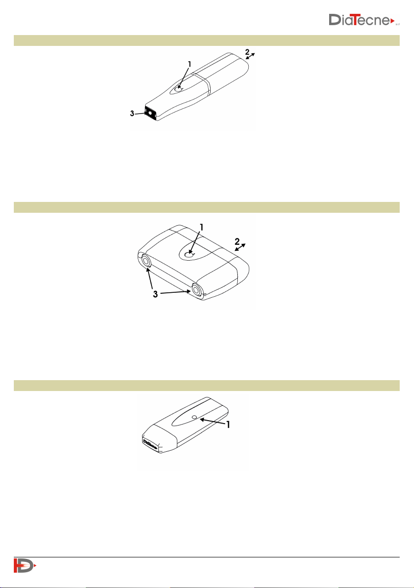
Tonometric unit - wTn1
1. On / Off button: keep pressed for about 1 sec.
2. Cap for battery replacement: pull away from the tonometer’s body. Remove the old battery pushing it
from the side opposite the opening. Insert the new battery without ever forcing and respecting the
polarity indicated by the appropriate label. Put the cap back in its seat by pushing it until clicks.
3. Active part of the tonometric sensor.
ECG unit - wEc1
1. On / Off button: keep pressed for about 1 sec.
2. Cap for battery replacement: pull away from the unit’s body. Remove the old battery. Insert the new
battery without ever forcing and respecting the polarity indicated by the appropriate label. Put the cap
back in its seat by pushing it until clicks.
3. Patient cable sockets.
Signal Receiver unit - wRs1
1. Operating mode signaling LED. This LED blinks green when the PulsePen software is not running or if
the USB driver is not properly installed. The LED is solid green during normal operations while it is red
during reprogramming / updating.
!
7
User Manual PulsePen - V. 5.0_b

Technical Specifications
General
wTn1
wEc1
Capture
16 bit
Sampling Frequency
1000 S/sec
Wireless
ISM @ 2.4 GHz
Electrical protection:
Type EN 60601-1
Degree EN 60601-1
Class II
BF
Degree of protection against penetration of
solids / liquids:
IP20
Electromagnetic Compatibility
EN 60601-1-2 :
Group 1, Class B
Operating Ambient Temperatue
from +5°C to +40°C
Transportation and Storage Temperature
from -25°C to +70°C
Relative Humidity
from 30% to 80% non-condensing
Atmospheric Pressure
from 860 to 1060 hPA
Resolution
0.004 mmHg
Dynamic range
≥ 220 mmHg
Data transmission
Wireless, ISM @ 2.4 GHz
Acoustic Signals
Power on / off
Power supply
Alkaline Battery AAA - 1.5V IEC LR03 (indicative autonomy ≥ 50 hours / ≥ 600 exams)
Max force to the sensor
4.5 Kg
Vibrations
≤ 20 g @ 10 Hz - 2 KHz sinusoidal
Shock
≤ 150 g
Weight
25 g without battery
Dimensions [mm]
114 (L) x 25 (W) x 20 (H)
Resolution
0.15 μV
Dynamic range
≥ ± 5 mV
Data transmission
Wireless, ISM @ 2.4 GHz
Acoustic Signals
Power on / off
Power supply
Alkaline Battery AAA - 1.5V IEC LR03 (indicative autonomy ≥ 50 h / ≥ 600 exams)
Vibrazioni
≤ 20 g @ 10 Hz - 2 KHz sinusoidal
Shock
≤ 150 g
Weight
36 g without battery
Dimensions [mm]
49 (L) x 75 (W) x 21 (H)
!
8
User Manual PulsePen - V. 5.0_b

wRs1
CV010
Computer (recommended configuration)
Computer Connection
The connection of the WPP001-ET / WPP001-ETT device to the computer
is done through the wRS1 unit, by inserting it into a USB 1.0 / 2.0 - type A port:
Software Installation
The PulsePen system includes two software (x.x.x means the version):
•WPulsePen (WPP001-ETT- x.x.x): full-featured software for the capture, display, storage, and analysis of
signals with the calculation of the parameters. It includes the patient database management and works
on signals up to 10 ECG/ tonometric complexes. It’s also possible to make long-term signal records (see
the online Help). This software allows for the generation of a patient report, the content of which must
always be verified by a physician expert in the method. DiaTecne s.r.l. takes no responsibility for the final
diagnosis.
•WPulsePen-LP (WPP001 LP-ETT- x.x.x): software for capturing, displaying and saving long-term signals. It
does not perform signal analysis or patient database management.
To install the software included in the supplied USB drive, proceed by following the instructions given in
the “readme.txt” file: both the WPulsePen and WPulsePen_LP software will be installed, with their icons
on the desktop and the USB drivers for the wRs1 receiver. Refer to "Usage Problems and Solutions" if you
have difficulty.
The “Arial” font should be installed on the computer for a correct representation of the text.
PC connection
USB 1.0 / 2.0 - type A
Data transmission
Wireless, ISM @ 2.4 GHz
LED
Operating mode signaling
Power supply
< 50 mA @ 5V, powered by the USB connector of the P.C.
Weight
12 g
Dimensions [mm]
67 (L) x 25 (W) x 11 (H)
Terminals
Universal for tab, clip, press-stud ECG electrodes
Connettors
DIN 42802 compliant
Clock Frequency
≥ 2GHz
Ram
≥ 2 GB
Free Hard Disk space
≥ 4.5 GB (SW + Database)
Graphic Resolution
≥ 1280 x 800, 24 bit color
Operating System
Windows® XP SP2/3, Vista, 7, 8, 10 - 32/64 bit
USB ports
≥ 1
Safety
EN 60950-1 and later compliant
!
9
User Manual PulsePen - V. 5.0_b
Use of the device
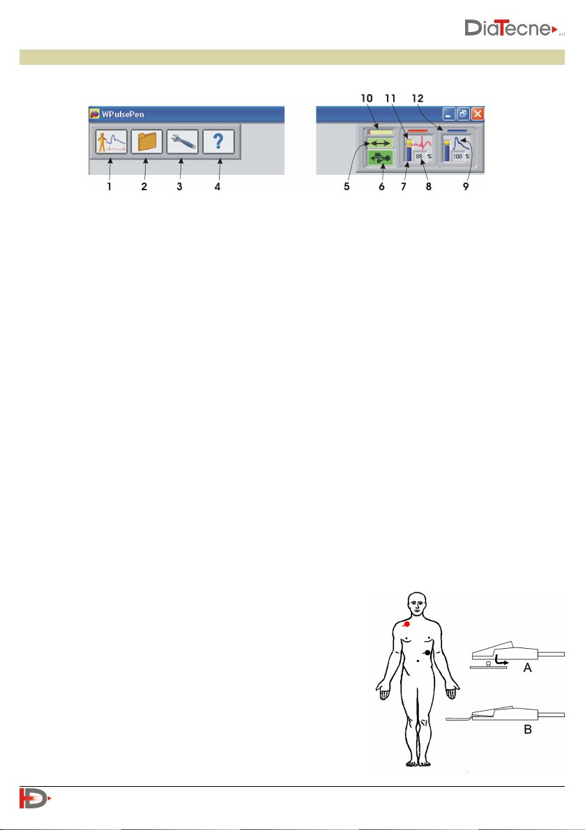
Software Interface
1. New examination.
2. Access to the Patient Archive.
3. Setup and device programming.
4. “On line” instructions (Help / Quick Guide / Tutorial / Manual).
5. Data exchange between computer and wRs1 (green under normal conditions).
6. USB drive wRs1 connection (green if recognized correctly).
7. Graphic indication of the residual battery capacity of wEc1 and wTn1.
8. Remaining battery capacity of wEc1 and wTn1: replace the battery if less than 10%.
9. Icon representing the ECG (QRS) or Tonometric (pressure wave) signal depending on the type of active
sensor.
10. Data coming from wRs1 waiting to be processed: a short bar signals a better situation to a long bar (it
depends on the speed of the computer, other running programs,…).
11. The positive terminal of the battery symbol turns yellow in standby, i.e. when the “Freeze” is active or
in situations other than that of “real time” acquisition and display of signals.
12. Sensor1 corresponds to the red trace (ECG or Tonometer) while Sensor2 corresponds to the blue trace
(Tonometer only).
Preparation for the exam
A. Start the WPulsePen software.
B. Insert the wRS1 receiver into a USB port and wait for the device to be recognized (fig. 1 - icons 5 and 6
green).
C. Extract the cap of the wEc1 and wTn1 units, insert the batteries in the appropriate compartment,
strictly respecting the orientation indicated (see Warnings)
and put the cap back in its seat.
D. Let the patient lie down on the couch.
If you intend to carry out the examination with two tonometers
at the same time, go directly to the next point "H".
E. Using "fresh" gel-embedded disposable Ag / AgCl ECG
electrodes, for crocodile clips, place them in the following
way:
•Red: right subclavian region
•Black: left subcostal region
!
10
User Manual PulsePen - V. 5.0_b
fig. 2
fig. 1

The suggested position can be changed at the operator’s discretion in the presence of ECG signals that are
too small, inverted or altered, for example due to pathologies. Direct contact of the electrodes with
synthetic clothing which could cause disturbance must be avoided, in which case it is advisable to
interpose a sheet of paper.
F. Connect the crocodiles of the patient cable to the respective electrodes according to their type (type A
or type B, see fig. 2)
G. Insert the connectors of the opposite end of the ECG cable into the corresponding sockets of wEc1.
H. Turn on the units you intend to use (wEc1 and wTn1 or two wTn1) holding down the on / off button
until you hear a beep (after about 1 sec). wEc1 produces a single “beep” as well as wTn1 programmed
as Sensor1 (red trace) while wTn1 programmed as Sensor2 (blue trace) produces two “beeps”.
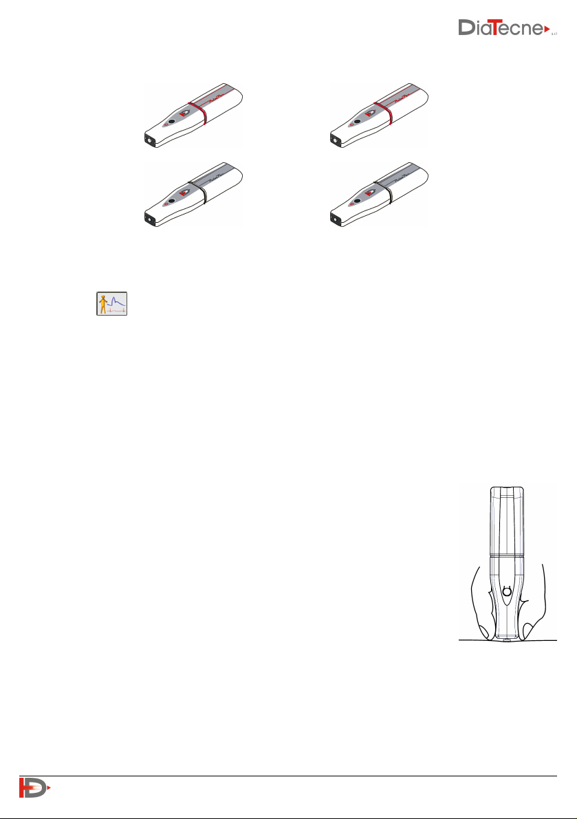
Permitted Sensor Combinations
The correct use of modules wEc1 and wTn1 is based on the assumption that one of the two is set as
Sensor1 and the other as Sensor2: wEc1 is always set as Sensor1 and cannot be changed while wTn1 can
be set in two ways: refer to the Help online of the software for operating instructions.
wEc1 - Sensor1 (1 beep when switched on) + wTn1 set as Sensor2 (2 beeps when switched on). These are
the factory settings for the WPP001-ET system and for the wTn1 unit with the black ring of the WPP001-
ETT system:
✔ +
wTn1 set as Sensor1 (1 beep when switched on) + wTn1 set as Sensor2 (2 beeps when switched on). These
are the factory settings respectively for the wTn1 unit with red and black ring of the WPP001-ETT system:
✔ +
Wrong Sensor combinations
wEc1 - Sensor1 (1 beep when switched on) + wTn1 set as Sensor1 (1 beep when switched on):
✘ +
!
11
User Manual PulsePen - V. 5.0_b
Both wTn1 modules set as Sensor1 (1 beep when switched on) or as Sensor2
(2 beeps when switched on):
✘ +
✘ +
Carrying out the exam
The functionalities below concern the Sw WPulsePen, of which the Sw WPulsePen_LP is a simplified
version.
Select the icon to start a new exam and choose a patient from those already in the archive or insert
the data of a new patient, such as name, surname, date of birth, gender: at this point the keys
corresponding to the various arteries will be enabled. Selecting the desired one a new screen will open
where the acquired signals will be displayed once the wTn1 probe(s) has(have) been positioned on the
region to be explored. An automatic signal "Freeze" function stops the acquisition when no activity is
detected on the wTn1-Sensor2 tonometer (blue trace). The operator must firmly rest his elbow and hold
the wTn1 probe as shown in fig. 3 with the fingertips in contact with the patient's skin, thus minimizing
tremors. The probe should be held perpendicular to the skin and not tilted. It is advisable to consult the
Quick Guide contained in the Help-Tutorial. With the PulsePenHolder accessory, stable signals are obtained
without the operator's tremor. Once a series of overlapping complexes has been obtained, indicated by the
green color of the traffic light at the top of the screen (see the software Help), the
operator can interrupt the acquisition by lifting the wTn1-Sensor2 tonometer. By
pressing the icon with the disk symbol or the Enter key, the last heart complexes
recorded, up to a maximum of ten, are automatically saved and analyzed. At this
point, a window will appear for entering the systolic and diastolic pressure
measured immediately before, during or after, with an external
sphygmomanometer. In the case of a peripheral Artery, the operator will also have
to use a meter to obtain three distances, in millimeters: Carotid - Peripheral Artery,
Carotid - Suprasternal notch and SupraSternal notch - Peripheral Artery.
In the estimation of PWV this allows to apply both methods of distance evaluation
suggested by the international guidelines, i.e. both the “direct method” and the
“subtractive method” - see the relevant paragraph.
At this point a new panel will show the parameters automatically calculated by the
software.
Refer to the online Help for all the additional features available.
!
12
User Manual PulsePen - V. 5.0_b
fig. 3

Patient database
The WPulsePen software manages the patient database called “WPPArch.dbd” which is located in the
“WPulsePen_Data” folder. Selecting the icon the list of all patients is shown with their registered
exams from which you can choose the one to be displayed on the screen. Patients can also be organized in
various subfolders at the operator's discretion (by type, pathology, ...).
Import and export functions in different formats are also available.
The WPulsePen_LP software records the individual exams on text files (* .txt) contained in the “ASCII”
subfolder of the “WPulsePen_Data” folder.
Support features
The icon allows you to access the panel which offers the possibility to select the language, format of
date, program devices, etc ...
The icon allows you to access the online Help.
Shutdown
•To turn off the wEc1 and wTn1 Sensors, press and hold the on / off button until you hear a beep (after
about 1 sec in normal mode - about 3 secs in programming mode).
•The wEc1 and wTn1 units turn off automatically when the program is exited or if there is no connection
with the wRs1 unit for more than 30 seconds, for example if the WPulsePen software is not running or
the distance between the units is excessive. The Sensors also turn off automatically if they remain in
standby for more than 10 minutes to preserve the battery: in fact, the stay in standby presupposes no
acquisition of signals during this interval and therefore the inactivity of the Sensors.
The wEc1 and wTn1 units do not transmit radio frequency until the connection with wRs1 is
established.
Maintenance
No particular maintenance operations or periodic calibration of the instrument are necessary.
General Precautions and Warnings
⚠ It is very important to read the following warnings carefully before using the device. Improper use
can have very serious consequences.
•In case of prolonged non-use, remove the batteries from wEc1 / wTn1.
•Before use, the metal disc of the wTn1 probe, the CV010 patient cable and the device casing must be
cleaned with a soft, clean and dry cloth or slightly soaked in alcohol.
•Pay close attention so that alcohol, other liquids and dust do not penetrate inside the wTn1 probe or
other units because this could cause serious problems, irreparably damaging the internal parts.
!
13
User Manual PulsePen - V. 5.0_b

•CV010 Patient cables are thin and flexible for improved handling. It is necessary to avoid both tugging
and bending them at a sharp angle so as not to damage them.
•This device is intended exclusively for use by medical / paramedical personnel in a medical environment.
•Do not use the device in the operating room and in any case in the presence of flammable gases /
substances.
•Do not use the device for intracardiac applications or in direct contact with internal parts of the body.
•The processing of the recorded data and the diagnosis are exclusive to the doctor.
•Do not sterilize the device either in an autoclave or with liquid substances.
•Do not subject the pressure sensor of the wTn1 probe to mechanical shocks such as bumps or falls.
•Keep the wTn1 and wEc1 units, with its patient cable, at a distance from the computer no less than 1.5
meters and the computer itself at a distance of no less than 1.5 m from the patient.
•Avoid touching any part of the computer at the same time, including the wRs1 unit, and one or both
units wEc1 (with its patient cable) and wTn1.
•Do not immerse any part of the device in water or other substances or subject it to splashes. Never use
Gel on the wTn1 pressure probe.
•Do not carry out maintenance on the device that involves opening it; in case of device malfunction
contact DiaTecne s.r.l.
•If there are any abrasions, breaks in the sheath or any defect in the CV010 patient cable, use of the
device must be immediately suspended and the defective part sent to DiaTecne s.r.l. for repair /
replacement.
•Do not use the device in case of breakage of any part, do not proceed with repair attempts but contact
DiaTecne s.r.l. for repair / replacement.
•Do not make any modifications of any kind to the device and do not use any accessories other than those
supplied.
•Keep the wTn1 tonometric probe and the CV010 patient cable terminals away from power outlets and
surfaces where potentially dangerous voltages are present.
•Use a battery-powered computer (laptop) or alternatively a mains-powered computer that complies with
current medical standards.
•Use the device away from electromagnetic interference sources such as for example “cordless”
telephones operating at radio frequency, cellular phones, Bluetooth and WiFi devices or other devices
that emit high frequency electromagnetic waves.
•During the examination, keep the wEc1 unit at least 20 cm from the patient and operator and limit the
duration of contact of the wTn1 unit with the patient and operator to the time necessary to perform the
exam: all this to reduce electromagnetic radiation exposure due to the transmission of signals via radio,
even if they are of very low intensity.
•Use only 1.5V batteries of the indicated type. Insert them as shown and check their condition before
each use (dead or damaged batteries can cause acid leakage).
•Do not turn on or use the device if the battery compartment caps are not properly closed.
•Connect the CV010 patient cable connectors only to the corresponding sockets of the wEc1 unit. Do not
make any different types of connections to these connectors.
•The device must never be used together with a defibrillator as it was not designed for this use.
•During the recording of the carotid pressure curve, compression of the carotid bulbs could accidentally
induce a reduction in heart rate. This phenomenon may be more pronounced in elderly patients with
accentuated vagal sensitivity. It is strongly recommended that the examination be interrupted when
!
14
User Manual PulsePen - V. 5.0_b

bradycardia occurs. It should also be remembered that simultaneous compression of the carotid bulbs
must be avoided, as it can cause syncope due to arterial hypotension or severe bradyarrhythmias.
•The software allows for the generation of a patient report, the content of which must always be verified
by a physician expert in the method. DiaTecne s.r.l. assumes no responsibility for the final diagnosis.
•Install anti-virus software on the computer used with the PulsePen system.
•Periodically make backup copies of the patient archive as described in the software's online Help.
DiaTecne s.r.l. assumes no responsibility for the loss of data in the archive.
•Reduce the likelihood of radio interference occurring. Make sure that the WiFi and Bluetooth of the
computer and mobile phones are turned off while using the PulsePen or alternatively activate the
'airplane mode' on these devices.
•If it is not possible to activate 'airplane mode' on the computer and / or turn off WiFi and Bluetooth, use
a USB extender cable to connect the wRs1 unit, in order to keep the latter away from the computer itself.
•In the event of adverse events and / or serious accidents involving the medical device, the user is
required to notify the manufacturer and the competent authorities of his Country.
•Use the device only for the purposes specified in this manual.
•DiaTecne s.r.l. cannot be held responsible for damage caused to people, animals or things in the event
that the user does not scrupulously follow the instructions given in this manual.
Mutual interference with other systems
The PulsePen device has been designed to be immune to electrical, electromagnetic, electrostatic and
magnetic disturbances, normally present; similarly, the PulsePen produces a reduced quantity of
disturbances towards the other devices. However, it cannot be excluded that, in particular situations, there
may be operating anomalies also in the form of signal alteration: in this case it is necessary to remove all
potential sources of disturbance when possible or move to a more appropriate location. Considering the
"Intended use" of the device that requires a qualified medical operator, the latter can easily recognize an
abnormal operating situation, such as the presence of "noise" superimposed to the signal or alteration of
the morphology of the signal and follow the instructions suggested above.
Typical sources of disturbance are “hotspots” / WiFi devices, Bluetooth / Zigbee devices and any type of
transmitter in the 2.4 GHz frequency band.
⚠ Make sure that the WiFi and Bluetooth of the computer and mobile phones are turned off while
using the PulsePen or alternatively activate the 'airplane mode' on these devices.
•Electromedical devices require special precautions for electromagnetic disturbances (EMC) and must be
installed in accordance with the information in the following tables.
•Mobile radio frequency communication devices can disturb electromedical devices.
•For the correct functioning of the PulsePen device, the wEc1 and wTn1 units must be within a radius of 3
meters from the wRs1 unit. Greater distances may cause incorrect operation.
•The use of cables and accessories other than those supplied could adversely affect the performance of
the device.
•Respect the distances from other devices according to the following Tab. 4.
•The PulsePen device transmits radio frequency in the 2.4 GHz ISM band with MSK modulation, ERP = 2
dBm (P ≈ 1.6 mW).
•The PulsePen system meets the requirements indicated in the following tables.
!
15
User Manual PulsePen - V. 5.0_b

Recorded values of Electromagnetic Compatibility
Tab. 1: Reference and Declaration of Manufacturer - Electromagnetic Emissions
The PulsePen is suitable for use in the specified electromagnetic environment. The user of the PulsePen should
assure that it is used in an electromagnetic environment as described below.
Emissions tests
Compliance
Electromagnetic Environment
RF Emissions
CISPR 11
Group 1
The PulsePen uses RF energy only for its internal function.
Therefore, the RF emission is very low and not likely to cause any
interference in nearby electronic equipment.
RF Emissions
CISPR 11
Class B
The PulsePen is suitable for use in all establishments, including
domestic establishments and those directly connected to the
public low-voltage power supply network that supplies buildings
used for domestic purposes.
Harmonic Emissions
IEC 61000-3-2
Not Applicable
Voltage fluctuations /
Flicker Emissions
IEC 61000-3-3
Not Applicable
!
16
User Manual PulsePen - V. 5.0_b

Tab. 2: Reference and Declaration of Manufacturer - Electromagnetic Immunity
The PulsePen is suitable for use in the specified electromagnetic environment. The user of the PulsePen should
assure that it is used in an electromagnetic environment as described below.
Immunity
Test
IEC 60601-1-2
Test leve l
Compliance level
Electromagnetic Environment
Electrostatic
Discharge (ESD)
IEC 61000-4-2
+/- 8KV contact
+/- 2KV, +/- 4KV,
+/- 8KV, +/- 15KV air
+/- 8KV contact
+/- 2KV, +/- 4KV,
+/- 8KV, +/- 15KV
air
Floors should be wood, concrete or ceramic
tile. If floors are covered with synthetic
material, the relative humidity should be at
least 30%.
Electrical Fast
Transient / Burst
IEC 61000-4-4
±2 KV
Frequency 100 kHz
Not Applicable
Mains power quality should be that of a typical
commercial or hospital environment.
Surge
IEC 61000-4-5
+/- 0.5KV, +/- 1KV
differential mode
+/- 0.5KV, +/- 1KV, +/-
2KV common mode
Not Applicable
Mains power quality should be that of a typical
commercial or hospital environment.
Voltage dips, short
Interruptions
and Voltage
variations on power
supply input lines
IEC 61000-4-11
Voltage dips
0% UT , 0.5 cycles
@ 0°, 45°, 90°, 135°,
180°, 225°, 270°, 315°
0% UT , 1 cycle /
70% UT , 25/30 cycles,
Single phase @ 0°
Voltage interruptions
0% UT , 250/300 cycles
Not Applicable
Mains power quality should be that of a typical
commercial or hospital environment. If the
user of the PulsePen requires continued
operation during power mains interruptions, it
is recommended that the computer used with
the PulsePen be powered from an
uninterruptible power supply or a battery.
Magnetic Field at
Power frequency
(50/60 Hz)
IEC 61000-4-8
30 A/m
50 Hz or 60 Hz
30 A/m
50 Hz or 60 Hz
Power frequency magnetic fields should be at
levels characteristic of a typical location in a
typical commercial or hospital environment.
!
17
User Manual PulsePen - V. 5.0_b

Tab. 3: Reference and Declaration of Manufacturer - Electromagnetic Immunity
The PulsePen is suitable for use in the specified electromagnetic environment. The user of the PulsePen should
assure that it is used in an electromagnetic environment as described below.
Immunity
Test
IEC 60601-1-2
Test leve l
Compliance level
Electromagnetic Environment
Conducted RF
EN 61000-4-6
from 150 kHz to 80
MHz
Home Healthcare
Environment
3 V RMS outside the
ISM band, 6 V RMS in
the ISM and amateur
radio bands
Professional
Healthcare
Environment
3 V RMS outside the
ISM band, 6 V RMS in
the ISM band
Not applicable
Radiated RF
EN 61000-4-3
3 V/m
80 MHz to 2,7 GHz
80% AM at 1kHz
3 V/m
80 MHz to 2,7 GHz
80% AM at 1kHz
Portable and mobile RF communications
equipment should be used no closer to any
part of the PulsePen, including cables, than the
minimum recommended separation distance
calculated from the equation applicable to the
frequency of the transmitter.
Recommended separation distance:
d= 1,2√P 150kHz to 80 MHz
d= 1,2√P 80MHz to 800 MHz
d= 2,3√P 800MHz to 2,5GHz
Where P is the maximum output rating of the
transmitter in watts (W) according to the
transmitter manufacturer and d is the
recommended separation distance in meters
(m).
Field strengths for fixed RF transmitter, as
determined by an electromagnetic site survey,
should be less than the compliance level in
each frequency range.
Levels characteristic of a typical commercial /
hospital environment.
Interference may occur in the vicinity of
equipment marked with the following symbol:
!
18
User Manual PulsePen - V. 5.0_b

Tab. 4: Recommended separation distances between portable / mobile RF communications equipment
and the PulsePen
The PulsePen is intended to be used in an electromagnetic environment in which radiated RF disturbances are
controlled. The user of the PulsePen can help prevent electromagnetic interference by maintaining a minimum
distance between portable / mobile RF communication equipments (transmitters) and the PulsePen as recommended
below, according to the maximum output power of the communications equipment.
Rated maximum output power
of the transmitter
(W)
Separation distance according to frequency of transmitter
m (meters)
from 150 kHz to 80 MHz
d = 1,2 P
from 80 MHz to 800 MHz
d = 1,2 P
from 800 MHz to 2,5 GHz
d = 2,3 P
0,01
0,12
0,12
0,23
0,1
0,38
0,38
0,73
1
1,2
1,2
2,3
10
3,8
3,8
7,3
100
12
12
23
For transmitters rated at the maximum output power not listed above, the recommended separation distance d in
meters (m) can be estimated from the equation applicable to the frequency of the transmitter, where P is the
maximum output power rating of the transmitter in watts (W) according to the transmitter manufacturer.
at 80MHz and 800MHz, the separation distance for the higher frequency range applies.
These guidelines may not apply in all situations. Electromagnetic propagation is affected by absorption and
reflection from structures, objects and people.
!
19
User Manual PulsePen - V. 5.0_b

Usage Problems and Solutions
Check and implement the following suggestions, from top to bottom, until the problem is solved.
The software installation does not complete:
•The installation of the software requires the operator to have the necessary permissions: in a hospital or
research setting it is often necessary to contact the system administrator to proceed.
The wEc1 / wTn1 unit does not turn on (no beeps):
•Check that the battery is the required type, inserted with the correct orientation, and that it is fresh.
•Keep the On / Off button pressed until the acoustic signal is heard (after about 1 sec).
•Remove and reinsert the battery.
There are no signals to the computer:
•fig. 1 - icon 6 red: in this case the USB receiver - wRs1 has not been recognized.
-Close the software, remove and reinsert the wRs1 signal receiver and restart the software.
-If the problem persists, it is recommended that you check with your system administrator that access
to the computer's USB ports is not inhibited. Make sure that the presence of computer protection
software such as Antivirus, Firewall, etc., does not prevent access to external USB devices.
-With wRs1 inserted, launch “DrvInst.exe” in the folder .. \ Program Files (x86) \ WPulsePen or manually
reinstall the USB drivers that are contained in the folder “wRs Usb Driver” if the problem has not been
solved with the previous suggestions.
•fig.1 - icon 6 green and icon 5 red: the wRs1 unit is recognized correctly but the firmware in it installed is
not compatible with the version of the software running on your computer.
-Update firmware and / or software to the latest version. Contact DiaTecne s.r.l. in case of doubts or
problems.
•fig.1 - icons 5 e 6 both green but icons 12 (red and blue) inactive: the wEc1 / wTn1 units do not connect.
-Check that the wEc1 / wTn1 units are turned on (acoustic signal at power on).
-It is necessary that the radio channel of all units wRs1, wEc1, wTn1 is the same and that the relative
firmware are compatible: go to the "settings" panel of the software (fig. 1 - icon 3), select the
programming mode and follow the instructions in the online Help of the software to put the involved
wRs1, wEc1, wTn1 units in programming mode, one at a time, in order to verify and eventually update
what is required. Contact DiaTecne s.r.l. in case of doubts or problems.
•fig.1 - icons 5 e 6 both green and icons 12 (red and blue) active: the system is in “Freeze” mode due to
the absence of tonometric signal on the wTn1 probe - sensor 2 (blue trace).
-Gently touch the pressure sensor with your fingers.
If it is not possible to solve the problems listed independently or if there are doubts about the operation of
the device, please contact DiaTecne s.r.l. at the following email address: [email protected]. Assistance
will be provided as soon as possible.
!
20
User Manual PulsePen - V. 5.0_b
Other manuals for PulsePen
2
Table of contents
Other DiaTecne Medical Equipment manuals


Popular Medical Equipment manuals by other brands


Getinge
Getinge Arjohuntleigh Nimbus 3 Professional Instructions for use

Mettler Electronics
Mettler Electronics Sonicator 730 Maintenance manual

Pressalit Care
Pressalit Care R1100 Mounting instruction

Denas MS
Denas MS DENAS-T operating manual

bort medical
bort medical ActiveColor quick guide

AccuVein
AccuVein AV400 user manual


