DiaTecne PulsePen User manual
User Manual
PulsePen
PulsePen is a device manufactured by DiaTecne s.r.l.
This manual is an integral part of the product and must be kept together with it.
!
1
User Manual PulsePen - V. 5.2

Index
page
1. Description 3
2. Intended Use 4
3. Classification 4
4. Patients and Users 5
5. Principle of Operation 5
6. Pulse Wave Velocity 6
7. Distance Measurement 7
8. Arterial Stiffness 8
9. Clinical Benefit 9
10. Operational Setup 10
11. Signal Receiver unit - wRs1 10
12. ECG unit - wEc1 10
13. Tonometric unit - wTn1 11
14. Ecg Cable Set: CV010 11
15. Software 11
16. Method of Use 12
17. Commisioning 17
18. Placement 17
19. Maintenance and Cleaning 17
20. Usage Problems and Solutions 17
21. Mutual interference with other systems 18
22. Technical Specifications 19
23. General Precautions and Warnings 23
24. Recorded values of Electromagnetic Compatibility 25
25. Useful Life 29
26. Disposal 29
27. Symbols and Abbreviations 30
28. Labels 31
29. Various 31
!
2
User Manual PulsePen - V. 5.2

1. Description
The Medical Device (MD) object of this technical documentation is the "PulsePen", in the two available
configurations as defined below. PulsePen is an active medical device, for diagnostic purposes, intended
for recording the arterial pressure curve and evaluating the stiffness of the arteries, using the non-invasive
method of "applanation tonometry".
The primary functions are the capture, display and storage of the arterial pressure signal in order to
subsequently proceed with the calculation of the related parameters, including the pulse wave velocity
(PWV), a parameter related to the stiffness of the arteries.
With this method, the sensor, which is part of the tonometric unit, also called the "tonometric sensor", is
placed on an intact skin surface in correspondence with the arterial pulsation, exerting a modest pressure:
the artery is consequently slightly compressed (applanation tonometry) and there is a balance between
the circumferential forces inside the vessel. In this way the sensor records the pressure inside the
compressed artery.
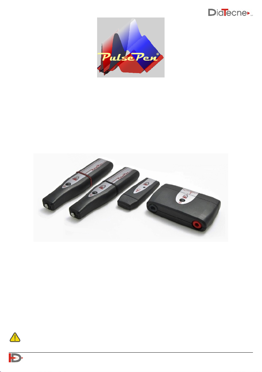
The medical device is available in two different configurations - REF: WPP001-ET and REF: WPP001-ETT, as
shown below:
1 Tonometric Unit: wTn1
2 Tonometric Units: wTn1
1 ECG Unit: wEc1
1 ECG Unit: wEc1
1 Signal Receiver Unit: wRs1
1 Signal Receiver Unit: wRs1
1 Ecg Cable Set: CV010
1 Ecg Cable Set: CV010
USB Memory with the WPulsePen Software
USB Memory with the WPulsePen Software
2 Batteries: AAA - Alkaline 1.5 V - IEC LR03
3 Batteries: AAA - Alkaline 1.5 V - IEC LR03
1 Case
1 Case
WPP001-ET
WPP001-ETT
!
3
User Manual PulsePen - V. 5.2

The MD consists of the following parts:
•PulsePen tonometric unit, from which the entire device takes its name, REF: wTn1, intended for the
acquisition of the pressure signal with the non-invasive method of "applanation tonometry" and
transmission via radio to wRs1. The number of such units included in the package varies from one, in the
case of the configuration WPP001-ET, to two in the case of the configuration WPP001-ETT.
•ECG unit, REF: wEc1, intended for the acquisition of an electrocardiographic lead and transmission via
radio to wRs1.
•Signal Receiver Unit, REF: wRs1, to be inserted in a computer USB port, intended for synchronization and
reception of signals coming from wTn1 and wEc1.
•ECG cable set with “crocodile” terminals, REF: CV010.
•USB Memory with Software, REF: WPulsePen.
The package includes the printed copy of the User Manual and the Guarantee Certificate.
Below, speaking of “device”, we refer to all the units that compose it unless otherwise indicated. Each unit,
individually, does not provide any useful results.
The AAA - Alkaline 1.5 V - IEC LR03 batteries are supplied together with the MD solely for the
purpose of allowing immediate use upon receipt of the package. These are readily available and
very commonly used batteries. It is the user's responsibility to replace them when the residual
capacity reported by the PulsePen software is less than 10%.
The PulsePen must be connected to a computer, provided by the user, in order to view, record and
analyze the signals. The connection to the computer is galvanically isolated as it is made via radio
through the wRs1 unit.
To calibrate the device, the systolic and diastolic pressure measurements taken with a user-supplied
sphygmomanometer must be manually entered on the computer.
User-supplied disposable ECG electrodes must be used for ECG acquisition. The electrocardiogram is
acquired exclusively to define the R wave to be used as a time reference for calculating the "transit
time" of the pressure wave and not for making electrocardiographic diagnoses on the patient.
2. Intended Use
PulsePen is an active medical device, for diagnostic purposes, intended for recording the arterial pressure
curve and evaluating the arterial stiffness, using the "Applanation Tonometry" method. The above device is
not a sterile device.
3. Classification
Class IIa medical device according to the Regulation (EU) 2017/745.
!
4
User Manual PulsePen - V. 5.2

4. Patients and Users
The use of the device is indicated in all age groups. Subjects at risk for premature vascular aging, young
people with isolated systolic hypertension and adults at cardiovascular risk.
Patient selection criteria:
Subjects of all ages at risk for premature vascular aging.
Young subjects with isolated systolic hypertension.
Cardiovascular risk subjects in which subclinical vascular damage is hypothesized.
Pregnancy and breastfeeding are not a contraindication to the use of the device.
The neonatal age does not constitute a contraindication to the use of the device.
The user of the medical device is exclusively a professional user to be identified in personnel with a degree
in medicine and surgery / master's degree in nursing sciences or equivalent qualifications in various
countries, who are familiar with the "applanation tonometry" method. It is intended for use in hospitals,
medical clinics or research centers.
It is not considered necessary to provide specific training for users, as the User Manual contains all the
instructions for use.
5. Principle of Operation
The operation of the medical device is based on the method of "applanation tonometry" which consists in
exerting a slight pressure on a superficial artery from the outside, so that the artery flattens itself slightly
against rigid or semi-rigid structures (bone , muscle, ...) below. In an ideal equilibrium situation (left figure)
the internal arterial pressure (Pi) is equal to the external one (Pe). The pressure is detected by a sensor
placed at the end of the wTn1 Unit, which is also called "tonometric probe" or "tonometer" in the rest of
the documentation. The pressure signal obtained from the sensor, appropriately amplified and digitized, is
continuously acquired by the wTn1 Tonometric unit and graphically presented to the user on the computer
screen to which the medical device is connected.
In the real situation, it is necessary to consider the
presence of the skin and the superficial layers between the
sensor and the artery under examination (indicated with
Skin in the figure): in this case the internal arterial pressure
(Pi) is different from the external one (Pe). In fact, to
flatten the artery it is necessary to exert an extra pressure
from the outside that deforms the skin and the
intermediate layers and furthermore the pulsatory
pressure inside the artery is transmitted outwards
attenuated by the intermediate layers themselves.
The mechanical characteristics of the skin, such as
elasticity, thickness, consistency, ..., vary from patient to
patient, with age, etc. and it is for this reason that a
transcutaneous arterial tonometer is not able to establish
the exact values of the systolic and diastolic blood pressure while preserving an identical morphology of
the pressure curve.
Consequently, it is necessary to carry out a calibration at each examination using a traditional
!
5
User Manual PulsePen - V. 5.2

sphygmomanometer that must be provided by the user. This sphygmomanometer must be a certified
medical device according to Directive 93/42/EEC or to the MDR Regulation.
Calibration: the calibration of the acquired pressure values is
based on the fact that the mean arterial pressure remains
unchanged along the entire arterial tree, from the ascending
aorta to the peripheral arteries, and also the difference between
the values of the diastolic arterial pressure between the center
and the periphery of the arterial system is insignificant (generally
between 0.2 and 0.6 mmHg in the brachial artery relative to the
ascending aorta). On the other hand, the value of the systolic
pressure increases moving from the aorta towards the peripheral
arteries due to the reflected waves (phenomenon of
amplification).
The mean arterial pressure of the sphygmic wave is defined, for
each cardiac cycle, by the integral of the pressure curve, that is, the area it subtends. That said, the mean
arterial pressure is calculated from the brachial systolic and diastolic blood pressure values measured with
a traditional sphygmomanometer, immediately before or after recording with transcutaneous tonometry
and entered manually by the user. Since the mean and diastolic pressure values are the same in the center
and periphery, the difference between mean and diastolic pressure will also be constant. The software of
the medical device, based on a simple equation, provides the value in mmHg of the arterial systolic
pressure, knowing the value in mmHg of the difference between mean and diastolic pressure and the
binary coding corresponding to the digitized signal.
6. Pulse Wave Velocity
The pulse wave velocity (PWV) is defined as the ratio between the length of the arterial segment under
examination (A-B in the figure) and the time taken by the pressure wave to travel through it: PWV =
Distance / DeltaT (not to be confused
with the speed of blood flow). There
are two ways to determine PWV:
1) By making two sequential recordings
in the carotid artery and in the selected
peripheral artery using the R wave of
the ECG as a time reference. It is
therefore obtained the delay of the
pressure wave recorded in the carotid
artery with respect to the R wave of
the ECG (R-cW) and the delay of the
peripheral pressure wave (the example
shows a femoral artery) with respect to
the R wave of the 'ECG (R-fW). The difference between R-fW and R-cW represents the DeltaT which is
the "transit time" of the pressure wave in the selected segment. This type of PWV determination can
be obtained with both WPP001-ET and WPP001-ETT because both configurations have the wEc1 ECG
!
6
User Manual PulsePen - V. 5.2

unit and at least one tonometric probe wTn1.
2) By making a single recording with two tonometric probes positioned in the two reference points A
and B to evaluate the "transit time” DeltaT. This type of PWV determination can only be obtained with
WPP001-ETT because it is the only one to have two tonometric probes. This mode is also useful in the
case of a pathological ECG signal without a clearly identifiable R wave that can be used as a precise
time reference. Other similar situations are the presence of pacemakers, atrial fibrillation, branch
block, ..
7. Distance Measurement
2) Subtractive Method:
This method is based on the fact that the initial pressure wave, once it reaches the bifurcation at the
suprasternal notch (sSN in the figure), propagates both towards the Carotid and towards the Aorta.
Assuming similar propagation characteristics in the two sections, when the rising pressure wave will have
arrived in C (Carotid), the descending pressure wave will have arrived in C ', equidistant from sSN with
respect to C. On the basis of these considerations, the distance actually traveled by the pressure wave
corresponding to the DeltaT delay in the example in the figure, is equivalent to the segment C '- F and
therefore distance = (sSN - F) - (C' - sSN) which can be approximated in distance = (sSN - F) - (C - sSN).
Whichever method is chosen, it is still necessary to enter the three distances (Carotid - P_A,
sSN - P_A, Carotid - sSN) so that it is possible to calculate all parameters by the software.
!
7
User Manual PulsePen - V. 5.2
A tape measure is used to measure the distance between the landmarks: this
can be estimated mainly in two ways, both supported by the PulsePen
Software:
1) Direct Method:
The direct distance between the
Carotid (C) and the Peripheral
Artery (P_A), (F - Femoral in the
example) is measured. The result is
automatically multiplied by 0.8 by
the software, according to the
accredited guidelines.

8. Arterial Stiffness
The theoretical model proposed by Bramwell and Hill and still accepted by the scientific community,
defines distensibility as the percentage change in diameter for each increase in blood pressure of 1 mmHg.
The Arterial Stiffness is in turn inversely proportional to the distensibility and the pulse wave speed (PWV)
is considered by the scientific community to be one of the main indicators of arterial stiffness.
In a young and healthy person, the arteries have great distensibility and therefore the pressure wave
propagates slowly => low PWV values.
In an elderly person or subjects with calcification pathologies, for example, the arterial wall is rigid and
therefore the pressure wave propagates quickly => high PWV values.
The structural characteristics of the arterial wall play a fundamental role in defining the transmission rate
of the pulse wave.
Aorta and large elastic Arteries have a high content of elastin fibers having the task of making the blood
flow continuous in the rest of the body: this is achieved by dilation during the systolic phase to store excess
energy which is then returned during the diastolic phase, with the reduction of their lumen.
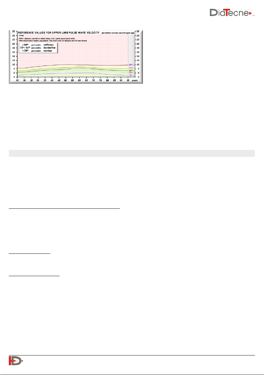
The image was derived from a healthy adult population and refers to the Carotid-Femoral segment with
PWV percentile curves in meters / second
referred to the age: note how PWV increases
with age. This is due to the change of
composition of the arterial walls with a
reduction of the ratio between elastin fibers
and collagen fibers.
!
8
User Manual PulsePen - V. 5.2
Measurement of distances for the Femoral, Tibial,
Dorsalis Pedis Artery: A tape measure is used to
measure the distances between the Carotid Artery
and the Peripheral Artery (Femoral in the
example), between the Carotid Artery and the
suprasternal notch and finally between the
suprasternal notch and the Peripheral Artery.
Measurement of distances for the Brachial, Radial
Artery: with the arm at 45 degrees as in the figure,
a tape measure is used to measure the distances
between the Carotid and the Peripheral Artery
(Radial in the example), between the Carotid and
suprasternal notch and finally between the
suprasternal notch and Peripheral Artery.
Peripheral arteries, on the other side, are
mainly of muscular type, adapting their
lumen according to the sympathetic system.
The image was derived from a healthy adult
population and refers to the Carotid-Radial
segment with PWV percentile curves in
meters / second referred to the age: note
how PWV remains almost constant with age.
In summary, we can say that:
The Carotid-Femoral PWV increases with age
and may be considered an index of biological age of the vascular system. Its increase is also caused by
situations of arterial stiffness due to inflammation, calcification, ...
For this reason, it's considered the gold standard for assessing Arterial stiffness. On the other side, the
Carotid-Radial or the Femoral-Tibial PWV does not significantly change with age and does not provide
information on the biological age of the vascular system. The PWV in this case is mainly related to the
activity of the sympathetic system.
9. Clinical Benefit
Improvement of the primary cardiovascular prevention. The diagnosis of a condition of arteriosclerosis,
even clinically silent, configures a situation of subclinical organ damage, suggesting to the clinician a more
in-depth evaluation of the patient, and possibly inducing changes in the treatment and advice relating to
the patient's lifestyle.
Arterial Stiffness is considered an independent cardiovascular risk factor.
Clinical Condition to Diagnose, Treat / Monitor:
In addition to the diagnosis of arteriosclerosis and aortosclerosis, the examination allows the diagnosis of
isolated holosystolic hypertension in young people and to highlight a condition related to a state of early
vascular aging. The latter condition requires periodic monitoring of the parameters relating to the
condition of vascular stiffness, in order to verify the response to therapy.
Contraindications
There are no contraindications to using the device.
Potential clinical risks
Based on the reports in the literature, also referable to similar devices on the market, no dangerous
situations related to the correct use of the device are detected.
A dangerous condition can be assumed if an attempt is made to perform with the WPP001-ETT the
simultaneous recording of the pressure curves in the two carotids, with simultaneous compression of the
carotid bulbs. The execution of this maneuver configures a known and evident guilty attitude of
unskillfulness on the part of the professional user. There is no indication for the simultaneous recording of
pressure curves in the carotid artery and, even if it is not the correct use of the instrument, this potential
risk condition has been clearly indicated in this manual.
!
9
User Manual PulsePen - V. 5.2

10. Operational Setup
The figure shows an example of an
operating setup: the wRs1 unit is
inserted into a USB socket on the
computer where the PulsePen software
is running and receives data wirelessly
from wEc1 and wTn1.
11. Signal Receiver unit - wRs1
12. ECG unit - wEc1
1. Operating mode signaling LED. This LED blinks green when
the PulsePen software is not running or if the USB driver is
not properly installed. The LED is solid green during
normal operations while it is red during reprogramming /
updating.
1. On / Off button: keep pressed for about 1 sec.
2. Cap for battery replacement: pull away from the unit’s
body. Remove the old battery. Insert the new battery
without ever forcing and respecting the polarity
indicated by the appropriate label. Put the cap back in its
seat by pushing it until clicks.
3. Sockets for the patient ECG cable CV010.
!
10
User Manual PulsePen - V. 5.2

13. Tonometric unit - wTn1
14. Ecg Cable Set: CV010
15. Software
WPulsePen is the software for the capture, display, storage, and analysis of signals with the calculation of
the parameters. It includes the patient database management. It’s possible to make both short-term signal
records (up to 10 ECG/ tonometric complexes) and long-term signal records (up tp 24 hours but in this case
without signal analysis). This software allows for the generation of a patient report, the content of which
must always be verified by a physician expert in the method. DiaTecne s.r.l. takes no responsibility for the
final diagnosis.
To install the software included in the supplied USB drive, proceed by following the instructions given in
the “readme.txt” file: the WPulsePen software will be installed, with its icon on the desktop and the USB
drivers for the wRs1 receiver. Refer to "Usage Problems and Solutions" if you have difficulty.
1. On / Off button: keep pressed for about 1 sec.
2. Cap for battery replacement: pull away from the
tonometer’s body. Remove the old battery pushing it from
the side opposite the opening. Insert the new battery
without ever forcing and respecting the polarity indicated
by the appropriate label. Put the cap back in its seat by
pushing it until clicks.
3. Active part of the tonometric sensor.
Red and black cables.
1. Crocodile for ECG electrodes
2. wEc1 side connector
!
11
User Manual PulsePen - V. 5.2

16. Method of Use
Software Interface
1. New examination.
2. Access to the Patient Archive.
3. Setup and device programming.
4. “On line” instructions (Help / Quick Guide / Tutorial / Manual).
5. Data exchange between computer and wRs1 (green under normal conditions).
6. USB drive wRs1 connection (green if recognized correctly).
7. Graphic indication of the residual battery capacity of wEc1 and wTn1.
8. Remaining battery capacity of wEc1 and wTn1: replace the battery if less than 10%.
9. Icon representing the ECG (QRS) or Tonometric (pressure wave) signal depending on the type of active
sensor.
10. Data coming from wRs1 waiting to be processed: a short bar signals a better situation to a long bar (it
depends on the speed of the computer, other running programs,…).
11. The upper part of the battery symbol turns yellow in standby, i.e. when the “Freeze” is active or in
situations other than that of “real time” acquisition and display of signals.
12. Sensor1 corresponds to the red trace (ECG or Tonometer) while Sensor2 corresponds to the blue trace
(Tonometer only).
Preparation for the exam
B. Start the WPulsePen software.
C. Insert the wRS1 receiver into a USB port and wait for the device to be recognized (fig. 1 - icons 5 and 6
green).
D. Extract the cap of the wEc1 and wTn1 units, insert the
batteries in the appropriate compartment, strictly respecting
the orientation indicated (see Warnings) and put the cap
back in its seat.
E. Let the patient lie down on the medical bed.
If you intend to carry out the examination with two tonometers
at the same time, go directly to the next point "I".
F. Using "fresh" pre-gelled disposable Ag / AgCl ECG electrodes
for crocodile clips, place them in the following way:
•Red: right subclavian region
•Black: left subcostal region
The suggested position can be changed at the operator’s discretion in the presence of ECG signals that are
too small, inverted or altered, for example due to pathologies. Direct contact of the electrodes with
synthetic clothing which could cause disturbance must be avoided, in which case it is advisable to
interpose a sheet of paper.
!
12
User Manual PulsePen - V. 5.2
fig. 1
fig. 2

G. Connect the crocodiles of the patient cable to the respective electrodes according to their type (type A
or type B, see fig. 2)
H. Insert the connectors of the opposite end of the ECG cables into the corresponding sockets of wEc1.
I. Turn on the units you intend to use (wEc1 and wTn1 or two wTn1) holding down the on / off button
until you hear a beep (after about 1 sec). wEc1 produces a single “beep” as well as wTn1 programmed
as Sensor1 (red trace) while wTn1 programmed as Sensor2 (blue trace) produces two “beeps”.
Permitted Sensor Combinations
The correct use of modules wEc1 and wTn1 is based on the assumption that one of the two is set as
Sensor1 and the other as Sensor2: wEc1 is always set as Sensor1 and cannot be changed while wTn1 can
be set in two ways: refer to the Help online of the software for operating instructions.
wEc1 - Sensor1 (1 beep when switched on) + wTn1 set as Sensor2 (2 beeps when switched on). These are
the factory settings for the WPP001-ET system and for the wTn1 unit with the black ring of the WPP001-
ETT system:
✔ +
wTn1 set as Sensor1 (1 beep when switched on) + wTn1 set as Sensor2 (2 beeps when switched on). These
are the factory settings respectively for the wTn1 unit with red and black ring of the WPP001-ETT system:
✔ +
Wrong Sensor combinations
wEc1 - Sensor1 (1 beep when switched on) + wTn1 set as Sensor1 (1 beep when switched on):
✘ +
Both wTn1 modules set as Sensor1 (1 beep when switched on) or as Sensor2 (2 beeps when switched on):
✘ or
!
13
User Manual PulsePen - V. 5.2
+
+

Functionality
New exam:
Carrying out the exam:
Selecting the desired artery a new screen will open where the acquired signals will be displayed once the
wTn1 probe(s) has(have) been positioned on the region to be explored. An automatic signal "Freeze"
function stops the acquisition when no activity is detected on the wTn1-Sensor2 tonometer (blue trace).
The operator must firmly rest his elbow and hold the wTn1 probe as shown in fig. 3 with the fingertips in
contact with the patient's skin, thus minimizing tremors. The probe should be held perpendicular to the
skin and not tilted. It is advisable to consult the Quick Guide contained in the Help-Tutorial. Once a series
of overlapping complexes has been obtained, indicated by the green color of the traffic light at the top of
the screen (see the software Help), the operator can interrupt the acquisition by lifting the wTn1-Sensor2
tonometer. By pressing the icon with the disk symbol or the Enter key, the last heart
complexes recorded, up to a maximum of ten, are automatically saved and
analyzed. At this point, a window will appear for entering the systolic and diastolic
pressure measured immediately before or after, with an external
sphygmomanometer. In the case of a peripheral Artery, the operator will also have
to use a meter to obtain three distances, in millimeters: Carotid - Peripheral Artery,
Carotid - Suprasternal notch and SupraSternal notch - Peripheral Artery.
In the estimation of PWV this allows to apply both methods of distance evaluation
suggested by the international guidelines, i.e. both the “direct method” and the
“subtractive method” - see the relevant paragraph.
At this point a new panel will show the parameters automatically calculated by the
software.
Refer to the online Help for all the additional features available.
Select the icon to start a new exam and
choose a patient from those already in the archive
or enter a new patient's data, such as name,
surname, date of birth, sex: at this point, the keys
corresponding to the various arteries will be
enabled.
!
14
User Manual PulsePen - V. 5.2
fig. 3

Once a series of overlapping complexes have been obtained, indicated by the green light of the traffic light
in the upper central part of the screen, the operator can interrupt the acquisition by lifting Sensor 2.
Exam recording:
Viewing stored exams:
Access the patient database and choose the patient and exam to view. Refer to the “Patient Database”
point.
Determination of the arterial stiffness:
Place the wTn1 probe (or two probes in the case of
the WPP001-ETT model) on the region to be
explored: the acquired signals will be displayed on
the computer screen.
By pressing the icon with the disk symbol or
the Enter key, the last 10 heart complexes acquired
will be automatically saved and analyzed. At this
point, a window will appear for entering the
systolic and diastolic pressure measured with a
sphygmomanometer and for entering the
distances between the landmarks.
Immediately after saving the exam in progress or
by recalling an exam from the patient database,
the calculated parameters are automatically
presented, including PWV (Pulse Wave Velocity)
which represents the arterial stiffness index.
!
15
User Manual PulsePen - V. 5.2
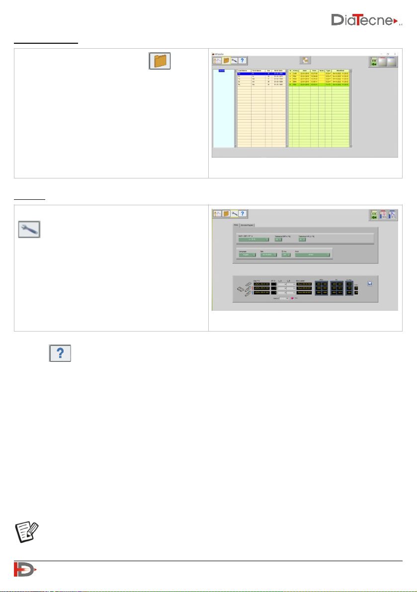
Patient Database:
Settings:
The icon allows you to access the online Help.
Shutdown of device
•To turn off the wEc1 and wTn1 Sensors, press and hold the on / off button until you hear a beep (after
about 1 sec).
•wEc1 and wTn1 turn off automatically when the program is exited or if there is no connection with the
wRs1 unit for more than 30 seconds, for example if the WPulsePen software is not running or the
distance between the units is excessive. The wEc1 e wTn1 Sensors also turn off automatically if they
remain in standby for more than 10 minutes to preserve the battery: in fact, the stay in standby
presupposes no acquisition of signals during this interval and therefore the inactivity of the same
Sensors.
The wEc1 and wTn1 units do not transmit radio frequency until the connection with wRs1 is
established.
Selecting the "Patient Archive" icon lists all
patients with their registered exams, from which
you can choose the one to be displayed on the
screen.
The settings are accessible by clicking on the icon
.
You can choose the language and date format,
program the sensors (radio channel, sensor 1/2,
firmware update), set the tolerance levels, choose
the method of calculating the mean arterial
pressure.
!
16
User Manual PulsePen - V. 5.2

17. Commisioning
The PulsePen device does not require commissioning by personnel authorized and qualified by DiaTecne
s.r.l.
18. Placement
The PulsePen must be kept in a closed environment - enclosed by walls while maintaining the
environmental operating conditions (temperature, humidity, pressure) as reported in the technical
characteristics in this manual. The degree of protection is IP20. The use of explosive gases, flammable
substances or anesthetic gases is not allowed.
The device is intended for use in hospitals, medical clinics or research centers.
19. Maintenance and Cleaning
No particular maintenance operations or periodic calibration of the instrument are necessary for PulsePen.
Cleaning should be done before each use on a new patient and before storing the MD in the case.
wRs1, wEc1: use a soft, clean cloth slightly soaked in alcohol, avoiding infiltration inside.
CV010: use a soft, clean cloth lightly soaked in alcohol for the cables, the “crocodiles” and the connectors
at the ends.
wTn1: use a soft, clean cloth slightly soaked in alcohol for the plastic shell, avoiding infiltration inside. Clean
the metal disc of the sensor with the same cloth, acting gently and without pressing, avoiding infiltration
inside.
20. Usage Problems and Solutions
Check and implement the following suggestions, from top to bottom, until the problem is solved.
The software installation does not complete:
•The installation of the software requires the operator to have the necessary permissions: in a hospital or
research setting it is often necessary to contact the system administrator to proceed.
The wEc1 / wTn1 unit does not turn on (no beeps):
•Check that the battery is the required type, inserted with the correct orientation, and that it is fresh.
•Keep the On / Off button pressed until the acoustic signal is heard (after about 1 sec).
•Remove and reinsert the battery.
There are no signals to the computer:
•fig. 1 - icon 6 red: in this case the USB receiver - wRs1 has not been recognized.
-Close the software, remove and reinsert the wRs1 signal receiver and restart the software.
-If the problem persists, it is recommended that you check with your system administrator that access
to the computer's USB ports is not inhibited. Make sure that the presence of computer protection
software such as Antivirus, Firewall, etc., does not prevent access to external USB devices.
-With wRs1 inserted, launch “DrvInst.exe” in the folder .. \ Program Files (x86) \ WPulsePen or manually
reinstall the USB drivers that are contained in the folder “wRs Usb Driver” if the problem has not been
solved with the previous suggestions.
!
17
User Manual PulsePen - V. 5.2

•fig.1 - icon 6 green and icon 5 red: the wRs1 unit is recognized correctly but the firmware in it installed is
not compatible with the version of the software running on your computer.
-Update firmware and / or software to the latest version. Contact DiaTecne s.r.l. in case of doubts or
problems.
•fig.1 - icons 5 e 6 both green but icons 12 (red and blue) inactive: the wEc1 / wTn1 units do not connect.
-Check that the wEc1 / wTn1 units are turned on (acoustic signal at power on).
-It is necessary that the radio channel of all units wRs1, wEc1, wTn1 is the same and that the relative
firmware are compatible: go to the "settings" panel of the software (fig. 1 - icon 3), select the
programming mode and follow the instructions in the online Help of the software to put the involved
wRs1, wEc1, wTn1 units in programming mode, one at a time, in order to verify and eventually update
what is required. Contact DiaTecne s.r.l. in case of doubts or problems.
•fig.1 - icons 5 e 6 both green and icons 12 (red and blue) active: the system is in “Freeze” mode due to
the absence of tonometric signal on the wTn1 probe - sensor 2 (blue trace).
-Gently touch the tonometric sensor with your fingers.
If it is not possible to solve the problems listed independently or if there are doubts about the operation of
the device, please contact DiaTecne s.r.l. at the following email address: [email protected]. Assistance
will be provided as soon as possible.
21. Mutual interference with other systems
The PulsePen device has been designed to be immune to electrical, electromagnetic, electrostatic and
magnetic disturbances, normally present; similarly, the PulsePen produces a reduced quantity of
disturbances towards the other devices. However, it cannot be excluded that, in particular situations, there
may be operating anomalies also in the form of signal alteration: in this case it is necessary to remove all
potential sources of disturbance when possible or move to a more appropriate location. Considering the
"Intended use" of the device that requires a qualified medical / nurse operator, the latter can easily
recognize an abnormal operating situation, such as the presence of "noise" superimposed to the signal or
alteration of the morphology of the signal and follow the instructions suggested above.
Typical sources of disturbance are “hotspots” / WiFi devices, Bluetooth / Zigbee devices, cell phones and
any type of transmitter in the 2.4 GHz frequency band.
•Electromedical devices require special precautions for electromagnetic disturbances (EMC) and must be
installed in accordance with the information in the following tables.
•Mobile radio frequency communication devices can disturb electromedical devices.
•For the correct functioning of the PulsePen device, the wEc1 and wTn1 units must be within a radius of 3
meters from the wRs1 unit. Greater distances may cause incorrect operation.
•The use of cables and accessories other than those supplied could adversely affect the performance of
the device.
•During use, no other devices should be connected to the patient and should be more than 15 cm away
from the patient, the PulsePen and patient cables.
!
18
User Manual PulsePen - V. 5.2

22. Technical Specifications
General
(*) Accuracy and Precision can be negatively affected by muscle tremors, breath, … and in general "noise" superimposed
on the signal.
wRs1
Capture
16 bit
Sampling Frequency
1000 S/sec
Wireless
ISM @ 2.4 GHz
Electrical protection:
Type EN 60601-1
Degree EN 60601-1
Class II
BF
Degree of protection against penetration of
solids / liquids:
IP20
Electromagnetic Compatibility
EN 60601-1-2 :
Group 1, Class B
Operating Ambient Temperature
from +5°C to +40°C
Transportation and Storage Temperature
from -25°C to +70°C
Relative Humidity
from 30% to 80% non-condensing
Atmospheric Pressure
from 860 to 1060 hPA
Accuracy of PWV estimation
better than ± 0.3 m/s (*)
Precision of PWV estimation
better than ± 1 m/s both intra-operator and inter-operator(*)
PC connection
USB 1.0 / 2.0 - type A
Data transmission
ISM band 2.4 GHz, modulation MSK, ERP = 2 dBm (P ≈ 1.6 mW)
LED
Operating mode signaling
Power supply
< 50 mA @ 5V, powered by the USB connector of the P.C.
Weight
12 g
Dimensions [mm]
67 (L) x 25 (W) x 11 (H)
Material
Bayblend FR3010
!
19
User Manual PulsePen - V. 5.2

wEc1
wTn1
CV010
Batteries:
The technical characteristics that the batteries must meet in order to be used with the wEc1 and wTn1
units are fully specified with the abbreviation “AAA - Alkaline 1.5 V - IEC LR03”.
•“AAA” is the code that identifies the size of the batteries, 10.5 x 44.5 mm nominal.
•“Alkaline” identifies the internal chemical structure. It is a primary battery, i.e. non-rechargeable.
•“1.5 V” indicates the nominal no-load voltage of the fresh battery.
•"IEC LR03" is the IEC coding equivalent to "AAA - Alkaline"
Resolution
0.15 μV
Dynamic range
≥ ± 5 mV
Data transmission
ISM band 2.4 GHz, modulation MSK, ERP = 2 dBm (P ≈ 1.6 mW)
Acoustic Signals
Power on / off
Power supply
Alkaline battery AAA - 1.5V IEC LR03 (indicative autonomy ≥ 50 hours / ≥ 600 exams)
Vibrations
≤ 20 g @ 10 Hz - 2 KHz sinusoidal
Shock
≤ 150 g
Weight
36g senza batteria
Dimensions [mm]
49 (L) x 75 (W) x 21 (H)
Material
Bayblend FR3010
Resolution
0.004 mmHg
Dynamic range
≥ 220 mmHg
Data transmission
ISM band 2.4 GHz, modulation MSK, ERP = 2 dBm (P ≈ 1.6 mW).
Acoustic Signals
Power on / off
Power supply
Alkaline battery AAA - 1.5V IEC LR03 (indicative autonomy ≥ 50 hours / ≥ 600 exams)
Max force to the sensor
4.5 Kg
Vibrations
≤ 20 g @ 10 Hz - 2 KHz sinusoidal
Shock
≤ 150 g
Weight
25 g without battery
Dimensions [mm]
114 (L) x 25 (W) x 20 (H)
Material
Bayblend FR3010
Terminals
Universal for tab, clip ECG electrodes
Connectors
DIN 42802 compliant
Material
TPE + PA
!
20
User Manual PulsePen - V. 5.2
Other manuals for PulsePen
2
This manual suits for next models
2
Table of contents
Other DiaTecne Medical Equipment manuals


Popular Medical Equipment manuals by other brands


Nasco Healthcare
Nasco Healthcare LF00980 instruction manual

EGi
EGi GES 400 MR Series user manual

NRS Healthcare
NRS Healthcare EasyFit Plus+ User instructions

A2J
A2J Pelvi.Loc PL-3DA Series Assembly instruction and manual

Johnson & Johnson
Johnson & Johnson DePuy Synthes SUMMIT SI manual

NordiCare
NordiCare Vira x2 manual


