Dickey-John Control Point User manual

CONTROL POINT®
CONTROL SYSTEM
Operator’s Manual
SINCE 1966
®

OPERATOR’S MANUAL
Control Point®
11001-1489-201702 Rev B
I
Safety Notices ..................................................................................................... 1
Introduction ......................................................................................................... 3
Granular Channel Configuration ....................................................................................... 3
Liquid Channel Configuration ............................................................................................ 4
Spinner Channel Configuration ......................................................................................... 4
Product Application Mechanisms ...................................................................................... 4
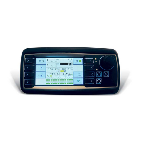
Console ............................................................................................................................................ 5
Switch Module .................................................................................................................................. 6
Keyboard .......................................................................................................................................... 6
Ground Speed Sensor ..................................................................................................................... 6
Feedback Sensors ........................................................................................................................... 6
Valve Control Devices ...................................................................................................................... 7
Hopper Level Sensor (optional) ....................................................................................................... 7
Harnesses ........................................................................................................................................ 7
Technical Support ............................................................................................................. 7
System Installation ............................................................................................. 9
Hardware Kits ...................................................................................................................9
Standard Hardware Kit Console and Switch Module ........................................................................ 9
Optional Hardware Kit for Console only ............................................................................................ 9
Console Placement ......................................................................................................... 10
U-Bracket Mounting ........................................................................................................ 10
Console and Switch Module Installation ......................................................................... 10
Switch Module to Console Connection ........................................................................... 11
Console Mounting ........................................................................................................... 11
Harness Connection ....................................................................................................... 11
Main Harness Connection ............................................................................................... 12
Checking Operation ........................................................................................................ 13
Start-up and Familiarization ............................................................................. 15
Start-up Preparation ........................................................................................................ 15
Start-up Procedure .......................................................................................................... 15
Operate Screen Display Functions ................................................................................. 17
Material/Manual Speed Select ....................................................................................................... 18
Accessing the Current Totals Screen .............................................................................................20
Clearing the Current Totals ............................................................................................. 21
Accessing the Season Totals Screen ............................................................................. 22
Using the Blast Button .................................................................................................... 22
Master Switch in the Unload Position ............................................................................. 23
Keyboard Programming ................................................................................... 25
Logging Configuration Data ............................................................................................ 25
Pre-programming ............................................................................................................ 25
Using the Keyboard and Screens ................................................................................... 26
Miscellaneous Menu (F12) .............................................................................................. 29
Blast Setup ..................................................................................................................................... 29
Time/Date Setup ............................................................................................................................ 30
System Units .................................................................................................................................. 30
Serial Port Configuration ................................................................................................................ 31
Service Menu .................................................................................................................................. 32

OPERATOR’S MANUAL
Control Point®
11001-1489-201702 Rev B
II
Keyboard Programming continued
Sensor Selection ............................................................................................................ 35
Gate Height Sensor ........................................................................................................................ 36
Gate Height Calibration .................................................................................................................. 36
Road Temperature Sensor ............................................................................................................. 37
Temperature Sensor Calibration .................................................................................................... 38
Air Temperature Sensor ................................................................................................................. 39
Air Temperature Sensor Calibration ............................................................................................... 40
12V Boom Switched Output ........................................................................................................... 41
Down Pressure Sensor ................................................................................................................... 42
Down Pressure Sensor Calibration ................................................................................................42
Bed Height Sensor ......................................................................................................................... 43
Bed Height Sensor Connection ...................................................................................................... 43
Bed Height Sensor Calibration ....................................................................................................... 44
Accessing the Operate Mode (F1) .................................................................................. 45
Setting Up Granular Configuration (F3) .......................................................................... 45
Programming Granular Application Rates (F2) .............................................................. 48
Liquid Configuration Setup (F5) ...................................................................................... 50
Setting Liquid Configurations .......................................................................................................... 50
Tank Level Sensor Configuration ................................................................................................... 52
Enabling Tank Level Sensor ........................................................................................................... 53
Tank Empty and Tank Full .............................................................................................................. 53
Tank Alarm ..................................................................................................................................... 53
Tank Capacity ................................................................................................................................. 54
Boom Configuration ........................................................................................................ 55
Programming Liquid Application Rates (F4) ................................................................... 57
Ground Speed Configuration (F7) .................................................................................. 61
Ground Speed Calibration (F7-1) ................................................................................... 63
Spinner Channel Configuration (F8) ............................................................................... 65
Monitor & Reset Accumulators (F9) ............................................................................... 67
Reading System Information (F10) ................................................................................. 69
Performing System Response (F11) .............................................................................. 71
System Calibration ........................................................................................... 73
Recording Calibration Data ............................................................................................ 73
Repeating Calibration Runs ............................................................................................ 73
Maintaining Calibration Accuracy ................................................................................... 73
Calibration System Response (F11) ............................................................................... 75
Granular System Response Calibration ......................................................................................... 75
Fine Tuning System Response Constants ..................................................................... 77
SYS RSPNS Constant .................................................................................................................... 77
Valv Boost ...................................................................................................................................... 78
AFILT .............................................................................................................................................. 78
Proportional Valve Spinner Calibration ........................................................................................... 78
Granular Materials Calibration (F6) ................................................................................ 79
Granular Calibration Fine Tuning ................................................................................... 81
Liquid Materials Calibration (F6) ..................................................................................... 81
Liquid Calibration Fine Tuning ........................................................................................................ 84
Calibrating Spinner Width (F6) ....................................................................................... 84
Troubleshooting ............................................................................................... 87

OPERATOR’S MANUAL
Control Point®
11001-1489-201702 Rev B
III
Appendix A Converting Constants ................................................................. 97
Fine Tuning Application .................................................................................................. 97
Calculating Spreader Constants ..................................................................................... 98
Calibration Data Record Sheet ..........................................................................99
Warranty ............................................................................................................107

OPERATOR’S MANUAL
Control Point®
11001-1489-201702 Rev B
IV

OPERATOR’S MANUAL
Control Point
®
11001-1489-201702 Rev B
SAFETY NOTICES / 1
SAFETY NOTICES
Safety notices are one of the primary ways to call attention to potential
hazards.
This Safety Alert Symbol identifies important safety
messages in this manual. When you see this symbol,
carefully read the message that follows. Be alert to
the possibility of personal injury or death.
Use of the word WARNING indicates a potentially hazardous
situation which, if not avoided, could result in death or serious
injury.
Use of the word CAUTION with the Safety Alert Symbol indicates a
potentially hazardous situation which, if not avoided, may result in
minor or moderate injury.
Use of the word CAUTION without the safety alert symbol
indicates a potentially hazardous situation which, if not avoided,
may result in equipment damage.
DISCLAIMER
DICKEY-john reserves the right to make engineering refinements or
procedural changes that may not be reflected in this manual. Material
included in this manual is for informational purposes and is subject to
change without notice.

OPERATOR’S MANUAL
Control Point
®
11001-1489-201702 Rev B
2 / SAFETY NOTICES

OPERATOR’S MANUAL
Control Point
®
11001-1489-201702 Rev B
INTRODUCTION / 3
INTRODUCTION
The DICKEY-john Control Point®system uses three-channels (three
separate controlled servo loops) on spreader vehicles to simultaneously
control the spreading of granular and liquid ice-control materials. Two
channels control granular and liquid application rates and the third channel
precisely controls spinner speed to maintain even material coverage over
the desired spread width. The dispensing rate varies directly with ground
speed to ensure accurate product application.
Material can also be spread at a preset “BLAST” application rate. This is
normally a very large rate to instantly adjust the target APR (application
rate) coverage for bridges and intersections with a much heavier amount of
material.
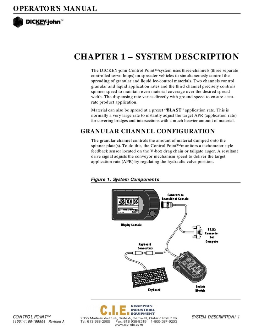
Figure 1 illustrates the Console, Switch Module, and Keyboard.
Figure 1
System Components
GRANULAR CHANNEL CONFIGURATION
The granular channel controls the amount of material dumped onto the
spinner plate(s). The Control Point®monitors a tachometer-style feedback
sensor located on the V-box drag chain or tailgate auger. A resultant drive
signal adjusts the conveyor mechanism speed to deliver the target
application rate (APR) by regulating the hydraulic valve position.
435
SALT
LBS/MILE
LIQUID
GAL/TON
MPH
0% 100%
SPREAD WIDTH
8 MAR 12:25:PM
1234567890-=
QWERTYUIOP[]\
ASDFGHJKL;'
Back
Space
ZXCVBNM
,./
RS232
Connector
for
Computer
Display Console
Keyboard
Connectors
Switch
Module
Keyboard
Connects to
Rear side of Console
OFF AUTOUNLOAD
MASTER
0
0
40
60
80
100
BLAST

OPERATOR’S MANUAL
Control Point
®
11001-1489-201702 Rev B
4 / INTRODUCTION
LIQUID CHANNEL CONFIGURATION
The liquid channel controls the application rate of pre-wetting or de-icing
materials. When pre-wetting, the Control Point® console monitors a
flowmeter-style feedback sensor. Flowmeter feedback can be used when
de-icing. Using feedback data, the pumping mechanism output adjusts the
target application rate by either regulating pump speed or flow blocking.
De-icing systems use up to five boom inputs for applying material to more
than one lane at a time.
SPINNER CHANNEL CONFIGURATION
The spinner channel controls the spinner plate(s) speed with either a
closed-loop (precision) or an open-loop configuration. In the closed-loop
configuration, a tachometer style feedback sensor, mounted on the spinner
assembly, monitors spinner activity. Using the feedback data, the spinner
mechanism speed adjusts for the target setting by controlling the hydraulic
valve position. In open loop systems, the hydraulic valve position is relative
to the width adjust knob setting on the Control Point® Switch Module.
The user must determine the spread-width accuracy needed. Technical
assistance is available through DICKEY-john Technical Support at
PH#1-800-637-2952.
PRODUCT APPLICATION MECHANISMS
The granular and spinner channels use, in addition to feedback (shaft
rotation) sensors, proportional valves to control the product application and
spinner speed. The liquid channel uses, in addition to feedback sensors
(flowmeter), a liquid pump to control product application. The liquid pump
output is controlled by either a 12 volt DC motor, servo valve actuator, or
proportional valve.
Features:
1. Surface-mount console kit for ease of installation.
2. Flexible Switch Module design allows mounting anywhere in the cab
for optimal operator use.
3. Large 160X128 dot-matrix LCD display with backlighting for nighttime
viewing.
4. Single Console button for system power on/off and screen selection.
5. RS-232 port for PC uploading and downloading of data.
6. Detachable keyboard for easy supervisor programming and calibration
using multilevel, menu-driven screens.
7. Custom programming available to minimize setup time.
8. Compatibility with a variety of sensors, servo valve actuators, and
proportional valves available from DICKEY-john or other
manufacturers.
9. Audible and visual alarms for system and operator errors.

OPERATOR’S MANUAL
Control Point
®
11001-1489-201702 Rev B
INTRODUCTION / 5
SYSTEM COMPONENTS
A DICKEY-john Control Point®system consists of six basic components:
1. Console
2. Switch module
3. Ground speed sensor
4. Feedback devices to monitor material application
5. Valve control devices to regulate material application
6. Harnesses to interconnect all system devices
NOTE: The detachable keyboard
(optional) and PC (not
provided) are programming
aids and are not part of a basic
Control Point®system.
Figure 2 shows components in a block diagram. The Console and Switch
Module are to be mounted inside the truck cab either side-by-side or the
Switch Module positioned elsewhere for operator convenience.
Figure 2
System Block Diagram
CONSOLE
The Console displays information on a dot-matrix LCD and uses a single
push-button switch to control system power and to view several operator
screens. Using an external keyboard for programming and placing operator
controls on the Switch Module simplifies the Console.
CONSOLE
• Store User Entered and
Accumulated Data
• Transfer User Entered and
Accumulated Data
• Display APRs (2)
• Display Spread Width
• Display Ground Speed
• Display Time & Date
• Display Current Totals
• Display Season Totals
• Control 3 Channels
KEYBOARD
• Alphanumeric Data Entry
• Program, Calibrate
• Service Access
SWITCH MODULE
• Master OFF/AUTO/UNLOAD
• Channel ON/OFF
• Channel APR INC/DEC
• BLAST Switch
• Spread WIDTH ADJUST Knob
3 Channel
Actuators
Gnd Spd
Sensor
3-Pulsed Feedback
Sensors
3-Analog Feedback
Sensors
RS232 Port

OPERATOR’S MANUAL
Control Point
®
11001-1489-201702 Rev B
6 / INTRODUCTION
An RS-232 port connector, located on the Switch Module harness, permits
data transfer to and from the Console. This port interfaces to a PC for
downloading accumulator and alarm information. Uploading and
downloading configuration information through the port allows data transfer
between consoles (replacing a console or when identical vehicles require
programming/calibration). For multiple units, only one system needs to be
programmed and then the constants can be transferred (downloaded) from
that console, stored in a PC file, and uploaded to the other vehicle's
console. Note: This is only useful on identical vehicles. Transferring
data does not fine-tune each system. It is recommended to run System
Response (F11) if constants are uploaded from another console.
SWITCH MODULE
Standard
The Standard Switch Module harness plugs into the Console and contains
connectors for both keyboard and PC interface as described above. The
operator controls the real-time functions of the Control Point® system from
the seven switches on the Switch Module (refer to Figure 3).
Wireless
The Wireless Switch Module is similar to the Standard, however, it provides
for data transfer to a PC via a wireless transmission to a base station.
KEYBOARD
The keyboard is used to program and calibrate the system. The 86-key,
alphanumeric, PC-compatible keyboard has been environmentally
hardened for use in the ice-control field. After programming and calibration
are finished, the keyboard is usually disconnected and stored.
GROUND SPEED SENSOR
The ground speed sensor generates vehicle speed information for the
console. Sensor electrical pulses proportional to the vehicle ground speed
are vital to system operation because true vehicle ground speed is
necessary for accurate product application. The system can function with a
wide variety of electronic and mechanical speedometer sensors, including
Hall-Effect and Reluctance sensors.
FEEDBACK SENSORS
The feedback sensors send product flow information to the console for
accurate product application. Both granular and spinner channels require
pulsed electrical sensors having an output proportional to the mechanism
speed. The liquid channel accepts either electrical-pulsed sensors or
analog sensors with outputs proportional to material flow (pulsed). A liquid
prewetting system only accepts pulsed feedback while higher capacity
anti-icing systems accept either pulsed or analog.

OPERATOR’S MANUAL
Control Point
®
11001-1489-201702 Rev B
INTRODUCTION / 7
VALVE CONTROL DEVICES
Valve Control devices regulate material flow for accurate control of product
application rates. Normally, granular and spinner channels regulate the
hydraulic oil flow rate to a motor. Liquid channels use several different
configurations.
HOPPER LEVEL SENSOR (OPTIONAL)
The optical light beam of this level sensor is blocked by the granular
material in the spreader bed. When the material level falls beneath the
sensor mounting level, a repetitive beep sounds and an appropriate
message displays in the warning/alarm area of the Operate screen.
HARNESSES
Main Harness Assembly-Connects the Console to the ground speed
sensor, feedback sensors, channel valve (or DC motor) actuators, vehicle
battery, ignition, and additional optional connections (including two-speed
axle, hopper level sensor, and boom sense inputs).
Retro Harness Assembly-Connects a Control Point console to an
ICS2000 harness (refer to Figure 53 in Troubleshooting section).
Other extension harnesses-Other extension harnesses are available that
allow for flexible sensor arrangement. Contact Technical Support for
harnessing alternatives.
TECHNICAL SUPPORT
For technical assistance, call DICKEY-john Technical Support at (217)
438-3371 or Fax (217) 438-6012 or 438-6539. For toll-free calls in either the
USA or Canada, dial 1-800-637-3302.

OPERATOR’S MANUAL
Control Point
®
11001-1489-201702 Rev B
8 / INTRODUCTION

OPERATOR’S MANUAL
Control Point
®
11001-1489-201702 Rev B
SYSTEM INSTALLATION / 9
SYSTEM INSTALLATION
The Console mounts on the vehicle dashboard or other surface suitable for
operator viewing using a U-bracket. The standard (combination) mounting
plate secures the Switch Module immediately to the left of the Console. An
optional mounting plate mounts the Console only.
The Switch Module cable, which plugs into the Console, is long enough to
allow the Switch Module to be placed near the vehicle seat or elsewhere for
operator convenience. If the combination mounting plate is used, the option
remains to later remove the Switch Module from the mounting plate and to
relocate it for convenience.
The system main harness is laid out and connections are made to the
sensor and actuator cables, battery, ignition switch, and additional options
(two-speed axle, hopper level sensor, and boom sense inputs), as required.
Verify all items in the appropriate hardware mounting kit are present:
HARDWARE KITS
STANDARD HARDWARE KIT (46649-0380) FOR CONSOLE
AND SWITCH MODULE:
(1) Combination mounting plate (46649-0580)
(2) U-bracket (46649-0590)
(3) Two 1/4 - 20 x 1 inch hex bolts
(4) Five 1/4 inch split washers
(5) Two rubber washers (46390-0900)
(6) Two knob screws (20072-0022)
(7) Three 1/4 - 20 x 3/4 inch hex bolts
(8) Retaining clip (46649-0350)
(9) Two #6 self-locking hex nuts
(10) Three #6 plastite screws
OPTIONAL HARDWARE KIT (46649-0390) FOR CONSOLE
ONLY:
(1) Console mounting plate (46649-0370)
(2) U-bracket (46649-0590)
(3) Two 1/4 - 20 x 1 inch hex bolts
(4) Five 1/4 inch split washers
(5) Two rubber washers (46390-0900)
(6) Two knob screws (20072-0022)
(7) Three 1/4 - 20 x 3/4 hex bolts
(8) Retaining clip (46649-0350)
(9) Two #6 self-locking hex nuts

OPERATOR’S MANUAL
Control Point
®
11001-1489-201702 Rev B
10 / SYSTEM INSTALLATION
CONSOLE PLACEMENT
The Console mounts inside the cab on any surface permitting easy
readability of the display without obstructing the operator’s view to the road
while driving (See Figure 3). Be sure the opposite side of the mounting
surface chosen has clearance for installing and tightening the mounting
bolts. The combination mounting plate positions the Switch Module to the
left of the Console.
U-BRACKET MOUNTING
1. Place the U-bracket in the exact location for mounting and mark both
drill holes with a pencil or scribe. If the Console is being mounted on
the dash, move and secure wiring and other obstructions located
beneath the dash.
2. Drill two 9/32 inch holes.
3. Position the U-bracket in place on the mounting surface and insert the
two 1 inch bolts.
4. Install the lock washers and nuts and tighten them.
CONSOLE AND SWITCH MODULE INSTALLATION
1. Install the Console onto the mounting plate using three 3/4 inch bolts
and lock washers.
2. When using the combination mounting plate, install the Switch Module
onto the mounting plate using three plastite screws.
3. Two sets of holes exist in the mounting plate to allow for optional
spacing between the Switch Module and Console. If only the Console
mounting plate is used, install the Switch Module at the desired
location. If placed on the vehicle seat, it must be secured in a suitable
manner (possibly using Velcro™ strips) to ensure the control settings
are not accidently changed or activated.

OPERATOR’S MANUAL
Control Point
®
11001-1489-201702 Rev B
SYSTEM INSTALLATION / 11
Figure 3
Console Mounting
SWITCH MODULE TO CONSOLE CONNECTION
1. Plug the circular connector of the Switch Module cable into the rear of
the Console, rotating the connector collar fully-clockwise to lock it.
2. Place the keyboard mating connector (with its pins pointing upward)
between the two studs on the rear of the mounting plate. Capture this
connector with the retaining clip and two self-locking nuts. The 9-pin
RS-232 connector can be secured to the Switch Module cable with a
cable tie, if desired. Figure 1 shows how the Switch Module cable
connects to the Console and keyboard.
CONSOLE MOUNTING
1. Secure the Console and mounting plate (and Switch Module if the
combination mounting plate is being used) to the U-bracket using the
two knob screws. The rubber washers fit between the U-bracket and
the mounting plate tabs.
2. Pivot the Console for the best viewing angle and tighten the two knob
screws.
HARNESS CONNECTION
1. Verify all required “exterior system cables” are installed on the
spreader vehicle according to their separate, individual instructions.
These are defined as the sensor, actuator, ground speed, boom sense,
and hopper level cables.
2. Use dust caps provided on all unused connectors, both internal and
external. This includes keyboard and RS-232 connectors.
U-Bracket
(46649-0590)
Combination
Mounting Plate
(46649-0580)
Optional Console Only
Mounting Plate
(46649-0370)
#6 Self-Locking
Hex Nuts
#6 Self-Locking
Hex Nuts
#6 x 1/2 inch
Plastite Screws
Knob Screw
(20072-0022)
Knob
Screw
(20072-0022)
1/4-20 x 3/4 Inch
Hex Bolts &
Lockwashers
1/4-20 x 3/4 inch
Hex Bolts &
Lockwashers
Retaining Clip
(holds Switch Mod
keybd connector)
(46649-0350)
Note: Mounting hardware for securing
mounting bracket to dash/mounting
panel are not supplied with kit.

OPERATOR’S MANUAL
Control Point
®
11001-1489-201702 Rev B
12 / SYSTEM INSTALLATION
NOTE: Labels have been supplied in
the dust cap kit to be placed on
external extension cables
routed to the flowmeter,
granular and spinner sensors.
Make the Control Point®battery connections last to ensure no
accidental shorts occur during harness handling.
MAIN HARNESS CONNECTION
1. Plug the largest circular connector of the main harness into the
Console, rotating the connector collar fully-clockwise to lock it.
2. Route the harness to a clean, safe area (inside the cab) suitable for
connection to the exterior system cables (from the sensors and
actuators). All connectors on the main harness are identified with
labels to simplify hookup. If a suitable “punch-out” hole in the rear cab
wall or floor is not available to bring in the exterior system cables, cut a
hole approximately two and one-half (21/2) inches in diameter. The
edges of this hole should be covered with a piece of plastic or rubber
U-channel material to protect the insulation of the cables passing
through the hole. Anchor all cables suitable with nylon cable ties to
prevent damage due to flexing and scraping. RTV or silicone caulk can
be used to seal the hole.
Do not connect the RED ignition lead directly to the battery
voltage. This will prevent the system from storing data properly!
3. Connect the RED ignition lead to the “switched” terminal of the ignition
switch. The correct terminal is at 12 volts DC or higher only when the
ignition switch is turned on.
4. If the vehicle has a two-speed axle, connect the terminal of the
YELLOW 2-Speed Axle lead to the appropriate terminal on the
axle-shifter switch.
5. If the vehicle does not have a two-speed axle, insulate the terminal
with electrical tape and tie back this YELLOW lead with a cable tie.
6. Connect the hopper level sensor and boom sense inputs, if used. The
Boom Sense 5 (gray wire) line can be connected to a pre-wet/anti-ice
selector input switch.
Verify battery voltage is 12 volts, NOT 24 volts.
7. Connect both Control Point®main harness battery leads directly to the
vehicle battery. Attach the RED wire to the positive battery terminal
and the BLACK wire to the negative terminal.
IMPORTANT: Use dust caps provided on all unused connectors, both
internal and external. This includes keyboard and
RS-232 connectors.

OPERATOR’S MANUAL
Control Point
®
11001-1489-201702 Rev B
SYSTEM INSTALLATION / 13
CHECKING OPERATION
1. After completing the installation, turn on the ignition switch. The
Console screen should power on displaying the DICKEY-john name,
logo screen, software version, and then the OPERATE screen (refer to
Figure 9).
2. Refer to the Startup and Familiarization section for additional testing.
Figure 4
Switch Module Cabling
435
SALT
LBS/MILE
LIQUID
GAL/TON
MPH
0% 100%
SPREAD WIDTH
8 MAR 12:25:PM
1234567890-=
QWERTYUIOP[]\
ASDFGHJKL;'
Back
Space
ZXCVBNM
,./
RS232
Connector
for
Computer
Display Console
Keyboard
Connectors
Switch
Module
Keyboard
Connects to
Rear side of Console
OFF AUTOUNLOAD
MASTER
0
0
40
60
80
100
BLAST

OPERATOR’S MANUAL
Control Point
®
11001-1489-201702 Rev B
14 / SYSTEM INSTALLATION
Figure 5
System Harness Layout
Gnd Speed
Sensor
Hopper Level
Sensor
+
Battery
Ð
Boom
Sensors
Flowmeter
Tank Level
or
Down Pressure
Granular
Application Rate
Sensor
Spinner
Sensor
Liquid
Valve
Granular
(& Spinner)
2 Speed Axle
Ignition
Alternate sets of connectors
(Insulate and tie back
unused connectors)
CPC connector Main
Harness
12V Relay
Gate Height
Sensor
Road Watch
Adapter

OPERATOR’S MANUAL
Control Point
®
11001-1489-201702 Rev B
START-UP AND FAMILIARIZATION / 15
START-UP AND FAMILIARIZATION
This section defines how the operator (driver) of an ice-control vehicle uses
the controls on the Switch Module and Console to perform standard
operator functions.
NOTE: The detachable keyboard
(optional) is required to
program and calibrate the
system as described in
Keyboard Programming.
Programming during setup allows the operator to view three or four different
screens of data. The Operate screen is the home screen for monitoring
spreader operation and the remaining screens are supportive.
• Material Select/Manual Speed (accessible only when system is
stationary; no ground speed)
• Current Totals
• Season Totals
START-UP PREPARATION
The system must be installed, programmed, and calibrated before
performing the following procedures.
IMPORTANT: Practice the following procedures with the vehicle
stationary to gain familiarity with the operating controls
and screens before applying product.
Figure 6
Switch Module Controls
START-UP PROCEDURE
1. Verify the Switch Module Master Switch is in the OFF position as
shown in Figure 6. If the Master Switch is in the AUTO position during
OFF AUTO UNLOAD
MASTER
0
0
40
60
80
100
BLAST
MASTER Switch
• OFF position - Disables system.
• AUTO position - System operates
relative to ground speed.
• UNLOAD position - Runs system at
maximum speed to unload product.
BLAST Button
• Initiates a rapid pre-programmed
dispersal product rate
Liquid ON/OFF Switches
• Turns liquid channel on or off
Granular ON/OFF Switch
• Turns granular channel on or off
WIDTH ADJUST
Knob
• Adjusts spinner
speed
Liquid INC/DEC (+/–) Switch
• Increments up or down from
pre-programmed application rate.
Granular INC/DEC (+/–) Switch
• Increments up or down from
pre-programmed application rate.
Other manuals for Control Point
1
Table of contents
Other Dickey-John Control System manuals
Popular Control System manuals by other brands
Data Video
Data Video RMC-230 instruction manual
Aqua Control
Aqua Control SL3 Deluxe Wi-Fi manual
Carbide 3D
Carbide 3D SHAPEOKO 3 Assembly guide
Gema
Gema OptiFlex A1 Operating instructions and spare parts list
Foxtech
Foxtech Leo 2 manual

Astral Pool
Astral Pool LumiPlus 75813 Installation and maintenance manual

Securakey
Securakey Radio Key RK-600 Installation & operating guide

TECH FASS
TECH FASS APS mini MDEM 31 user guide
Landi Renzo
Landi Renzo A1 V05 Installation and adjustment manual
Air TEc
Air TEc Expert CYPRES 2 quick guide
HydroQuip
HydroQuip BALBOA BP7 Series Installation & operation manual
Raven
Raven DCS 300 Installation and service manual
