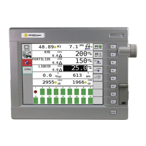
Dickey-John IntelliAg User manual

IntelliAg PDC User Level 1
11001-1510-200904
i
TABLE OF CONTENTS
Introduction .......................................................................................................... 1
Features............................................................................................................................. 1
Main Work Screen ............................................................................................................. 1
Work Screen Symbols ....................................................................................................... 2
Target Rate ....................................................................................................................................... 2
Target Increase/Decrease % Rate.................................................................................................... 2
Target Preset Rate............................................................................................................................ 2
Implement Lift Switch ........................................................................................................................ 2
Task Controller.................................................................................................................................. 3
Row Indicators .................................................................................................................................. 3
Autopilot Steering Navigation............................................................................................................ 3
Accumulators .................................................................................................................................... 3
Population Row Scan........................................................................................................................ 3
Singulation Average Population ........................................................................................................ 4
Material Name................................................................................................................................... 4
Population Max Row ......................................................................................................................... 4
Population Min Row .......................................................................................................................... 4
Pre-Operating Preparation .................................................................................. 5
Pre-Defined Constants ...................................................................................................... 5
Fill Disk.............................................................................................................................................. 5
System Operation ................................................................................................ 7
Start ................................................................................................................................... 7
Stop ................................................................................................................................... 7
Operate Function Buttons .................................................................................................. 8
Master Switch On/Off ........................................................................................................................ 8
Next Channel .................................................................................................................................... 8
Increment .......................................................................................................................................... 8
Decrement......................................................................................................................................... 8
Inc/Dec Reset to Target .................................................................................................................... 8
Turn On/Off Channel......................................................................................................................... 8
Next Screen ...................................................................................................................................... 9
Non Operate Mode Buttons ............................................................................................... 9
Next Page ......................................................................................................................................... 9
Planter Fill Disk ................................................................................................................................. 9
Diagnostics........................................................................................................................................ 9
Alarm Log.......................................................................................................................................... 9
Summary........................................................................................................................................... 9
Additional Operating Functions........................................................................................ 10
Precharge Time............................................................................................................................... 10
Delay Time ...................................................................................................................................... 11
Flush Enable ................................................................................................................................... 11

IntelliAg PDC User Level 1
11001-1510-200904
ii
TABLE OF CONTENTS
Sys Infor and Diagnostics ................................................................................ 13
Diagnostics ...................................................................................................................... 13
CH Setpoint ..................................................................................................................................... 13
CH Target ........................................................................................................................................ 13
CH Actual Rate................................................................................................................................ 13
CH RPM/GPM ................................................................................................................................. 14
CH PWM.......................................................................................................................................... 14
CH Pulse Count............................................................................................................................... 14
CH Freq Filt ..................................................................................................................................... 14
Freq REL GSPD .............................................................................................................................. 14
Freq Dig GSPD................................................................................................................................ 14
Freq Press 1 .................................................................................................................................... 14
IO Hopper 1 ..................................................................................................................................... 14
IO Imp Lift ........................................................................................................................................ 15
APP ID............................................................................................................................................. 15
Sol PWR Volt................................................................................................................................... 15
ECU PWR Volt ................................................................................................................................ 15
Snsr PWR Volt................................................................................................................................. 15
Gnd Volt........................................................................................................................................... 15
Diagnostics Manual Valve Position ................................................................................. 15
Manual Open of Channel................................................................................................................. 15
Information Screen .......................................................................................................... 16
Acknowledging Alarm Conditions .................................................................................... 17
Alarm Log ........................................................................................................................ 17
Alarm Detail ..................................................................................................................... 18
Troubleshooting & Alarms ............................................................................... 19
Warranty.............................................................................................................. 21

OPERATOR’S MANUAL
IntelliAg PDC User Level 1
11001-1510-200904
INTRODUCTION / 1
INTRODUCTION
The IntelliAg application controller is a precision farming system that
provides communication between the implement and tractor. Because
IntelliAg is designed to the ISO 11783 standard, it is interchangeable with
other manufactuers’ compatible equipment.
The DICKEY-john IntelliAg system can be used with:
• Sprayers
• Fertilizer spreaders
• Anhydrous bars
• Planters
• Air seeders (strip till/seeding)
FEATURES
• Controls hydraulic valves (pulse-width modulated and servo)
• Variable rate application
• Logs “as applied” data
• Monitors up to 196 rows of seeding
• Monitors inputs such as hopper level, air pressure, and shaft speed
• Retains information in the event of a power failure
• Full screen alarms identify abnormal or failed operation on all enabled
system component/controls
MAIN WORK SCREEN
The Main Work screen is divided into 4 areas (Figure 1):
1. Enabled system applications
2. Main Work Screen area that displays application control status
3. IntelliAg buttons that perform IntelliAg functions
4. Row Indicators that monitor seed rate
The IntelliAg application control is turned on and off using an installed
“optional” Master Switch or an assigned Master Switch On/Off button on the
VT.
The Virtual Terminal (VT) is in Operate mode when the Master Switch is in
the ON position and the implement is down. In this mode, all enabled
system components and control channels are operational, as well as all row
monitoring functions and system accumulators.
When the Master Switch is in the OFF position and/or the implement is
raised, all control and monitoring functions cease.

OPERATOR’S MANUAL
IntelliAg PDC User Level 1
11001-1510-200904
2 / INTRODUCTION
Figure 1
Work Screen
WORK SCREEN SYMBOLS
TARGET RATE
The Target Application Rate displays when Master Switch is off. The actual
applied rate appears bold and in larger font during Operate mode.
TARGET INCREASE/DECREASE % RATE
The Increase/Decrease rate is the percentage change being applied each
time the Material Increase/Decrease button is pressed during Operate
mode.
TARGET PRESET RATE
The Target Preset Rate is the applied rate that was entered at the Material
Configuration Setup screen and increases or decreases when the Material
Increase/Decrease button is pressed during Operate mode.
IMPLEMENT LIFT SWITCH
When an implement lift switch is installed, the Main Work screen will identify
if the implement is in the up or down position. Using an implement lift switch
automatically turns the control channels on and off without turning the
master switch off. The Implement Lift Indicator must be in the Down position
for the control channels to operate. The Implement Lift Switch box on the
Ground Speed Configuration screen must be enabled if an implement
lift switch is used.
Refer to the Implement Lift Sensor instructions for installation location.
123
4
+
RATE 1
Implement Lift
Indicator
(Down Position-GREEN)
Implement Lift
Indicator
(Up Position-RED)

OPERATOR’S MANUAL
IntelliAg PDC User Level 1
11001-1510-200904
INTRODUCTION / 3
TASK CONTROLLER
The Task Controller icon appears on the Main Work screen when Task
Controller is active and controlling the application rate. Return to Task
Controller to stop a task.
ROW INDICATORS
Row Indicators in the bar graph area on the bottom of the Work screen
indicate seed flow rate for each row.
The following symbols illuminate in the bar graph area.
Figure 2
Row Indicator Symbols
AUTOPILOT STEERING NAVIGATION
Autopilot Steering Navigation can be engaged and disengaged from the
Main Work screen and displays AB line position, cross-track error, % swath
complete, and End of Row Alarm status.
ACCUMULATORS
Some data item values can be reset to zero from the Main Work screen. An
accumulator displays (e.g., Area 1 Field, Seed Count, etc.) on the active
screen and can be reset to zero by placing a checkmark in the box next to
the data item. Only accumulators on the currently-displayed screen can be
reset. Accumulators are reset independently and can only be reset when
the master switch is OFF. Once an accumulator has reached its maximum
value, it will roll over to 0.0.
POPULATION ROW SCAN
Pop Row Scan displays all active seed rows population in seeds per acre
(or seeds/Ha) for each detected seed sensor. The value to the left side
displays the current row number being scanned. The value on the right is
the population data. The scans continue sequentially in four-second
intervals unless the rotary knob is used to select a particular row number for
continuous view. This Data Item displays on an entire row of the work
screen.
T C T C
Setting Task
Controller Rate
Logging Data
to SD card
T C
Setting Task
and Logging
Data
1
Row assignment
to channel
Planting at
desired rate
High Population
Low Population
Row Failure
XRow off
manually
or pattern
Blockage
Not planting
Master Switch off
!Row off by control
and seeds detected Off Row
Off
Press to
engage and
disengage
3
0.00
ACT
Reset box
0.0
5
KS
AC

OPERATOR’S MANUAL
IntelliAg PDC User Level 1
11001-1510-200904
4 / INTRODUCTION
SINGULATION AVERAGE POPULATION
Singulation Average displays the average percent seed singulation of the
rows that are configured for population. Singulation refers to the portion of
seeds planted individually, rather than in groups.
MATERIAL NAME
Active Material Name for a control channel being applied created at the
Control Channel screen.
POPULATION MAX ROW
Pop Max Row displays the seeding row with the maximum population in
seeds per acre (or seeds/Ha). The value to the left side displays the current
row number. The value on the right is the population data. This Data Item
displays on an entire row of the work screen.
POPULATION MIN ROW
Pop Min Row displays the seeding row with the minimum population in
seeds per acre (or seeds/Ha). The value to the left side displays the current
row number. The value on the right is the population data. This Data Item
displays on an entire row of the work screen.
0 %
MATRL 1
0.0
AC
KS
1AC
KS
0.0
4AC
KS
AC
KS

OPERATOR’S MANUAL
IntelliAg PDC User Level 1
11001-1510-200904
PRE-OPERATING PREPARATION / 5
PRE-OPERATING PREPARATION
PRE-DEFINED CONSTANTS
The IntelliAg system is loaded with pre-defined constants. Any constants
that require modification must be changed by an authorized user, such as
the dealer or distributor the system was purchased.
FILL DISK
Planters should perform a fill disk for all control channels at every system
startup or a variety/seed-type change. This ensures no voids are left in the
field when starting to plant.
1. From the Main Work screen, press the Fill Disk button.
2. Raise the implement.
3. With brakes locked and transmission in the park position, start the
engine.
4. Engage hydraulics and run engine at normal speed until hydraulic fluid
is at operating temperature.
Implement will begin to operate after pressing the Start button.
Ensure that all persons and objects are away from the implement
to avoid personal injury.
5. Press the Start button. The seed meters will turn for 1 revolution, then
stop.
6. Pressing the Stop button will also terminate the test.
Figure 3
Fill Disk Screen for All Planter Controls

OPERATOR’S MANUAL
IntelliAg PDC User Level 1
11001-1510-200904
6 / PRE-OPERATING PREPARATION

OPERATOR’S MANUAL
IntelliAg PDC User Level 1
11001-1510-200904
SYSTEM OPERATION / 7
SYSTEM OPERATION
START
1. Lower the implement to operating position engaging the implement
switch, if enabled.
2. With the hydraulic system engaged and the tractor at its normal
operating RPM, set the master switch to the On position. All enabled
control channels will begin controlling at the current ground speed. All
accumulators will begin recording data.
When the implement is down and the master switch is in the On
position, the machine is fully operational. All necessary
precautions must be taken to ensure user safety. Failure to
practice all necessary caution may result in serious injury or
death.
STOP
1. Set the master switch to the Off position. All control channels will
cease operation and all data accumulation will halt.
2. Operation will immediately stop when ground speed is 0.
3. Raise implement to disengage implement lift, if enabled.
Figure 4
Main Work Screen Functions
300
Target Rate
Inc/Dec %
Target Rate
Preset Enabled
Accumulator
Reset
Implement Lift
Up/Down
Indicator
Row
Indicators

OPERATOR’S MANUAL
IntelliAg PDC User Level 1
11001-1510-200904
8 / SYSTEM OPERATION
OPERATE FUNCTION BUTTONS
Virtual buttons on the display are used to interact with the IntelliAg system.
MASTER SWITCH ON/OFF
The Master Switch On/Off button is available only when the button is
configured to display on the Virtual Terminal in those applications that have
no master switch installed in the cab.
NEXT CHANNEL
The Next Channel button selects the next available channel for changes of
rate or to turn channel off. A channel can also be selected by touching the
channel on the screen. The active channel can be set to ON or OFF by
selecting the On/Off Channel button described below. The active channel is
displayed in reverse video display in a multiple channel configuration. The
Target Rate for a channel can be adjusted by using the Inc/Dec buttons
described below. The channel’s Inc/Dec buttons, as well as the ON/OFF
buttons, display the current channel label. This key is visible only when
multiple channels have been configured.
INCREMENT
The Increment button increases the active channel’s target rate by the
amount specified in the Inc/Dec % or rate table setup for that material.
Increment can be pressed several times to increase the target rate by the
specified amount for every actuation until the maximum rate value or preset
value is reached. The active channel/material is displayed in the button text.
DECREMENT
The Decrement button decreases the active channel’s target rate by the
amount specified in the Inc/Dec % or rate table setup for that material.
Decrement can be pressed several times to reduce the target rate by the
specified amount for every actuation until the minimum rate value or preset
value is reached. The active channel/material is displayed in the button text.
INC/DEC RESET TO TARGET
The Inc/Dec Reset to Target button is used to return the active channel to
the original material target rate. This button is only available for channels
that are active and have had the target rate adjusted using the Increment or
Decrement buttons in Inc/Dec% mode. The active channel displays in the
button text.
TURN ON/OFF CHANNEL
The Turn On/Off Channel buttons turn the active channel ON and OFF,
respectively. Channels that are set to OFF will not operate when the master
switch is set to the ON position. Turning a channel OFF is not the same as
disabling a channel in Channel Setup mode. The active channel is
displayed in the button text. If the key text is OFF, this is the action that will
be performed when the key is pressed.

OPERATOR’S MANUAL
IntelliAg PDC User Level 1
11001-1510-200904
SYSTEM OPERATION / 9
NEXT SCREEN
The Next Screen button displays information on the next configured work
screen. The number to the left of the graphic identifies the current screen.
The number on the right identifies the next screen to display. The Next
Screen button only displays if multiple screens are configured.
NON OPERATE MODE BUTTONS
The following buttons appear when the Master Switch is OFF and are
available when the system is not operating.
NEXT PAGE
The Next Page button displays additional buttons used to interact with the
IntelliAg system in a nonoperating mode.
PLANTER FILL DISK
The Planter Fill Disk button fills the seed meters with seed to allow instant
seed flow when the control is turned on. The seed meters will rotate on ALL
ACTIVE planter control channels one revolution and then stop. Performing
a fill disk is recommended at every system startup or a variety/seed-type
change.
DIAGNOSTICS
The Diagnostics button accesses the Diagnostics screen. Various system
operating parameters are displayed on this screen. There is no
user-entered data on this screen.
ALARM LOG
The Alarm Log button accesses the Alarm log screen. An account of the
previous alarms issued is stored here. There is no user-entered data on this
screen. Not all alarms are recorded in the alarm log.
SUMMARY
The Summary button accesses the Summary screen and provides an
overview of system configurations for enabled channels. Specific setup
screens can be accessed (User Level 2 and 3 only) by pressing inside the
yellow boxes for Channel, Material, Row, Module, Speed Set, and
Accessory Sensor screens.

OPERATOR’S MANUAL
IntelliAg PDC User Level 1
11001-1510-200904
10 / SYSTEM OPERATION
ADDITIONAL OPERATING FUNCTIONS
Precharge Time, Delay Time, and Flush Enable are features that only
function if configured in Setup mode and setup under user Level 2.
PRECHARGE TIME
Precharge Time is typically used in applications that have significant
distance between the storage bulk tank and the implement row unit where
seed placement takes several seconds due to the travel time of the seed/
fertilizer from the bulk tank to the ground. When the precharge feature is
activated, material will dispense at the rate at which the precharge ground
speed is set.
The precharge feature will operate until the precharge time lapses or the
precharge ground speed has been exceeded. If ground speed stops while
in precharge mode, the feature will abort.
A precharge alarm will display any time the preset feature is established or
changed and the master switch is turned on.
The precharge feature is applicable to planter control, granular seeding,
fertilizer, and liquid control channels.
NOTE: Master switch must be turned
ON to activate a precharge
state.
Operating the Precharge function:
1. Turn the master switch on.
2. The precharge feature will automatically initiate when the master
switch is turned on and the ground speed is less than the precharge
ground speed, but greater than 0.
The rate instrument will populate with the word “CHARGE” and the
countdown timer. The timer indicates how much precharge time is left
before precharge will abort.
Figure 5
Precharge Time and Delay Time
300
CHARGE
9
CHARGE 9
Precharge Time
Activated
300
CHARG
DELAY 9
Delay Time
Activated

OPERATOR’S MANUAL
IntelliAg PDC User Level 1
11001-1510-200904
SYSTEM OPERATION / 11
DELAY TIME
NOTE: Delay Time functionality may
work differently than described
if the system has been
purchased direct from the
original equipment
manufacturer. Refer to the
manufacturer’s operator
manual for further instruction.
Delay Time determines the length of time before a control channel will start
after the master switch has been turned ON and the implement switch is in
a lowered position.
• The system will immediately shutdown the channel when the ground
speed is less than the shutoff speed.
• The system will delay the channel shutdown if the master switch is
turned OFF and the ground speed is greater than the shutoff speed.
The rate instrument will populate with the word “DELAY” and the countdown
timer appears on the screen indicating when the channel will turn ON
(Figure 5).
FLUSH ENABLE
NOTE: Flush Enable will abort if the
button is pressed during a
Precharge state.
The Flush Enable feature is typically used to begin dispensing material at a
higher rate when the tractor is below shutoff speed, i.e. during startup or
turn around conditions. Material will dispense at the rate set at the ground
speed setup screen.
Flush enable is applicable to granular seeding, fertilizer, or liquid control
channels.
Figure 6
Flush Enable (Main Work Screen)
NOTE: Prechard, Delay Time, and
Flush Enable are features that
only function if configured in
Setup mode and setup under
User Level 2.
Operating the Flush Enable function:
1. Ensure the master switch is turned ON and ground speed is below
shutoff speed.
2. Press and hold the Flush Enable button to dispense material.
3. Release the Flush Enable button to stop dispensing material. Once
speed is above shutoff speed, flush is aborted and ground speed
based control will take over.
FLUSH
300
FLUSH Press and hold
Flush to activate
FLUSH

OPERATOR’S MANUAL
IntelliAg PDC User Level 1
11001-1510-200904
12 / SYSTEM OPERATION

OPERATOR’S MANUAL
IntelliAg PDC User Level 1
11001-1510-200904
SYS INFOR AND DIAGNOSTICS / 13
SYS INFOR AND DIAGNOSTICS
In order to view the following information and diagnostics screens, the
master switch must be set to the OFF position.
DIAGNOSTICS
The Diagnostics screen provides various information from feedback
sensors, valve output, and system voltages of the WSMT module. The
control valve can be manually opened on this screen when necessary.
Each channel has its own Diagnostics screen. None of the items on the
screen can be edited. However the Channel Pulse Count data can be reset.
The system may be active while the Diagnostic screen is displayed.
Press the Diagnostics button to access the Diagnostics screen.
Figure 7
Diagnostics Screen
CH SETPOINT
The Channel Setpoint value is calculated by the system. It displays the
expected feedback frequency of the application rate sensor or flowmeter
used for that channel’s feedback.
CH TARGET
The Channel Target value is the current channel’s rate as entered into the
Target Rate constant on the Channel Configuration screen.
CH ACTUAL RATE
The Channel Actual Rate value is the current channel’s actual controlled
rate with the system active.

OPERATOR’S MANUAL
IntelliAg PDC User Level 1
11001-1510-200904
14 / SYS INFOR AND DIAGNOSTICS
CH RPM/GPM
The Channel RPM/GPM value is the current RPM/GPM. The sensor
constant and gear ratio parameters entered on the Channel Configuration
screen allow the RPM/GPM to be calculated.
CH PWM
The Channel PWM value is the current pulse width modulation (PWM)
output drive signal to the solenoid valve. The higher the number, the further
the valve opens.
CH PULSE COUNT
The Channel Pulse Count value is the accumulated pulse count detected
from the channel feedback sensor. This value may be reset by pressing the
Reset Channel Pulse Count button.
CH FREQ FILT
The Channel Frequency’s Filtered value is the filtered frequency output
from the channel feedback sensor.
FREQ REL GSPD
The Frequency Reluctance Ground Speed value is the reluctance sensor
output signal in hertz (hz). This value is present when ground speed is
provided by a reluctance sensor connected to the actuator harness.
FREQ DIG GSPD
NOTE: In some instances, FREQ REL
GSPD and FREQ DIG GSPD
read the same values
simultaneously depending upon
the sensor used. This is normal
and does not impact operation.
The Frequency Digital Ground Speed value is the digital sensor output
signal in hertz (hz). This value is present when ground speed is provided by
a radar sensor or other digital speed sensor connected to the actuator
harness.
FREQ PRESS 1
The Frequency Pressure value is the output frequency signal of the air
pressure sensor in hertz (hz). This value will typically fall between 200 hz
and 1100 hz.
IO HOPPER 1
The IO Hopper 1 value is the current state of the hopper sensor. If the
sensor is not blocked, the value will be “1”. A blocked sensor’s value will be
“0”.

OPERATOR’S MANUAL
IntelliAg PDC User Level 1
11001-1510-200904
SYS INFOR AND DIAGNOSTICS / 15
IO IMP LIFT
NOTE: If the values are reversed and
the value displays a “1” when
the implement is raised, the
wiring for the implement switch
will need to be reversed so that
an accurate readout is
achieved.
The IO Implement Lift value displays the current state of the implement
status switch. This value will be “1” when the implement is down. The value
will be “0” when the implement is raised.
APP ID
Hardware identification only. Not applicable to the end user.
SOL PWR VOLT
The Solenoid Power Voltage value displays the detected solenoid power
voltage. This voltage level is the high current voltage leg of the system
which is used to power high current solenoids and valve actuators. This
value will generally be equal or nearly equal to the tractor battery voltage.
ECU PWR VOLT
The Electrical Control Unit (ECU) Power Voltage value is the detected ECU
voltage. This voltage level is the low current voltage leg of the system and is
used to power modules and sensors. This value will generally be equal or
nearly equal to the tractor battery voltage.
SNSR PWR VOLT
The Sensor Power Voltage value is the detected output voltage to the seed
sensor on the Working Set Master (WSMT) module. This value is typically
+8 VDC.
GND VOLT
If the system is properly grounded, this value is typically 2.50V on software
versions older than 2.7. Software versions newer than 2.7 and WSMT
software is 0V.
DIAGNOSTICS MANUAL VALVE POSITION
Manual opening of a selected channel’s valve is used for calibration or
troubleshooting purposes in the case of system failure.
Press the Diagnostics button to access the Diagnostics screen.
1. The Diagnostics screen will show Channel 1 as a default.
– If a channel other than Channel 1 needs to be selected, press the
Next Channel button until the appropriate channel displays. The
Next Channel button only displays when more than one channel is
configured.
MANUAL OPEN OF CHANNEL
1. Press the Enable Manual Valve button to run the current selected
channel. This allows for manual open and close of valve position.
IMPORTANT: The Enable feature will only operate on the Diagnostics
screen.

OPERATOR’S MANUAL
IntelliAg PDC User Level 1
11001-1510-200904
16 / SYS INFOR AND DIAGNOSTICS
2. If the Disable Manual Valve button is displayed, the selected channel
has already been enabled for manual valve position operation.
3. Set the Master Switch to the ON position.
4. Press the Increment button to open the channel’s valve. The Channel
Pulse Width Modulation (PWM) data item displays the current PWM
signal that is being output to the valve.
5. The Increment button must be pressed repeatedly to increase the
PWM signal to the valve. Each press will increase the signal by 2 hertz
(hz). The Channel Pulse Count and Channel Frequency Filter values
will display the current output of the feedback sensor.
6. Press the Decrement button to decrease the PWM signal and close
the valve. The Decrement button must be pressed repeatedly to
decrease the PWM signal to the valve. Each press will decrease the
signal by 2 hertz (hz).
7. The active channel is displayed in the button text.
8. Turn the master switch off to shutdown control channel.
INFORMATION SCREEN
The Information screen displays the module software versions connected to
the system and is typically used for troubleshooting. No information on the
screen can be edited.
Each module connected is identified by module type, module position, and
serial number. Module position cannot be altered on this screen and can
only be established on the Module Configuration screen.
Press the Information button to access the Information screen.
NOTE: The Password button on the
Information screen provides
access to the Password screen
to reset User Levels.
Passwords are available to
Great Plains’ authorized users.
Figure 8
Information Screen

OPERATOR’S MANUAL
IntelliAg PDC User Level 1
11001-1510-200904
SYS INFOR AND DIAGNOSTICS / 17
ACKNOWLEDGING ALARM CONDITIONS
Various alarm conditions may be presented whenever the system
encounters an abnormal condition or detects a specific alarm. Alarms are
typically in a full screen display describing the alarm and, dependent upon
the alarm type, may give instructions on how to fix the alarm. Each alarm
type has an associated alarm number which can be cross-referenced in the
Troubleshooting and Alarms section.
Some alarms (such as the Master Switch alarm) require a specific action
before the alarm condition will cease. In these cases, instructions are
indicated on the alarm display.
Other alarms can be acknowledged by pressing the Alarm Cancel button
of ESC key.
Alarm details can only be cleared by a Level 2 or Level 3 User.
ALARM LOG
The Alarm Log screen provides a list of specific alarms that have been
issued during system operation. Information displayed on the Alarm Log
screen is informational only and cannot be edited.
Each time specific alarm conditions are detected it is logged and
communicated to the WSMT.
To View Alarm Log:
1. Press the Alarm Log button to access the Alarm Log screen.
– The number of the alarm, along with the alarm description displays.
– Up to 20 alarms can be recalled.
– Each alarm occurrence can have up to 5 instances of the alarm
tagged with a date and time stamp.
2. To select specific alarm details, press the Previous or Next buttons to
move the small display arrow next to the desired alarm number.
3. Press the Alarm Detail button to view all of the occurrences of the
selected alarm.
– The down arrow in the lower left at screen bottom signifies that
more alarms are present and accessible by pressing the Previous
or Next buttons.

OPERATOR’S MANUAL
IntelliAg PDC User Level 1
11001-1510-200904
18 / SYS INFOR AND DIAGNOSTICS
Figure 9
Alarm Log Screen
ALARM DETAIL
1. To view specific alarm details, press the Alarm Detail button.
– The time and date of the selected alarm displays for each occurred
instance.
– The Alarm Log will save up to 5 instances of the selected alarm.
Figure 10
Alarm Detail Screen
Other manuals for IntelliAg
1
Table of contents
Other Dickey-John Control System manuals
Popular Control System manuals by other brands
Bosch
Bosch Rexroth IndraMotion MTX 11 VRS Applications manual
Siemens
Siemens SIMATIC PCS 7 BOX manual
Thermon
Thermon TraceNet TCM18 Installation, Start-Up, and Maintenance Guide
LD
LD LDDSP44K user manual
Wachs
Wachs Vitals Reference manual
OPW
OPW Petro Vend 200 M1010 Installation, operation and maintenance guide
Sulzer
Sulzer ABS PC 242 user guide
potenza
potenza Aura 8 user guide

Penn
Penn P78 Series installation guide

ADVANTAGE AIR
ADVANTAGE AIR MyApp2 installation instructions
Certified Cirus Control Systems
Certified Cirus Control Systems Single Channel Motor Control Operation manual
Danfoss
Danfoss ADAP-KOOL AK-SM 800 Service guide

