Dickson TH8P3 User manual

Default Recorder Settings
This manual applies to: TH8P0, TH8P2, TH8P3 and TH8P5
7 day chart rotation
32°F - 120°F (TH8P0, TH8P2)
-20°F - 120°F (TH8P3, TH8P5)
Quick Start
1. Remove the protective pen caps.
2. Check to make sure the Replaceable Sensor is connected firmly to the recorder. If using model TH8P3/5 make sure the
extension cord is connected firmly to the recorder and that the Replaceable Sensor is plugged in firmly to the extension
cable.
3. Insert batteries and plug in AC adapter (See Button Operations below).
• TH8P0: four (4) AA batteries required;
• TH8P2/3/5: four (4) AA batteries backup power only (See Power section for backup life). Unit will power on.
4. The instrument will move pens to the appropriate readings.
5. The blue pen has a longer pen arm and records humidity or dew point (depending on your dip switch selection. The red
pen has a shorter arm and records temperature. The pens are offset to allow the red pen to glide under the blue pen.
The blue pen indicates the correct time and the red pen precedes it by 3/16 of an inch.
6. Install the chart that matches the Dip Switch settings (See Dip Switch Setup below).
7. Press the PEN HOME key to move the pens to the outside of the chart. The pen is automatically raised off the chart.
8. Remove the old chart, place the new chart on the Chart Hub being certain that the edge of the chart slides under the
Chart Guide Clips located at the outside of the chart.
9. Set the appropriate time. There are two ways to adjust the chart and set the appropriate time:
Phone: 1-800-757-3747 or 1-630-543-3747 | Fax: 1-630-543-0498 | Email: support@dicksondata.com | Website:DicksonDate.com
TH8
8” (203mm) Temperature & Humidity Chart
Recorder
Option 1:
Set the chart time manually by inserting a coin into the groove in the chart hub and turning clockwise until the correct
hour (and day if applicable) on the chart is referenced to the timing arrow (just to the right of the pen tip on the dial).
Press Pen Home to move the pens back onto the chart.
Option 2:
The following feature should be used for fine adjustments only.
To adjust the chart time, press and hold Adjust-Up and Adjust-Down buttons located on the back of the unit next to
the dip switch (See Button Operations below).
The green LED will blink rapidly for about five seconds, and then the LED will remain solid green. While in this state
the Adjust-Up button will move the chart backward (counter clockwise) and the Adjust-Down button will move the
chart forward (clockwise).
Rotate the chart until the correct hour (and day if applicable) on the chart is referenced to the timing arrow. Once you
have set your chart, press the Pen Home button to exit Chart Adjust Mode. The unit will take one minute to exit the
Chart Adjust Mode once Pen Home is pressed. Press Pen Home to move the pens back onto the chart.
Place the TH8 recorder on a flat vibration-free surface. Be sure it is in a vertical position and level. For best performance and
longevity, the location should be a clean environment, free from dust and corrosive fumes. Do not exceed temperature
specifications. Wall Mount: Keyhole slots are provided on the TH8recorder for wall mounting.
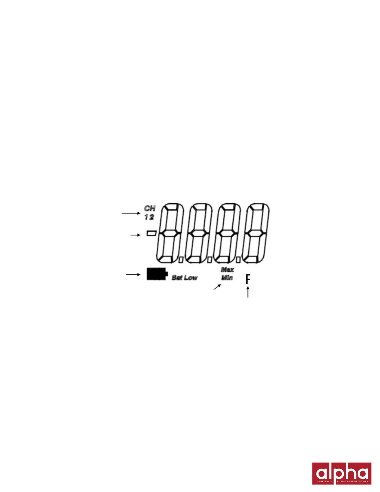
Display Symbols
On/Off
The On/Off key turns the unit on and off.
Pen Home (Down Arrow)
If the pens are located on the outside edge of the chart, press the Pen Home to move pen(s) to recording position. If the pens
are located on the chart, press the Pen Home key to move the pen(s) to the outside edge of the chart.
Alarm Optional
Pen 1 = Red Pen
Pen 2 = Blue Pen
1. To set the alarm, make sure unit is on and press and hold the Alarm button. The LED will blink red rapidly for about 5 s,
then the LED will turn solid green. Release the Alarm button and the LED will turn solid red. At this point the display will
show “On” or “Off”.
Pressing either the Adjust-Up or Adjust-Down buttons, located on the back of the unit next to the dip switch, will toggle
the alarm on or off.
Channel indicator
Current Reading or
Flashing “ALRN”
when in alarm
Low Battery Indicator
Unit of measure for
channel displayed,
°F or °C
Display when
setting alarms

2. Pressing PEN HOME will scroll to the next alarm options:
• Pen 1 alarm minimum
• Pen 1 alarm maximum
• Pen 2 alarm minimum
• Pen 2 alarm maximum
In order to set pen alarm minimums and maximums, pressing Adjust-Up will increase the alarm value, and pressing
Adjust-Down will decrease the alarm value. There is acceleration if the Adjust-Up button is held down.
Repetitively pressing the Pen Home button will scroll through the five options until the Alarm button is pressed to exit
from alarm adjust. Each press of the Pen Home or Alarm button will store the new settings. The unit will take one minute
to exit Alarm Set Mode once the Alarm button is pressed.
3. If the alarm is triggered, the LED will show as solid red and the alarm will sound. Press the Alarm button to silence the
audible alarm.
Alarm Relays
The SPST 24V 500mA relay contacts are normally open and will close on alarm conditions when the alarms are enabled.
Relay contacts are always functional when the alarm is enabled. The relay will close only during minimum and maximum
alarm conditions. Two pen models have 2 sets of relay contacts which operate independently. Relays will not operate under
battery only power conditions.
Dip Switch Setup
To set up the TH8 recorder for your specific application, you might need to change some of the “Dip Switches”. The Dip
Switches are located on the back of the unit. Use a pen or small screw driver to flip the switches. Remember to install the
correct chart to match the corresponding Dip Switch setting.
Adjust Buttons
Dip Switches
Relay Contacts
(TH8P5)
Up
Down
Rly 1
Rly 2
Battery
Compartment
AC
Adapter
Jack
Slide toggle up for “on” position
Slide toggle down for “off” position
1 2 3 4 5 6 7 8
Dip Switch 1,
7 & 8 are not
active on this
recorder

Up = On Down = Off
Switches 1 - 6
For Model
1
2
3
4
5
6
7 day
All Models
D
D
24 hr
All Models
D
U
31 day
TH8P2/3/5
U
U
RH
All Models
D
Dew Point
All Models
U
-20°F - 120°F
All Models
D
D
D
40°F - 110°F
TH8P2/3/5
D
D
U
0°F - 200°F
TH8P3/5
D
U
U
-20°C - 50°C
All Models
U
D
D
5°C - 40°C
TH8P2/3/5
U
U
D
Remember to install the correct chart to match the corresponding switch setting
Recording Time
All the TH8 recorders feature user selectable recording times.
24 hr, all models
#1 down
#2 up
7 day, all models
#1 down
#2 down
31 day (TH8P2/3/5)
#1 up
#2 up
Temperature Ranges
-20°F - 120°F
#3 down
#4 down
#5 down
40°F - 110°F
#3 down
#4 down
#5 up
-20°C - 50°C
#3 up
#4 down
#5 down
5°C - 40°C
#3 up
#4 up
#5 down
0°F - 200°F
#3 down
#4 up
#5 up
H / Dew Point
Dip switch #6 allows you to select whether RH or dew point is recorded by the blue pen and shown on the display for the
models with displays. (The red pen always records temperature.)
RH
#6 down
Dew Point
#6 up
Note: When the blue pen is recording dew point, the reading indicates the temperature at which dew will form or frost point,
so you should use the temperature scale on the chart to read dew point.

Power
The TH8 operates on AC power with an optional 4 AA battery backup. Depending on chart rotation selected and model;
battery backup will last:
TH8P2/3/5
• 24-Hour Chart Rotation = 1 Day Backup
• 7-Day Chart Rotation = 2 Day Backup
• 31-Day Chart Rotation = 1 Week Backup
Note: Alarm and relays will not operate under battery only power.
TH8P0
• At 70°F
24 hr chart rotation = 1 month
7 day chart rotation = 6 months
• At 32°F
24 hr chart rotation = 3 weeks
7 day chart rotation = 4 months
Note: (Unit should not be placed in an environment below 32°F)
LED Indicators
AC Power with battery backup–Solid green
AC Power with low battery or no battery–Blinks red
Battery only–Blinks green
Battery only(Low battery) –Solid red
Note: TH800 operates on battery only and will blink one time every minute to conserve battery life.
Calibration
Need to Know
TH800 Pen Movement
The pen movement for the TH8P0 is slower than on the AC powered models in order to conserve battery power. In 24 hr
mode the pen will move every 1 min and 30 s. In 7 day mode the pen will move every 8 min and 30 s. The recorder takes
temperature readings every 50 s. An average of the readings taken between pen movements is what is drawn on the chart.
TH8P3/5 TH8P0/2
Pen
Home
Pen
Home
Alarm
Power
LED
Power
LED
On/
Off
On/
Off

Troubleshooting
Why isn’t the chart keeping time or running slow?
The chart may be “hung up” or restricted, possibly caused by a rip on the outer edge of the chart or the chart hub, or the
chart may be caught between the arm and pen arm platform.
Incorrect chart installed for the selected chart speed
Why did the chart stop turning?
Chart hung up or restricted, (ripped chart)
Unit may be “locked up”
This can be confirmed by pressing any of the buttons on the keypad. If the unit is locked up there will be no response to button
presses and the Chart Recorder may appear to be working, but the readings won’t change. Also, the chart will not rotate.
Remove power and battery, and then re-power.
Why don’t the display and chart match?
Dip switches are set for a specific range, but using chart for another range, or vice versa.
Pen(s) not inserted on pen arm(s) all the way
To adjust pen to match chart see Pen Adjust in the Need to Know section of this manual.
Note: TH8P0 does not have a display.
Why does calibration seem to be off?
What is the tolerance of the unit it’s being compared to?
It’s ok if the unit is within the sum of the two tolerances.
Has an outside calibration house attempted calibration? It may not have been adjusted properly.
Walk through calibration adjustment, found in the manual
Why won’t the battery backup work?
Are there good batteries in the Chart Recorder?
Keep in mind that battery backup varies significantly depending on temperature, pen movement and chart rotation speed.
If there was a momentary power outage (brown out), the unit may not have had enough time to recognize this and switch to
Battery Mode. (The Chart Recorder may lock up or shut off in this situation). This situation may also occur if the unit is
plugged into an outlet that shares the circuit with other machinery that has phase motors or compressors that cycle
periodically. As these other machines cycle, they momentarily have a high current draw, therefore drawing from the unit.
Note: TH8P0 does not have a battery backup.
Why won’t the chart recorder respond to changes?
Is the unit “locked up”? This can be confirmed by pressing any of the buttons on the keypad. If the unit is locked up there will be
no response to button presses and the unit may appear to be working, but the readings won’t change. Also, the chart will not
rotate. Remove power and battery, and then re-power.
Why won’t the unit power up?
Remove the batteries and power adapter for a minute to reset the unit. The unit should respond when the adapter is plugged in.
Warranty
Dickson warrants that this line of instruments will be free from defects in material and workmanship under normal use and
service for a period of twelve months after delivery. This warranty does not cover routine calibration and battery replacement.
For Specifications and Technical Support go to www.DicksonData.com

Factory Service & Returns
Contact Customer Service 630.543.3747 for a Return Authorization Number (RA) before returning any instrument. Please have
the model number, serial number and a PO ready before calling.
The R200 / R250 Replaceable Sensor was carefully tested and calibrated before being shipped from the factory. For greatest
accuracy, we recommend replacing the sensor every 6-12 months. To order a Calibrated Replacement Sensor Call customer
service at (630) 543-3747 or go towww.dicksondata.com.
When your new Replaceable Sensor arrives, simply turn off the recorder, remove and discard the old sensor, plug in the new
one and power the recorder back on. Your recorder will continue to record temperature and humidity without interruption.
Replaceable Sensor Certificate of Validation
Dickson ensures that the Replaceable Sensors / Instruments listed below were developed, tested and validated together.
Replaceable Sensor / Instrument:
R200 / TH8P0 / TH8P2 / TH8P3
The Instruments and Replaceable Sensor models listed above were specifically designed to work together. No other sensors
will work with the Instrument models listed. No other Instrument will work with the Replaceable Sensors listed. The
Replaceable Sensor must be connected to the Instrument for the Instrument to operate properly.
Only the Replaceable Sensor is calibrated. The sensor, and all calibration defaults and adjustments are stored on the
Replaceable Sensor. Accuracy is strictly controlled by the sensor –no adjustments are made by the Instrument. Readings are
sent from the Replaceable Sensor to the Instrument for storage purposes only. Certificates of Calibration / NISTs are only
supplied for the Replaceable Sensor for this reason.
When a Replaceable Sensor is due for recalibration the existing Replaceable Sensor can be replaced with a new Replaceable
Sensor thus eliminating the need to return the entire instrument for recalibration. Replaceable Sensors can be returned for
recalibration as well.
User Calibration
If you have an accurate standard to compare against, the Replaceable Sensor calibration can be adjusted at one point. This
will not adjust the span and is not as accurate as replacing the Replaceable Sensor with a newly calibrated one.
1. To activate Calibration mode, turn the unit on and press and hold both the On/Off and the Adjust-Down button until the
LED is solid green. The LED will then blink amber at which point only the pen being adjusted will show on the display.
Note: Make sure to press the Adjust-Down button first so the unit will not turn off
2. To raise the unit of measurement, press the Adjust-Down button. To lower the unit of measurement, press the Adjust-
Up button. Pressing Pen home switches between the red and blue pens on a two pen(s) unit and stores the current
adjustment value.
3. When Calibration is complete, press the On/Off button. The adjustment is stored in memory even after you turn the unit off
or if AC power fails.
Note: After two hours, if no buttons are pressed, the unit will time out of Calibration mode and resume normal operation. If you
wish to cancel the Calibration, simply enter Calibration mode and toggle through the steps without adjusting displayed readings.
Exit by pressing the On/Off button. You have now restored factory calibration settings.
Note: It is recommended that you use a controlled chamber when determining if Calibration is necessary. Adjusting the pen
locations in an open room is not recommended as humidity can vary greatly within a very small area.
Note: TH8P0/2 will not function below 32°F (0°C). The temperature range for these models is 32°F - 120°F (0°C - 50°C). Users
should continue to use -20°F - 120°F (-20°C - 50°C) 8 in charts. The Dip Switch Label refers to the chart range for these
specific models, not the temperature range.
This manual suits for next models
4
Table of contents
Other Dickson Measuring Instrument manuals

Dickson
Dickson PW470 User manual

Dickson
Dickson SC3 Series User manual

Dickson
Dickson PL100 User manual

Dickson
Dickson PW4 User manual

Dickson
Dickson PW8 Series User manual

Dickson
Dickson TH550 User manual

Dickson
Dickson SC3 Series User manual

Dickson
Dickson TH6 User manual

Dickson
Dickson PW479 User manual

Dickson
Dickson ET8 User manual

Popular Measuring Instrument manuals by other brands


Agilent Technologies
Agilent Technologies 85097B reference guide

Brooks Instrument
Brooks Instrument Sho-Rate Series Installation & operation manual

AEMC
AEMC 501N user manual

BD Sensors
BD Sensors PCB+ operating instructions

Extech Instruments
Extech Instruments SDL350-NIST user manual

Warmbier
Warmbier SRM 110 user manual


