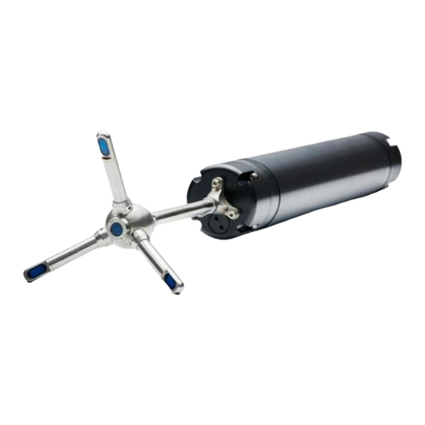
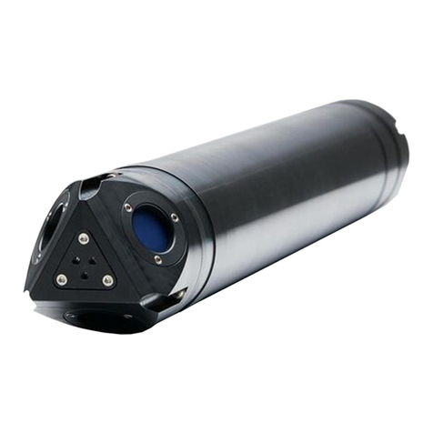
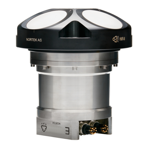
Nortek Signature VM User manual

Signature VM Operations Manual
N3015-026500 | V 1.1
V 1.4
````````

2
NORTEK
Table of Contents
Table of Contents ............................................................................................................................................ 2
1System Overview .....................................................................................................................................6
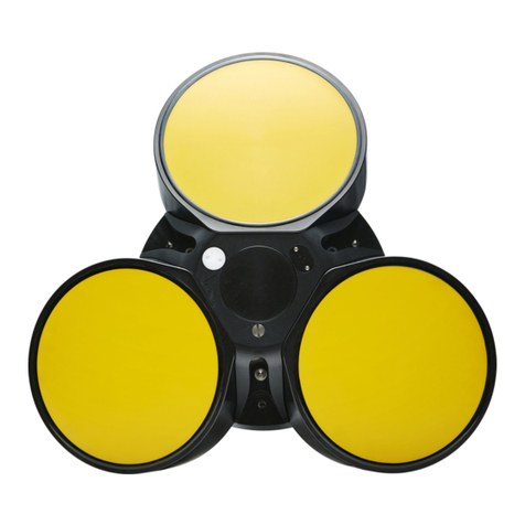
1.1 Signature AD2CP Sensor................................................................................................................7
1.2 GNSS Receiver ...............................................................................................................................7
1.3 Data acquisition system...................................................................................................................8
2Getting Started .........................................................................................................................................9
2.1 Checking the Inventory....................................................................................................................9
2.2 Signature VM Software....................................................................................................................9
2.3 Interface...........................................................................................................................................9
2.3.1 24VDC Version............................................................................................................................9
2.3.2 AC version.................................................................................................................................10
2.4 Connecting the parts .....................................................................................................................10
2.4.1 Connecting the Signature Sensor..............................................................................................10
2.4.2 GNSS Connection .....................................................................................................................13
2.4.3 Computer connections...............................................................................................................15
2.4.4 Power On...................................................................................................................................16
2.4.5 Power Off...................................................................................................................................16
2.4.6 Connecting to the Computer......................................................................................................16
3Acquisition Software...............................................................................................................................19
4.1 Checking the system .....................................................................................................................21
5Measuring...............................................................................................................................................25
5.1 Configuration .................................................................................................................................25
5.2 Start the measurement..................................................................................................................27
5.3 Measuring and Display..................................................................................................................29
5.4 Status.............................................................................................................................................29
5.5 Track display..................................................................................................................................30
5.6 Echograms.....................................................................................................................................32
5.7 Keyboard Shortcuts.......................................................................................................................32
5.8 Error Messages .............................................................................................................................32
6Offsets....................................................................................................................................................34
6.1 Vessel Coordinate system.............................................................................................................34
6.2 Horizontal and vertical offsets .......................................................................................................35
6.3 Orientation of the GNSS and Signature ........................................................................................37
7Output.....................................................................................................................................................39
7.1 NMEA Output.................................................................................................................................39
7.1.1 $SDDBT –Echosounder- Depth Below Transducer..................................................................39
7.1.2 $SDGGA - Global Positioning System Fix Data........................................................................40
7.1.3 $SDVTG - Track made good and Ground speed......................................................................40
7.1.4 $PNORI1 –General Information ...............................................................................................40

3
7.1.5 $PNORS1 –Sensor Data..........................................................................................................42
7.1.6 $PNORCV –Velocity data per Cell ...........................................................................................42
7.1.7 $PNORC1 –Velocity data per Cell............................................................................................42
7.1.8 $PNORBT4 –Speed over ground and depth............................................................................43
7.1.9 $VDVDR –Current Speed and Direction ..................................................................................43
8Installation ..............................................................................................................................................44
8.1 Instrument orientation....................................................................................................................44
8.2 Mounting Considerations...............................................................................................................44
8.2.1 Bubbles......................................................................................................................................44
8.2.2 Grounding..................................................................................................................................44
8.2.3 Ship movements........................................................................................................................45
8.2.4 Ship generated flow fields .........................................................................................................45
8.2.5 Over the Side Mounting.............................................................................................................46
9Maintenance...........................................................................................................................................50
9.1 Signature Sensor...........................................................................................................................50
9.2 Biofouling.......................................................................................................................................50
9.2.1 Antifouling Paint and patches....................................................................................................50
9.3 Instrument Care.............................................................................................................................50
9.4 Connector Care .............................................................................................................................51
9.5 Cable Care.....................................................................................................................................51
10 Troubleshooting......................................................................................................................................52
10.1 Remote Support through TeamViewer..........................................................................................52
10.2 Communication..............................................................................................................................53
10.2.1 Cable .........................................................................................................................................53
10.3 Power.............................................................................................................................................53
10.3.1 Interface does not switch on......................................................................................................53
10.3.2 Power to the Signature sensor..................................................................................................53
11 Computer configuration..........................................................................................................................54
12 GNSS .....................................................................................................................................................56
12.1 Filter setting...................................................................................................................................56
12.2 Increasing the accuracy using RTK (NTRIP) ................................................................................56
13 Glossary .................................................................................................................................................58
14 Connector Pin Configurations ................................................................................................................60

4
NORTEK
Preface
This manual is designed to help users of Signature VM to get familiar with the system. The manual includes
chapters covering how to get the system up and running as quickly as possible, functional testing, software
information, and tips for maintenance and troubleshooting.
This manual is for the Signature VM System. For details on the individual instruments please refer to the
specific manuals that come with the sensor itself.
Nortek WEB
At our website, http://www.nortekgroup.com, you will find technical support, user manuals, and the latest
software and firmware. General information, technical notes and user experience can also be found here.
Your feedback is appreciated
If you find errors, omissions or sections poorly explained, please do not hesitate to contact us. We
appreciate your comments and your fellow users will as well.
Contact Information
We recommend first contacting your local sales representative before the Nortek main office. If you need
more information, support or other assistance, you are always welcome to contact us or any of our
subsidiaries by email, phone or fax.
Email mailto:support@nortekgroup.com (for technical support questions)
Phone: +31 20 6543600
You can also write us at:
Nortek BV
Schipholweg 333a
1171PL Badhoevedorp, The Netherlands.
Manual Revision - N3015-026500
Version
Date
Supports Software
version
Notes
Preliminary
01.02.2018
1.2
Version 1
11.04.2018
1.5
Version 1.1
11.09.2018
1.6
Interface Version 2 (1/2 19 inch)
Version 1.2
21.12.2018
1.7
Version 1.3
29.03.2019
1.8
Version 1.4
11.07.2019
1.9

5
Health and safety
The system is designed and produced to comply with the council directive of
2014/108/EC relating to electromagnetic compatibility. The design is according to RoHS
II directive 2011/65/EU
The mark on the left is in compliance with the Waste Electronic Equipment Directive
2012/19/EU (WEEE). It is a requirement NOT to dispose the equipment as unsorted
municipal waste but use the return to collection systems according to local law, or return
to the Nortek facilities.
Relevant plastic parts on the Signature sensor are marked for end-of-life recycling
(Directive 2008/98/EC on waste)
Use the following safety guidelines to help ensure your own personal safety
and to help protect your equipment and working environment from potential damage
General Power Safety for the 4411 Interface unit and Computer
Observe the following guidelines when connecting your equipment to a power source:
•Check the voltage rating before you connect the equipment to an electrical
outlet to ensure that the required voltage and frequency match the available
power source.
•Do not plug the equipment power cables into an electrical outlet if the power
cable is damaged.
•To prevent electric shock, plug the equipment power cables into properly
grounded electrical outlets. Do not use adapter plugs that bypass the grounding
feature or remove the grounding feature from the plug or adapter.
•Do not operate your equipment with any cover(s) removed.
•Unplug this apparatus during lightning storms or when unused for long periods
of time.
•Do not expose the unit to rain or an environment where it may be splashed by
water or other liquids, as doing so may result in fire or electric shock.
System Safety
•The system is designed to be used on a moving vessel. Make sure that all parts
are well secured, and nothing can come loose when exposed to heavy
vibrations or sudden movements which may occur aboard a vessel.
Safety when installing and operating the Signature VM Sensor
•When mounting the Signature sensor on any vessel or other platform, be careful
to follow proper precautions and safe-work procedures as applicable to working
with medium-weight, long, unwieldy material (work-gloves, helmet, and if on-
board, possibly life-jacket).
•Ensure that nothing rests on your equipment's cables and that the cables are
not located where they can be stepped on or tripped over.

6
NORTEK
1 System Overview
The Signature VM system is a highly integrated system with the sole purpose of accurately measuring
vertical profiles of the water’s velocity and direction from a moving platform.
Velocity of the water is measured using a Signature series sensor. The Signature sensors are advanced
five-beam current profiling systems. Built on the entirely new AD2CP platform, they are designed for
unprecedented performance in high energy turbulent environments. The Signature also measures its own
speed and direction across the bottom of the channel using a technique known as ‘bottom tracking’
Position and movement of the moving platform (usually a vessel) is recorded using a high precision Global
Navigation Satellite System (GNSS) receiver, which also provides accurate timing. By combining the
measured movements from both the GNSS and bottom track it is possible to correct the measured water
velocities for the movement of the platform itself.
A dedicated computer system with Signature VM software collects the data, takes care of accurate timing
and continuously monitors the quality of the data. Since no additional data from any external sensors is
required and the computer comes fully configured, the whole system is basically ‘Plug and Play’
Figure 1 Complete system overview
Signature VM Computer
PoE
adapter
Ethernet
Switch
Eth1
USB
Pwr (90-
230VAC)
Interface Box
Signature Sensor
GNSS
User supplied Laptop or PC
with Remote Desktop
Eth2
90 - 260VAC
48 VDC
PSU
LED Driver
48 VDC
DC/DC
12-36 VDC
DC Option
AC Option
90 - 230VAC

7
1.1 Signature AD2CP Sensor
The figures below show the Signature1000 system but can be easily translated to the Signature500. The
Signature1000 and Signature500 sensor heads have five acoustic transducers, four slanted at 25 degrees
from vertical, and a fifth vertical beam. For dimensions, please refer to the specific instrument data sheet,
available for download from our website.
The pressure sensor, temperature sensor and LED light are all visible from the outside. Note also the beam
configuration, with beam one pointing in the positive X-axis (see the engraved axis definition on the head)
Figure 2 Signature Transducers and sensors
Power requirements:
DC input: 12-48 (Sig500/1000)
For more details on the Signature Sensor itself, please refer to the Signature Manual, as available on the
Nortek group website: http://www.nortekgroup.com/manuals-quick-guides
1.2 GNSS Receiver
Figure 3 GNSS - Receiver

8
NORTEK
The Advanced Navigation Global Navigation Satellite System (GNSS) receiver is a fully integrated, certified
navigation and heading solution. It provides high accuracy position, velocity and heading information and
does not require any calibrations or setup. It can provide accurate heading even during GNSS outages (for
up to 20 minutes). This is possible as a result of the INS (Inertial Navigation System) integration in the unit.
The antenna is equipped with two internal GNNS receivers and its heading is not subject to magnetic
interference. The vessel doesn’t have to move to provide an accurate heading.
The built-in PTP (Precision Time Protocol) server provides an accurate timing reference for the whole
system.
The GNSS is powered through the Ethernet cable.
For more details on the GNSS Sensor itself, please refer to the User Manual, as available on: the Advanced
Navigation Website: https://www.advancednavigation.com/product/gnss-compass You can also check out
the latest firmware release here.
1.3 Data acquisition system
Figure 4 Signature VM Data acquisition and interface
Data is collected using a computer running the ‘Signature VM’ software. The Signature VM interface box
provides all necessary connection and power to the individual instruments. The total system is 19” rack
mountable. It can be controlled using a local keyboard and monitor, or from a remote location over Ethernet.

9
2 Getting Started
This chapter deals with installation of the accompanying software, connecting to the instrument and other
information that is important for first time use of the instrument.
2.1 Checking the Inventory
Check the content of the received package against the packing list included in the shipment. Do not hesitate
to contact us if you find any part of the delivery missing.
2.2 Signature VM Software
The Signature VM software is under continuous development, so it is advised to check on a regular basis if
a new version is available. Note that a decent internet connection is required for checking and possible
downloads.
2.3 Interface
The Signature VM interface provides power to the Signature sensor and GNSS and has all necessary
interconnections between the different parts. Two versions are available: an AC version that accepts
standard mains power from 100 to 240 VAC and a 24 VDC version that can take a DC voltage from 12 to 36
VDC
Figure 5 Rear panel connections. AC version
2.3.1 24VDC Version
The 24 VDC version is powered through a 3 Pin XLR connector. Use a suitable power lead with a 3 pin
female XLR connector.(Neutrik model NC3FXX-B)
The unit is reverse polarity protected, so reversing the power lines will not damage it. The supply is fused
using the fuse on the rear-panel.
+
-
DC Connector on rear panel
1: -
2: + 12-34 VDC
3: Shield (to housing)

10
NORTEK
The unit will work with any voltage between 12 and 34 VDC, but 24VDC is preferred. When using 12VDC,
current surges of up to 1.5 A may occur, so the required power lines should have a low ohms resistance.
2.3.2 AC version
The AC version can take mains power ranging from 100 to 240 VAC. Power is connected using a standard
IEC mains socket on the rear. The socket contains two 1.6AT fuses.
2.4 Connecting the parts
A Signature VM system basically consists of three parts: a Signature sensor, a GNSS and a computer. The
interface box contains all necessary interconnections and power supplies for the other parts.
Figure 6 Connecting the interface to the PC
Note that only one ethernet port on the PC is configured to connect to the Signature VM Interface. The
system will not work if this is connected to the wrong port!
The second ethernet port may be connected to the local network and is only used to access the internet.
2.4.1 Connecting the Signature Sensor
The Signature sensor is connected through its Ethernet interface. This is the 6-Pin connector on the sensor.
The 8-Pin connector is not used in this configuration and should be fitted with a ‘dummy’ connector.
USB
Ethernet

11
Figure 7 Signature Sensor connections
When mating the SubConn connectors pay attention to the following guidelines:
•Connectors must be greased with Molykote 44 Medium before every mating. A small amount of
grease is supplied with the system.
•A layer of grease corresponding to minimum 1/10 of socket depth should be applied to the female
connector
•The inner edge of all sockets should be completely covered, and a thin transparent layer of grease
left visible on the face of the connector
•After greasing, fully mate the male and female connector in order to secure optimal distribution of
grease on pins and in sockets
•To confirm that grease has been sufficiently applied, de-mate and check for grease on every male
pin. Then re-mate the connector
6 pin Ethernet + Power
8-pin Serial
(NOT USED)
Recommended level of grease

12
NORTEK
The other end of the power-signal cable has a metal shield Ethernet connector that fits the connector on the
rear of the box. Insert the connector until it clicks into lock. To release the connector, press the ‘PUSH’ lever
and gently pull the connector housing.
The standard Signature cable comes with a simple jack plug. On the interface that power is supplied through
a DC-Power plug with lock-nut. An adapter cable is supplied to connect the standard signature cable to the
interface. Lock it by tightening the nut.
Figure 8 Signature Power and data connection

13
2.4.2 GNSS Connection
The GNSS is supplied with a 20 m Ethernet cable. One end has a small plastic connector with a bayonet
lock which goes to the GNSS unit.
When connecting first check the orientation of the Ethernet connector. Then push in while holding the plastic
locking-ring. Push the ring while turning it clockwise until it clicks to lock. It is a bayonet lock, so it should not
need more than a 30~40 degrees rotation. This may take considerable force, and it is best to use the
supplied 'Connector wrench’
Figure 9 Connecting the GNSS connector
The other end of the cable has a large plastic Ethernet connector that fits the one on the rear of the interface
box. This bayonet lock may be difficult to lock when new.
Power to the GNSS is supplied through the Ethernet cable, so no additional power connection is needed
here.

14
NORTEK
Figure 10 Connecting the GNSS to the interface

15
2.4.3 Computer connections
Next to the GNSS connector is the main Ethernet port and a USB port which have to be connected to the
Signature VM computer.
Figure 11 All interface connections
Power to Signature
Data to Signature
Power and Data
to GNSS
LAN and USB to
computer
Power in

16
NORTEK
2.4.4 Power On
Switch the computer on by pressing the main button on the front-panel for a second and then release it. The
interface has a simple ‘ON’ switch and may be switched on before or after switching the computer.
2.4.5 Power Off
When powering the system off, first switch off the computer using the power down menu, or by using the
switch. Then switch off the interface.
2.4.6 Connecting to the Computer
Though it is possible to connect to the Signature VM PC using a keyboard/mouse/monitor, the general idea
is to use a remote desktop connection from a laptop. (Not supplied with the system)
Any computer that can run the Remote desktop client can be used to connect to the system. Remote
desktop clients are available for Windows, Macintosh and Linux.
The client computer can be connected to the Ethernet connector on the front panel of the interface, and
configured as follows.
(note: configuration example shown here for Windows 10)
First make sure the Ethernet adapter is configured for ‘Obtain an IP address automatically’. (Control Panel-
>Network and Internet->Network Connections)
1
2
NOTE: depending on the computer model, this switch
may look different, or even be in a different position.

17
Now connect the client computer to the interface, and then open ‘Remote Desktop’ (Hit the ‘Windows’ key,
and just type ‘remote desktop’)

18
NORTEK
The address of the Signature VM PC is fixed to 192.168.100.1. The user name is ‘SurveyVM’. You can now
click ‘Save As’ to save this connection for later.
Click connect. If all is correct, a popup will appear asking for the password. The password is ‘SurveyVM’
Once connected the screen of the Signature VM computer will appear:
IP : 192.168.100.1
User: SurveyVM
Passw: SurveyVM

19
3 Acquisition Software
Once everything is connected, start the Signature VM software.
Each window may be moved, rescaled or closed if required. To recover a window, or to reset the screen
layout to defaults, click on one of the four window recovery buttons in the lower left. Clicking the appropriate
button will bring up the related window, or you can click ‘Restore Layout’ to get back to default.
The main task bar is on the left. This contains the controls for starting and stopping the measurement,
changing the settings and replaying the data.
Window recovery buttons

20
NORTEK
Figure 12 Taskbar explained
Connect / Disconnect the instruments
Start/Stop the measurement
Instrument connection options
Open a file for playback
Start / Stop playback
Pause playback
Playback options
Start a new recording
Recording details
Start NMEA output
NMEA output settings
Configuration
Table of contents
Other Nortek Measuring Instrument manuals

Nortek
Nortek Vector User manual

Nortek
Nortek Vectrino Profiler User manual

Nortek
Nortek Vectrino User manual

Nortek
Nortek DVL 1000 300m User manual

Nortek
Nortek Signature55 User manual

Nortek
Nortek AWAC User manual

Nortek
Nortek Aquadopp User manual

Nortek
Nortek Vectrino User manual

Nortek
Nortek Vector User manual

Nortek
Nortek Aquadopp Profiler User manual
Popular Measuring Instrument manuals by other brands

Siemens
Siemens SITRANS F M Technical documentation

ATI Technologies
ATI Technologies 2H Installation and operation manual

PlantCare
PlantCare Plant Thirsty Light user manual

PR electronics
PR electronics PRetrans 5115 Series manual

AKCP
AKCP SensorProbe2 PLUS Introduction manual

Eclipse
Eclipse EGA2 Combustion instruction manual