DIEBOLD NIXDORF P1200 User manual
P1200 Thermal Printer
User Manual
01750352498 C
Customer/Partner Use
This document is property of Diebold Nixdorf and is intended for customer/partner use. A written
license agreement with Diebold Nixdorf is not required to use this material.

Copyright © Diebold Nixdorf. Copyright protection is claimed for each revision listed in the document his-
tory, as of the date indicated. All Rights Reserved.
This document contains proprietary information of Diebold Nixdorf, Incorporated or its subsidiaries (col-
lectively “Diebold Nixdorf“) and may include information that is protected by copyright, trademark and
patent laws in the US, Germany, and globally. All rights, including rights created by patent grants or reg-
istration of a utility model or design, are reserved.
No part of this document may be translated, reproduced, stored in a retrieval system, or transmit-
ted, in any form or by any means: electronic, mechanical, photocopying, recording, or otherwise,
without prior written permission from Diebold Nixdorf. Any violations of the foregoing may give
rise to a claim for damages.
If the document pages state the information is confidential (or words of similar import), then this
document is intended solely for the use of the employees or other personnel of Diebold Nixdorf
unless expressly authorized in writing by Diebold Nixdorf. Other uses of this information without
the express written consent of Diebold Nixdorf are prohibited.
This document should be treated as confidential material for security reasons. Any unauthorized
disclosure or use of confidential material may violate the U.S. Theft of Trade Secrets provisions
of Section 1832 of Title 18 of the United States Code as well as comparable laws in other jurisdic-
tions throughout the world, and may be punishable by fine and imprisonment.
This document and the information contained herein are provided AS IS AND WITHOUT WARRANTY.
In no event shall Diebold Nixdorf or its suppliers be liable for any special, indirect, or consequential dam-
ages of any nature resulting from the use of information in this manual. The information contained in this
document is subject to change without notice. When using the document for system implementation,
please call your authorized Diebold Nixdorf sales or service representative for any applicable changes.
Any trademarks, service marks, product names or company names not owned by Diebold Nixdorf, that
appear in this document are used for informational purposes only, and Diebold Nixdorf claims no rights
thereto, nor does such use indicate any affiliation with or any endorsement of Diebold Nixdorf or Diebold
Nixdorf products by the owners thereof.
Your use of this document and/or any of the information contained herein constitutes your agreement to
all of the terms stated on this page.
Copyright © 2022, Diebold Nixdorf
01750352498 C
ii

Table of Contents
1 Manufacturer's Declaration and Approval............................................................................... 1-1
2 Supplier’s Declaration of Conformity ...................................................................................... 2-1
3 Signs, Markings and Symbols .................................................................................................. 3-1
4 Section-Specific Warning Notes............................................................................................... 4-1
5 Safety Summary......................................................................................................................... 5-1
6 Important Information to the User............................................................................................ 6-1
7 Unpacking................................................................................................................................... 7-1
8 Product Overview ...................................................................................................................... 8-1
8.1 Introduction ........................................................................................................................8-1
8.2 Features .............................................................................................................................8-1
8.3 Applicable Model................................................................................................................8-2
8.4 Accessories........................................................................................................................8-2
9 Specifications............................................................................................................................. 9-1
9.1 General ..............................................................................................................................9-1
9.2 Environmental Usage Conditions.......................................................................................9-3
9.3 Internal Buffers...................................................................................................................9-4
9.4 Thermal Head Basic Performance .....................................................................................9-4
9.5 Main Card...........................................................................................................................9-4
9.6 Option Interface Card.........................................................................................................9-5
9.7 Reliability............................................................................................................................9-5
9.8 Options...............................................................................................................................9-6
9.9 Paper Specifications ..........................................................................................................9-7
10 Description ................................................................................................................................. 10-1
10.1 Overall view........................................................................................................................10-1
10.2 LED and paper feed key ....................................................................................................10-2
10.3 ON/OFF switch...................................................................................................................10-3
10.4 Connectors.........................................................................................................................10-4
11 Set Up Procedure....................................................................................................................... 11-1
11.1 Requirements for Operation...............................................................................................11-1
11.2 Setting up the Printer .........................................................................................................11-3
11.3 Turning off the Printer ........................................................................................................11-3
12 Installation Procedure ............................................................................................................... 12-1
12.1 Connecting the Power Cord and Interface Cable...............................................................12-1
12.1.1 Connect to Power Adapter.................................................................................. 12-2
12.1.2 Connect via standard USB Type-B Cable........................................................... 12-2
12.1.3 Connect via Option Card (RS232 & LAN)........................................................... 12-3
12.1.4 Connect via Y-Cable ........................................................................................... 12-10
12.1.5 Connecting via Cash Drawer .............................................................................. 12-10
12.1.6 Interface cable to POS terminal connection position .......................................... 12-10
Copyright © 2022, Diebold Nixdorf
01750352498 C
iii

Table of Contents
12.2 Choosing a Location ..........................................................................................................12-11
12.2.1 Table Top, Horizontal Orientation ....................................................................... 12-11
12.2.2 Wall Mounted, Vertical Orientation ..................................................................... 12-12
12.3 Replacing the paper roll .....................................................................................................12-14
13 Diagnostics................................................................................................................................. 13-1
13.1 Offline Diagnostic ...............................................................................................................13-1
14 Cleaning...................................................................................................................................... 14-1
14.1 Cleaning the Covers...........................................................................................................14-1
14.2 Cleaning the Thermal Print Head.......................................................................................14-1
15 Troubleshooting......................................................................................................................... 15-1
15.1 Clearing a paper jam..........................................................................................................15-1
15.2 Resetting cutter failure or jam ............................................................................................15-2
15.3 Common Problems and Solutions......................................................................................15-5
15.4 LED Indication Table..........................................................................................................15-7
16 Appendix..................................................................................................................................... 16-1
16.1 Ethernet..............................................................................................................................16-1
16.2 Web Setting Page ..............................................................................................................16-1
16.3 Paper Length......................................................................................................................16-3
16.4 Sensor Calibration Value ...................................................................................................16-3
16.5 Tested Paper......................................................................................................................16-4
Copyright © 2022, Diebold Nixdorf
01750352498 C
iv

Table of Contents
List of Tables
Table 3-1 Warning signs used................................................................................................3-1
Table 3-2 Mandatory signs used ............................................................................................3-1
Table 9-1 Normal operation....................................................................................................9-3
Table 9-2 Idle mode................................................................................................................9-3
Table 9-3 Extreme operating range........................................................................................9-3
Table 9-4 Storage...................................................................................................................9-3
Table 9-5 Transit ....................................................................................................................9-3
Table 9-6 Paper specifications ...............................................................................................9-8
Table 16-1 Tested Paper..........................................................................................................16-4
Copyright © 2022, Diebold Nixdorf
01750352498 C
v

1
1 Manufacturer's Declaration and Approval
Interference suppression and electrical safety
NOTE
Note concerning radio interference suppression
This is a Class A configuration. This configuration may cause radio interference in resi-
dential areas. If this is the case, then the operator may be required to implement suit-
able remedial measures
All other devices connected to this product must comply with the EMC Directive 2014/30/EU and the Low
Voltage Directive 2014/35/EU.
FCC-Class A Declaration
This equipment has been tested and found to comply with the limits for a Class A digital device, pursuant
to part 15 of the FCC Rules. These limits are designed to provide reasonable protection against harmful
interference when the equipment is operated in a commercial environment. This equipment generates,
uses, and can radiate radio frequency energy and, if not installed and used in accordance with the in-
struction manual, may cause harmful interference to radio communications. Operation of this equipment
in a residential area is likely to cause harmful interference in which case the user will be required to cor-
rect the interference at his own expense. Modifications not authorized by the manufacturer may void
users authority to operate this device.
FCC Caution: Any changes or modifications not expressly approved by the party responsible for compli-
ance could void the user's authority to operate this equipment.
This transmitter must not be co-located or operating in conjunction with any other antenna or transmitter.
CAN ICES-3 (A)/NMB-3 (A)
The device complies with the requirements of the EEC directive 2014/30/EU with regard
to ‘Electro-magnetic compatibility" and 2014/35/EU “Low Voltage Directive” and RoHS
directive 2011/65/EU.
Therefore, you will find the CE mark on the device or packaging.
In addition, the P1200 has received the cTUVus symbol.
Copyright © 2022, Diebold Nixdorf
01750352498 C
1-1

Manufacturer's Declaration and Approval
The following information is for EU-member states only:
Disposal of products
(based on EU-Directive 2012/19/EU)
Directive on Waste electrical and electronic equipment – WEEE)
The use of the symbol indicates that this product may not be disposed as unsorted munici-
pal waste and has to be collected separately. Integrated batteries and accumulators can be
disposed of with the product. They will be separated at the recycling centers.
The black bar indicates that the product was placed on the market after August 13, 2005.
By ensuring this product is disposed of correctly, you will help prevent potential negative
consequences for the environmental and human health, which could otherwise be caused
by inappropriate waste handling of this product.
For more detailed information about the take-back and recycling of this product, please con-
tact your supplier where you purchased this product.
Changes or modifications not expressly approved by the manufacturer for compliance could void the
User’s authority to operate the equipment.
Copyright © 2022, Diebold Nixdorf
01750352498 C
1-2

2
2 Supplier’s Declaration of Conformity
Product Description: Thermal Printer
Model: P1200
Party issuing Supplier’s Declaration of Conformity
Diebold Nixdorf Singapore PTE. LTD.
30A Kallang Place
#04-01
Singapore 339213
Phone: +65 6747 3828
Responsible Party – U.S. Contact Information
Diebold Nixdorf
5995 Mayfair Road
N. Canton, OH 44720 / USA
Phone: +1 330 490 5049
FCC Compliance Statement (for products subject to Part 15)
This device complies with Part 15 of the FCC Rules. Operation is subject to the following two conditions:
(1) This device may not cause harmful interference, and
(2) this device must accept any interference received, including interference that may cause undesired
operation.
Copyright © 2022, Diebold Nixdorf
01750352498 C
2-1
3
3 Signs, Markings and Symbols
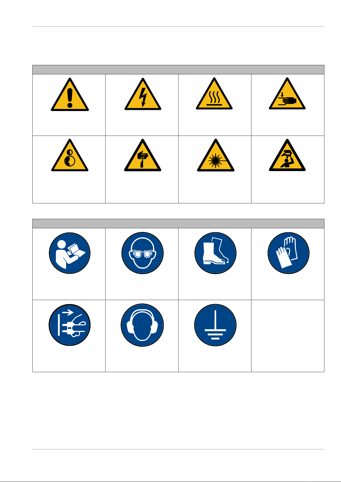
Table3-1: Warning signs used
Warning signs
General
warning sign
Warning of
electrical voltage
Warning of
hot surface
Warning of
hand injuries
Warning of
counter-rotating
rollers
Warning of
sharp
object
Warning of
laser radiation
Warning of
obstacles
in the head area
Table3-2: Mandatory signs used
Mandatory signs
Observe
the manual
Wear
eye protection
Wear
foot protection
Wear
hand protection
Pull
main plug
Wear
ear protection
Ground
before use
Copyright © 2022, Diebold Nixdorf
01750352498 C
3-1

4
4 Section-Specific Warning Notes
DANGER
This warning note describes a hazard with a high degree of risk which, if not avoided,
will result in death or grave bodily injury.
WARNING
This warning note describes a hazard with a medium degree of risk which, if not
avoided, could result in death or grave bodily injury.
CAUTION
This warning note describes a hazard with a low degree of risk which, if not avoided,
could result in slight or minor bodily injury.
NOTE
This note provides application tips and information that help prevent errors and material
damage.
Copyright © 2022, Diebold Nixdorf
01750352498 C
4-1
5
5 Safety Summary
Personal safety in handling or maintaining the equipment is extremely important. Warnings and Cautions
necessary for safe handling are included in this manual. All warnings and cautions contained in this man-
ual should be read and understood before handling or maintaining the equipment.
Do not attempt to effect repairs or modifications to this equipment. If a fault occurs that cannot be recti-
fied using the procedures described in this manual, turn off the power supply, unplug the machine, and
then contact your authorized Diebold Nixdorf representative for assistance.
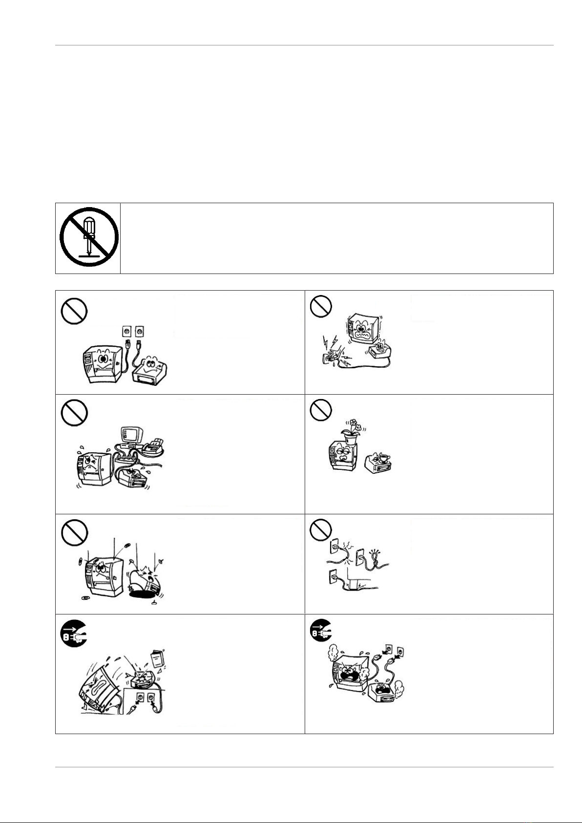
This symbol indicates prohibited actions (prohibited items).
Specific prohibited contents are drawn inside or near the symbol.
(The symbol on the left indicates “no disassembling”.)
Any other than the
specified AC voltage is
prohibited.
Do not use voltages other than the
voltage (AC) specified on the rating
plate, as this may cause fire or
electric shock.
Prohibited Do not plug in or unplug the power cord plug with
wet hands as this may cause electric shock.
If the machines share the same outlet
with any other electrical appliances
which consume large amounts of
power, the voltage will fluctuate widely
each time these appliances operate.
Be sure to provide an exclusive outlet
for the machine as this may cause the
machines to malfunction.
Prohibited
Prohibited Do not place metal objects or water-filled
containers such as flower vases, flower pots or
mugs, etc. on top of the machines. If metal
objects or spilled liquid enter the machines, this
may cause fire or electric shock.
Prohibited Do not insert or drop metal,
flammable or other foreign objects
into the machines through the
ventilation slits, as this may cause fire
or electric shock.
Prohibited Do not scratch, damage or modify the power
cords. Also, do not place heavy objects on, pull
on, or excessively bend the cords, as this may
cause fire or electrical shock.
Disconnect
the plug.
If the machines are dropped or their
cabinets damaged, first turn off the
power switches and disconnect the
power cord plugs from the outlet,
and then contact your authorized
Diebold Nixdorf representative for
assistance. Continued use of the
machine in that condition may cause
fire or electric shock.
Disconnect
the plug.
Continued use of the machines in an abnormal
condition such as when the machines are
producing smoke or strange smells may cause
fire or electric shock. In these cases,
immediately turn off the power switches and
disconnect the power cord plugs from the outlet.
Then, contact your authorized Diebold Nixdorf
representative for assistance.
Copyright © 2022, Diebold Nixdorf
01750352498 C
5-1

Safety Summary
Disconnect
the plug.
If foreign objects (metal fragments,
water, and liquids) enter the
machines, first turn off the power
switches and disconnect the power
cord plugs from the outlet, and then
contact your authorized Diebold
Nixdorf representative for assistance.
Continued use of the machine in that
condition may cause fire or electric
shock.
Disconnect
the plug. When unplugging the power cords, be sure to hold
and pull on the plug portion. Pulling on the cord
portion may cut or expose the internal wires and
cause fire or electric shock.
Connect a
grounding wire.
Ensure that the equipment is properly
grounded. Extension cables should
also be grounded. Fire or electric
shock could occur on improperly
grounded equipment.
No
disassembling. Do not remove covers, repair or modify the
machine by yourself. You may be injured by high
voltage, very hot parts or sharp edges inside the
machine.
Copyright © 2022, Diebold Nixdorf
01750352498 C
5-2

Safety Summary
Precautions
The following precautions will help to ensure that this machine will continue to function correctly.
• Try to avoid locations that have the following adverse conditions
– Temperatures out of the specification
– Direct sunlight
– High humidity
– Shared power source
– Excessive vibration
– Dust/Gas
• The cover should be cleaned by wiping with a dry cloth or a cloth slightly dampened with a mild de-
tergent solution. NEVER USE THINNER OR ANY OTHER VOLATILE SOLVENT on the plastic cov-
ers.
• USE ONLY DIEBOLD NIXDORF SPECIFIED paper.
• DO NOT STORE the paper where they might be exposed to direct sunlight, high temperatures, high
humidity, dust, or gas.
• Ensure the printer is operated on a level surface or vertical wall.
• Any data stored in the memory of the printer could be lost during a printer fault.
• Try to avoid using this equipment on the same power supply as high voltage equipment or equipment
likely to cause mains interference.
• Unplug the machine whenever you are working inside it or cleaning it.
• Keep your work environment static free.
• Do not place heavy objects on top of the machines, as these items may become unbalanced and fall
causing injury.
• Do not lean against the machine. It may fall on you and could cause injury.
• Care must be taken not to injure yourself with the printer paper cutter.
• Unplug the machine when it is not used for a long period of time.
Copyright © 2022, Diebold Nixdorf
01750352498 C
5-3

6
6 Important Information to the User
In order to ensure compliance with the Product Safety, FCC marking requirements, you must use the
power supply, power cord, and interface cable which were shipped with this product or which meet the
following parameters:
Power Adapter
The power adapter is required to comply with the safety and/or EMC requirements depending on the
county where the equipment is used, and to have the following electrical characteristics, Class 1 power
adapter with SELV (Secondary Extra Low Voltage), input rated 100-240 Vac, 2.0A Max, 50/60 Hz, output
rated 24 Vdc, 2.6A.
Interface Cable
You are advised to use a shielded (360 degree) interface cable with this product. The shield must be
connected to the frame or earth ground connection or earth ground reference at BOTH ends of the ca-
ble. If another cable is used than described above you will need to test this cable with the Diebold
Nixdorf printer and your system for local EMC requirements where the equipment is used.
Power Cord
For this product a UL listed, detachable power cord is required. When the power supply is mounted on
the floor, a power cord with Type SJT marking is required. If a power cord is used different from de-
scribed above, you might violate safety certifications which are in force in the country of use. The socket-
outlet needs to be installed near the equipment and must be easily accessible.
Power Cord
As the power cord is not supplied with this printer, locally purchase the power cord that meets the follow-
ing standard.
For USA and Canada:
Power Cord – UL and CSA approved, type SVT, 18/3AWG, rated min. 125V, 10A
Attached Plug and Appliance Coupler – UL and CSA approved, molded on type.
The plug is parallel-blade grounding type, NEMA 5-15P configuration. The appliance coupler is Female
configuration.
Both attachment plug and appliance coupler are rated minimum 125V, 10A.
For European countries:
Power Supply Cord – HAR or domestic approved where the equipment is used,
Type H05VV-F, rated minimum 250V, 10A.
Attachment Plug and Appliance Coupler – Domestic approved where the equipment is used, molded on
type, having grounding terminal rated minimum 250V, 10A. The appliance coupler is Female configura-
tion.
Copyright © 2022, Diebold Nixdorf
01750352498 C
6-1
7
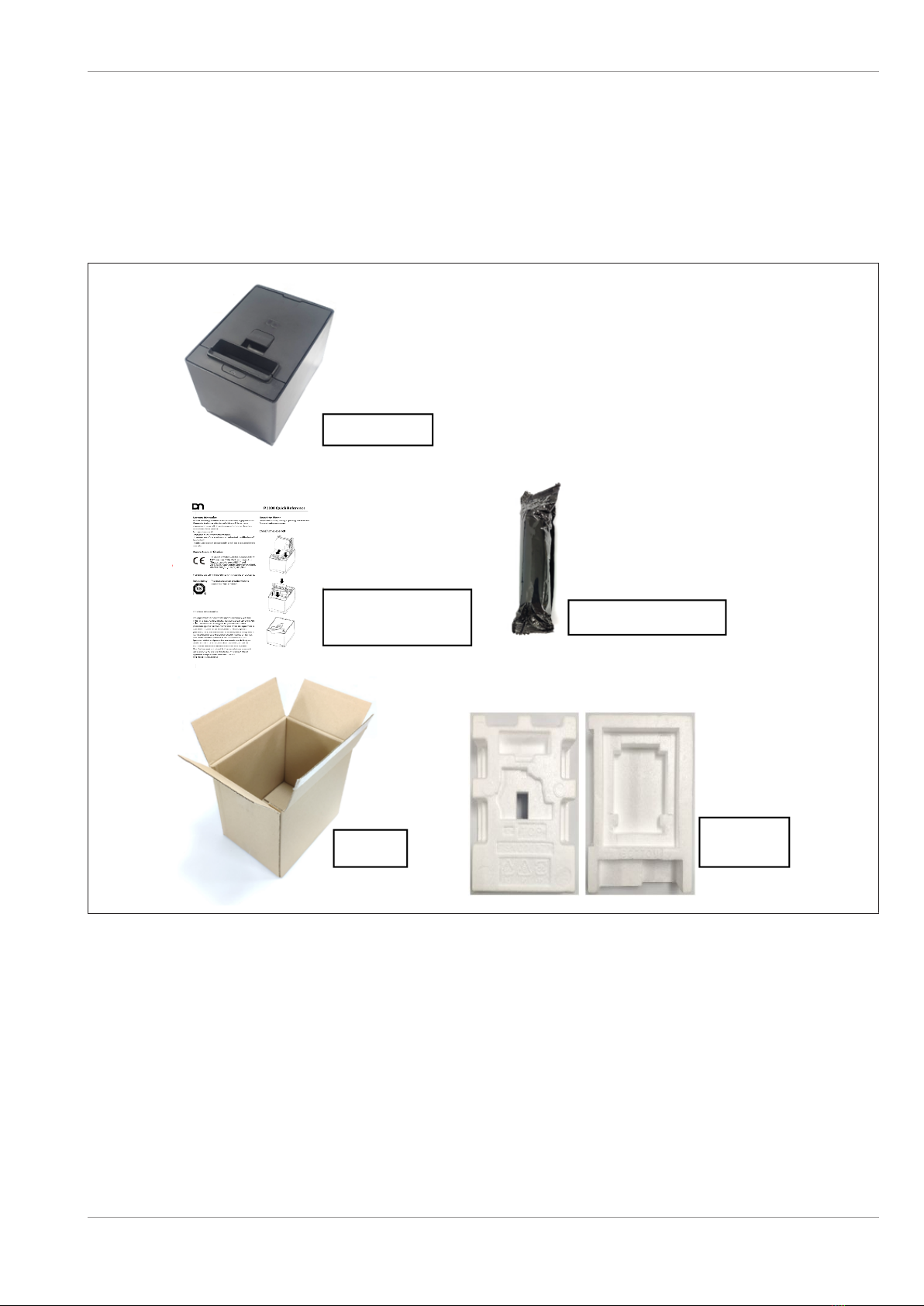
7 Unpacking
1. Open the carton.
2. Remove the printer from the carton.
3. Check the content and make sure no missing parts.
4. Place the printer on a level surface and make sure no physical damage.
Printer
Quick Installation
Manual Starter Roll
Carton Protector
Pack
NOTICE!Keep the original carton and protector pack for future transportation of the printer.
Copyright © 2022, Diebold Nixdorf
01750352498 C
7-1

8
8 Product Overview
8.1
8.1 Introduction
This product consists a thermal head for one side printing. Base model includes a 32bit CPU architecture
with Flash ROM, Cash Drawer Connector, Mini-DIN Power, USB Type B connector and expansion con-
nector. The expansion connector is compatible with Power USB I/F, and RS232 I/F or Ethernet I/F as op-
tion.
This manual contains general set-up and maintenance information and should be read carefully to help
gain the maximum performance and life from your printer. For most queries please refer to this manual
and keep it safe for future reference.
8.2
8.2 Features
• Drop-in paper loading
• Paper out sensor
• Paper jam sensor (detecting initial jam of paper at platen roller)
• Knife: Cut paper in full cut or partial cut (Partial cut knife leaves 2mm uncut at center).
• It supports both detection at horizontal and vertical mount / wall mount orientation.
Copyright © 2022, Diebold Nixdorf
01750352498 C
8-1

Product Overview
8.3
8.3 Applicable Model
Model name description
Figure8-1: Applicable model P1200
8.4
8.4 Accessories
The following accessories are packed in the shipping carton box as shown below:
• 1 unit of printer enclosed in a plastic bag and protector pack
• Starter roll (1pc)
• Quick reference (1 copy)
Copyright © 2022, Diebold Nixdorf
01750352498 C
8-2
9
9 Specifications
9.1
9.1 General
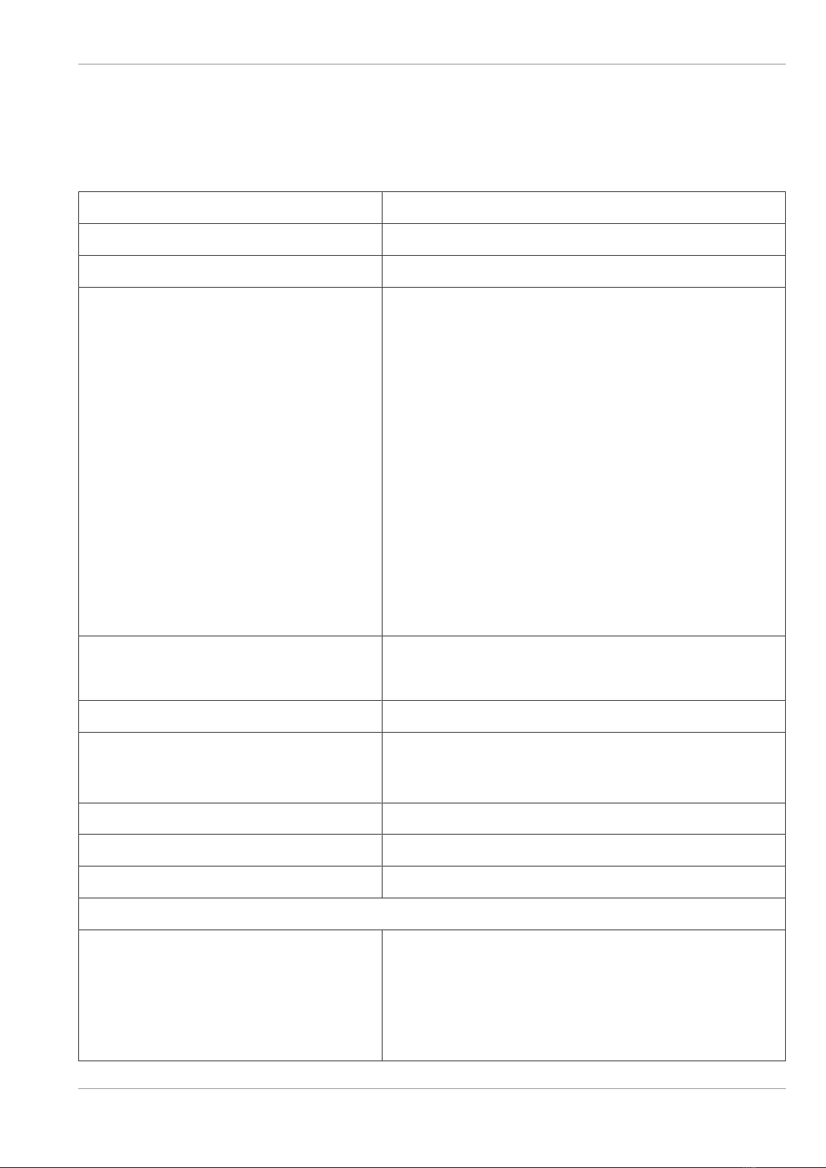
Resolution 203 dpi model: 203 dpi x 203 dpi (8 dots/mm)
Interface (USB Type-B) USB 2.0 High Speed Printer Class
Emulation Mode TH230 and ESP/POS
Character set 437 (US), 720 (Arabic), 737 (Greek), 775 (Baltic), 850
(Multilingual), 852 (Latin II), 857 (Turkish), 858 (with Eu-
rosymbol), 860 (Portuguese), 862 (Hebrew), 863 (French
Canadian), 864 (Arabic), 865 (Nordic), 866 (Cyrillic), 874
(Thai), 1250 (Windows Central Europe), 1251 (Windows
Cyrillic), 1252 (Windows Latin I), 1253 (Windows Greek),
1254 (Windows Turkish), 1255 (Windows Hebrew), 1256
(Windows Arabic), 1257 (Windows Baltic), 28591 (Win-
dows Latin 1), 28592 (Windows Latin 2), 28594 (Windows
Baltic), 28596 (Windows Arabic), 28599 (Windows Turk-
ish), 28605 (Windows Latin 9), Katakana and
KZ_1048(Kazakh)
Asian character set:
932 (Kanji), 949 (Korean), 936 (Simplified Chinese) and
950 (Traditional Chinese with HKSCS extension) and
GB18030
Receipt Printing Speed 203 dpi model: Max. 355 mm/Sec (14 IPS)
Printing speed is varied according to print density.
Character attribute Double width, Double high, rotate, underline, bold
Bar code UPC-A, UPC-E, EAN8, EAN13, Code 39, Code 93, Inter-
leaved 2 of 5, Codabar, Code 128, EAN 128, GS1
Databar, Datamatrix, QR, and PDF-417
Gray scale printing Print Speed 4ips max (101.6 mm/sec), 16 level gray scale
2 color printing Print Speed 5ips max (127 mm/sec)
Line Spacing 7.52 LPI (default)
Resident Font - (It support two font types.)
Character Cell Size**
- Font A*
- Font B
- Kanji
13(H) X 24(V) dots
10(H) X 24(V) dots
24(H) X 24(V) dots
Copyright © 2022, Diebold Nixdorf
01750352498 C
9-1
Specifications
Column Width
- Font A*
- Font B
- Kanji
80 mm Paper mode
44 columns
57 columns
24 columns
58 mm Paper mode
31 columns
40 columns
17 columns
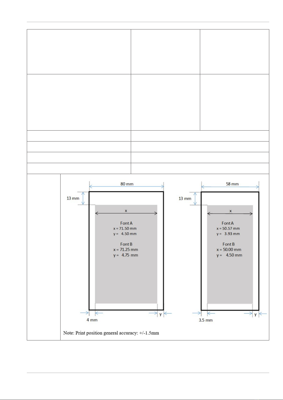
Printable Width 2
- Font A*
- Font B
- Kanji
- Graphics
80 mm Paper mode
572 dots (71.50 mm)
570 dots (71.25 mm)
576 dots (72.00 mm)
576 dots (72.00 mm)
58 mm Paper mode
403 dots (50.37 mm)
400 dots (50.00 mm)
408 dots (51.00 mm)
408 dots (51.00 mm)
Dimension of the printer W 137 mm x H 138.5 mm x D 187 mm
Weight of the printer Approx. 1.3 kg
Dimension including MF module W 137 mm x H 169.5 mm x D 187 mm
Weight including MF module Approx. 2.0 kg
Printable
Area
*MF module supports only font A 80 mm paper mode
** MF module supports big852 font with different character sizes
Copyright © 2022, Diebold Nixdorf
01750352498 C
9-2

Specifications
9.2
9.2 Environmental Usage Conditions
Table9-1: Normal operation
Temperature range 0 - 50°C*
Temperature change Max. 10°C /hour
Humidity range (no condensation) 5% - 90%
Temperature at dew point Max. 26°C
Humidity change Max.10% /hour (at 26°C)
*with MF module 0-40°C
Table9-2: Idle mode
Temperature range 0 - 55°C
Temperature change Max. 10°C /hour
Humidity range (no condensation) 5 - 95%
Temperature at dew point Max. 26°C
Table9-3: Extreme operating range
Temperature range 0 to + 55°C
Temperature change Max. 10°C /hour
Humidity range (no condensation) 10 - 90%
Temperature at dew point Max. 45°C
Table9-4: Storage
Temperature range (Dry Bulb) -10 to + 55°C
Max. Temperature Change 15°C/hour
Humidity range (no condensation) 5% - 90%
Table9-5: Transit
Temperature range (Dry Bulb) -40 to +60°C
Max. Temperature Change 20°C/hour
Humidity range (no condensation) 5% - 95%
Copyright © 2022, Diebold Nixdorf
01750352498 C
9-3
Other manuals for P1200
3
Table of contents
Other DIEBOLD NIXDORF Printer manuals

DIEBOLD NIXDORF
DIEBOLD NIXDORF P1200 User manual

DIEBOLD NIXDORF
DIEBOLD NIXDORF P1300 User manual

DIEBOLD NIXDORF
DIEBOLD NIXDORF P1300 Operating instructions

DIEBOLD NIXDORF
DIEBOLD NIXDORF P1200 User manual

DIEBOLD NIXDORF
DIEBOLD NIXDORF P1200 Owner's manual

DIEBOLD NIXDORF
DIEBOLD NIXDORF TH250 User manual

DIEBOLD NIXDORF
DIEBOLD NIXDORF TH210-VI User manual


