DIEBOLD NIXDORF P1200 User manual

P1200 Standard POS Printer
Thermal Printer
User Manual
01750352498B

Table of Contents
1 MANUFACTURER'S DECLARATION AND APPROVAL .......................................................... 1-1
2 SUPPLIER'S DECLARATION OF CONFORMITY ..................................................................... 2-1
3 SAFETY SUMMARY ................................................................................................................... 3-1
4 IMPORTANT INFORMATION TO THE USER ............................................................................ 4-1
5 UNPACKING ............................................................................................................................... 5-1
6 PRODUCT OVERVIEW............................................................................................................... 6-1
6.1 Introduction ........................................................................................................................6-1
6.2 Features .............................................................................................................................6-1
6.3 Applicable Model................................................................................................................6-2
6.4 Accessories........................................................................................................................6-2
7 SPECIFICATIONS....................................................................................................................... 7-1
7.1 General ..............................................................................................................................7-1
7.2 Environmental usage conditions ........................................................................................7-3
7.3 Internal buffers ...................................................................................................................7-4
7.4 Thermal head basic performance ......................................................................................7-4
7.5 Main Card...........................................................................................................................7-4
7.6 Option Interface Card.........................................................................................................7-5
7.7 Reliability............................................................................................................................7-5
7.8 Options...............................................................................................................................7-6
7.9 Paper Roll ..........................................................................................................................7-7
8 APPEARANCE............................................................................................................................ 8-1
8.1 Front/Rear View .................................................................................................................8-1
8.2 LED and Feed Button.........................................................................................................8-1
8.3 Power Button......................................................................................................................8-2
8.4 Connectors.........................................................................................................................8-3
8.5 Specification of Interface & Power Connector....................................................................8-4
8.5.1 RS232 Interface .................................................................................................. 8-4
8.5.2 Ethernet Interface ............................................................................................... 8-5
8.5.3 Power USB Interface........................................................................................... 8-6
8.5.4 USB Interface...................................................................................................... 8-7
8.5.5 Power Cable Connector...................................................................................... 8-8
8.5.6 Cash Drawer Connector and Pin Assignments................................................... 8-9
9 SET UP PROCEDURE ................................................................................................................ 9-1
9.1 Requirements for Operation...............................................................................................9-1
9.2 Setting up the Printer .........................................................................................................9-3
9.3 Turning off the Printer ........................................................................................................9-4
10 INSTALLATION PROCEDURE................................................................................................... 10-1
10.1 Connecting the Power Cord and Interface Cable...............................................................10-1
10.1.1 Connect to Power Adapter.................................................................................. 10-2
10.1.2 Connect via standard USB Type-B Cable........................................................... 10-2
Copyright © 2021, Diebold Nixdorf
01750352498B
ii

Table of Contents
10.1.3 Connect via Option Card (RS232 & LAN)........................................................... 10-3
10.1.4 Connect via Y-Cable ........................................................................................... 10-4
10.1.5 Connecting via Cash Drawer .............................................................................. 10-5
10.1.6 Interface cable to POS terminal connection position .......................................... 10-5
10.2 Choosing a Location ..........................................................................................................10-6
10.3 Loading the Paper Roll.......................................................................................................10-9
11 DIAGNOSTICS ............................................................................................................................ 11-1
11.1 Offline Diagnostic ...............................................................................................................11-1
12 GENERAL MAINTENANCE........................................................................................................ 12-1
12.1 Cleaning the Covers...........................................................................................................12-1
12.2 Cleaning the Thermal Print Head.......................................................................................12-1
13 TROUBLESHOOTING ................................................................................................................ 13-1
13.1 Removing Jammed Paper..................................................................................................13-1
13.2 Resetting Cutter Failure or Jam .........................................................................................13-2
13.3 Common Problems & Solutions .........................................................................................13-4
13.4 LED Indication Table..........................................................................................................13-7
14 APPENDIX................................................................................................................................... 14-1
14.1 Ethernet..............................................................................................................................14-1
14.2 Web Setting Page ..............................................................................................................14-1
Copyright © 2021, Diebold Nixdorf
01750352498B
iii
1
1 MANUFACTURER'S DECLARATION AND
APPROVAL
WARNING
This is a Class A product. In domestic environment, this product may cause radio interfer-
ence in which user may be required to take adequate measures.
FCC-Class A Declaration
This equipment has been tested and found to comply with the limits for a Class A digital device, pursuant
to part 15 of the FCC Rules. These limits are designed to provide reasonable protection against harmful
interference when the equipment is operated in a commercial environment. This equipment generates,
uses, and can radiate radio frequency energy and, if not installed and used in accordance with the in-
struction manual, may cause harmful interference to radio communications. Operation of this equipment
in a residential area is likely to cause harmful interference in which case the user will be required to cor-
rect the interference at his own expense. Modifications not authorized by the manufacturer may void
users authority to operate this device.
FCC Caution: Any changes or modifications not expressly approved by the party responsible for compli-
ance could void the user's authority to operate this equipment.
This transmitter must not be co-located or operating in conjunction with any other antenna or transmitter.
CAN ICES-3 (A)/NMB-3 (A)
The device complies with the requirements of the EEC directive 2014/30/EU with regard
to ‘Electro-magnetic compatibility" and 2014/35/EU “Low Voltage Directive” and RoHS
directive 2011/65/EU.
Therefore, you will find the CE mark on the device or packaging.
In addition, the P1200 has received the cTUVus symbol.
The following information is for EU-member states only:
Disposal of products
(based on EU-Directive 2012/19/EU)
Directive on Waste electrical and electronic equipment – WEEE)
Copyright © 2021, Diebold Nixdorf
01750352498B
1-1

MANUFACTURER'S DECLARATION AND APPROVAL
The use of the symbol indicates that this product may not be disposed as unsorted munici-
pal waste and has to be collected separately. Integrated batteries and accumulators can be
disposed of with the product. They will be separated at the recycling centers.
The black bar indicates that the product was placed on the market after August 13, 2005.
By ensuring this product is disposed of correctly, you will help prevent potential negative
consequences for the environmental and human health, which could otherwise be caused
by inappropriate waste handling of this product.
For more detailed information about the take-back and recycling of this product, please con-
tact your supplier where you purchased this product.
Changes or modifications not expressly approved by the manufacturer for compliance could void the
User’s authority to operate the equipment.
Copyright © 2021, Diebold Nixdorf
01750352498B
1-2

2
2 SUPPLIER'S DECLARATION OF
CONFORMITY
Product Description: Thermal Printer
Model: P1200
Party issuing Supplier’s Declaration of Conformity
Diebold Nixdorf Singapore PTE. LTD.
30A Kallang Place
#04-01
Singapore 339213
Phone: +65 6747 3828
Responsible Party – U.S. Contact Information
Diebold Nixdorf
5995 Mayfair Road
N. Canton, OH 44720 / USA
Phone: +1 330 490 5049
FCC Compliance Statement (for products subject to Part 15)
This device complies with Part 15 of the FCC Rules. Operation is subject to the following two conditions:
(1) This device may not cause harmful interference, and
(2) this device must accept any interference received, including interference that may cause undesired
operation.
Copyright © 2021, Diebold Nixdorf
01750352498B
2-1

3
3 SAFETY SUMMARY
Personal safety in handling or maintaining the equipment is extremely important. Warnings and Cautions
necessary for safe handling are included in this manual. All warnings and cautions contained in this man-
ual should be read and understood before handling or maintaining the equipment.
Do not attempt to effect repairs or modifications to this equipment. If a fault occurs that cannot be recti-
fied using the procedures described in this manual, turn off the power supply, unplug the machine, and
then contact your authorized Diebold Nixdorf representative for assistance.
Meanings of Each Symbol
This symbol indicates warning items (including cautions).
Specific warning contents are drawn inside the symbol.
(The symbol on the left indicates a general caution.)
This symbol indicates prohibited actions (prohibited items).
Specific prohibited contents are drawn inside or near the symbol.
(The symbol on the left indicates “no disassembling”.)
This symbol indicates actions which must be performed.
Specific instructions are drawn inside or near the ● symbol.
(The symbol on the left indicates “disconnect the power cord plug from the outlet”.)
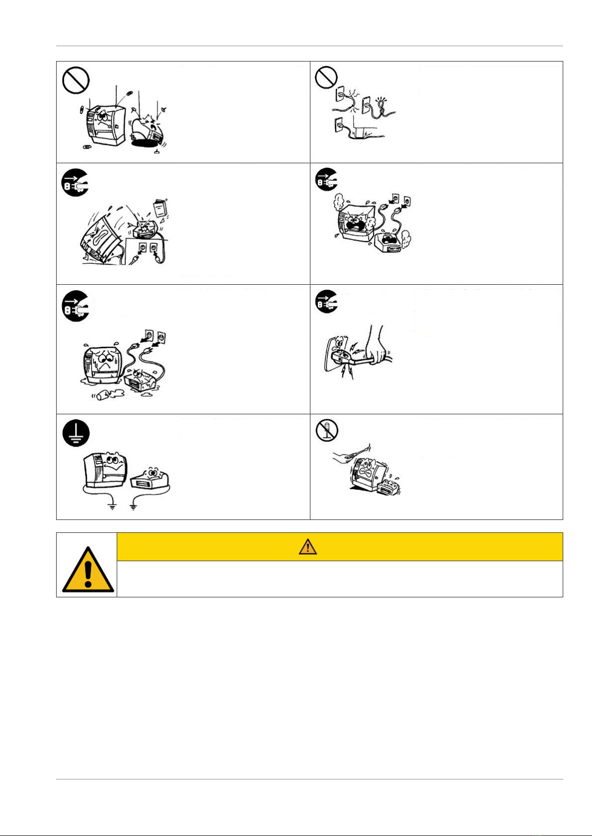
WARNING
This indicates that there is the risk of death or serious injury if the machines are improp-
erly handled contrary to this indication.
Any other than the
specified AC voltage is
prohibited.
Do not use voltages other than the
voltage (AC) specified on the rating
plate, as this may cause fire or
electric shock.
Prohibited Do not plug in or unplug the power cord plug with
wet hands as this may cause electric shock.
If the machines share the same outlet
with any other electrical appliances
which consume large amounts of
power, the voltage will fluctuate widely
each time these appliances operate.
Be sure to provide an exclusive outlet
for the machine as this may cause the
machines to malfunction.
Prohibited
Prohibited Do not place metal objects or water-filled
containers such as flower vases, flower pots or
mugs, etc. on top of the machines. If metal
objects or spilled liquid enter the machines, this
may cause fire or electric shock.
Copyright © 2021, Diebold Nixdorf
01750352498B
3-1
SAFETY SUMMARY
Prohibited Do not insert or drop metal,
flammable or other foreign objects
into the machines through the
ventilation slits, as this may cause fire
or electric shock.
Prohibited Do not scratch, damage or modify the power
cords. Also, do not place heavy objects on, pull
on, or excessively bend the cords, as this may
cause fire or electrical shock.
Disconnect
the plug.
If the machines are dropped or their
cabinets damaged, first turn off the
power switches and disconnect the
power cord plugs from the outlet,
and then contact your authorized
Diebold Nixdorf representative for
assistance. Continued use of the
machine in that condition may cause
fire or electric shock.
Disconnect
the plug.
Continued use of the machines in an abnormal
condition such as when the machines are
producing smoke or strange smells may cause
fire or electric shock. In these cases,
immediately turn off the power switches and
disconnect the power cord plugs from the outlet.
Then, contact your authorized Diebold Nixdorf
representative for assistance.
Disconnect
the plug.
If foreign objects (metal fragments,
water, and liquids) enter the
machines, first turn off the power
switches and disconnect the power
cord plugs from the outlet, and then
contact your authorized Diebold
Nixdorf representative for assistance.
Continued use of the machine in that
condition may cause fire or electric
shock.
Disconnect
the plug. When unplugging the power cords, be sure to hold
and pull on the plug portion. Pulling on the cord
portion may cut or expose the internal wires and
cause fire or electric shock.
Connect a
grounding wire.
Ensure that the equipment is properly
grounded. Extension cables should
also be grounded. Fire or electric
shock could occur on improperly
grounded equipment.
No
disassembling. Do not remove covers, repair or modify the
machine by yourself. You may be injured by high
voltage, very hot parts or sharp edges inside the
machine.
CAUTION
This indicates that there is the risk of personal injury or damage to objects if the machines
are improperly handled contrary to this indication.
Copyright © 2021, Diebold Nixdorf
01750352498B
3-2

SAFETY SUMMARY
Precautions
The following precautions will help to ensure that this machine will continue to function correctly.
• Try to avoid locations that have the following adverse conditions
– Temperatures out of the specification
– Direct sunlight
– High humidity
– Shared power source
– Excessive vibration
– Dust/Gas
• The cover should be cleaned by wiping with a dry cloth or a cloth slightly dampened with a mild de-
tergent solution. NEVER USE THINNER OR ANY OTHER VOLATILE SOLVENT on the plastic cov-
ers.
• USE ONLY DIEBOLD NIXDORF SPECIFIED paper.
• DO NOT STORE the paper where they might be exposed to direct sunlight, high temperatures, high
humidity, dust, or gas.
• Ensure the printer is operated on a level surface or vertical wall..
• Any data stored in the memory of the printer could be lost during a printer fault.
• Try to avoid using this equipment on the same power supply as high voltage equipment or equipment
likely to cause mains interference.
• Unplug the machine whenever you are working inside it or cleaning it.
• Keep your work environment static free.
• Do not place heavy objects on top of the machines, as these items may become unbalanced and fall
causing injury.
• Do not lean against the machine. It may fall on you and could cause injury.
• Care must be taken not to injure yourself with the printer paper cutter.
• Unplug the machine when it is not used for a long period of time.
Copyright © 2021, Diebold Nixdorf
01750352498B
3-3
4
4 IMPORTANT INFORMATION TO THE USER
In order to ensure compliance with the Product Safety, FCC marking requirements, you must use the
power supply, power cord, and interface cable which were shipped with this product or which meet the
following parameters:
Power Adapter
The power adapter is required to comply with the safety and/or EMC requirements depending on the
county where the equipment is used, and to have the following electrical characteristics, Class 1 power
adapter with SELV (Secondary Extra Low Voltage), input rated 100-240 Vac, 2.0A Max, 50/60 Hz, output
rated 24 Vdc, 2.6A.
Interface Cable
You are advised to use a shielded (360 degree) interface cable with this product. The shield must be
connected to the frame or earth ground connection or earth ground reference at BOTH ends of the ca-
ble. If another cable is used than described above you will need to test this cable with the Diebold
Nixdorf printer and your system for local EMC requirements where the equipment is used.
Power Cord
For this product a UL listed, detachable power cord is required. When the power supply is mounted on
the floor, a power cord with Type SJT marking is required. If a power cord is used different from de-
scribed above, you might violate safety certifications which are in force in the country of use. The socket-
outlet needs to be installed near the equipment and must be easily accessible.
Caution Label Information / Informations sur l'étiquette d'avertissement
Hot surface, Do not touch / Surface chaude, Ne pas toucher
Hazardous Moving Parts, Keep Fingers and Other Body Parts Away/ Parties Mobiles Dan-
gereuses Tenir Les Doigts Et Les Autres Parties Du Corps Éloignés.
Power Cord
As the power cord is not supplied with this printer, locally purchase the power cord that meets the follow-
ing standard.
Copyright © 2021, Diebold Nixdorf
01750352498B
4-1

IMPORTANT INFORMATION TO THE USER
For USA and Canada:
Power Cord – UL and CSA approved, type SVT, 18/3AWG, rated min. 125V, 10A
Attached Plug and Appliance Coupler – UL and CSA approved, molded on type.
The plug is parallel-blade grounding type, NEMA 5-15P configuration. The appliance coupler is Female
configuration.
Both attachment plug and appliance coupler are rated minimum 125V, 10A.
For European countries:
Power Supply Cord – HAR or domestic approved where the equipment is used,
Type H05VV-F, rated minimum 250V, 10A.
Attachment Plug and Appliance Coupler – Domestic approved where the equipment is used, molded on
type, having grounding terminal rated minimum 250V, 10A. The appliance coupler is Female configura-
tion.
Copyright © 2021, Diebold Nixdorf
01750352498B
4-2
5
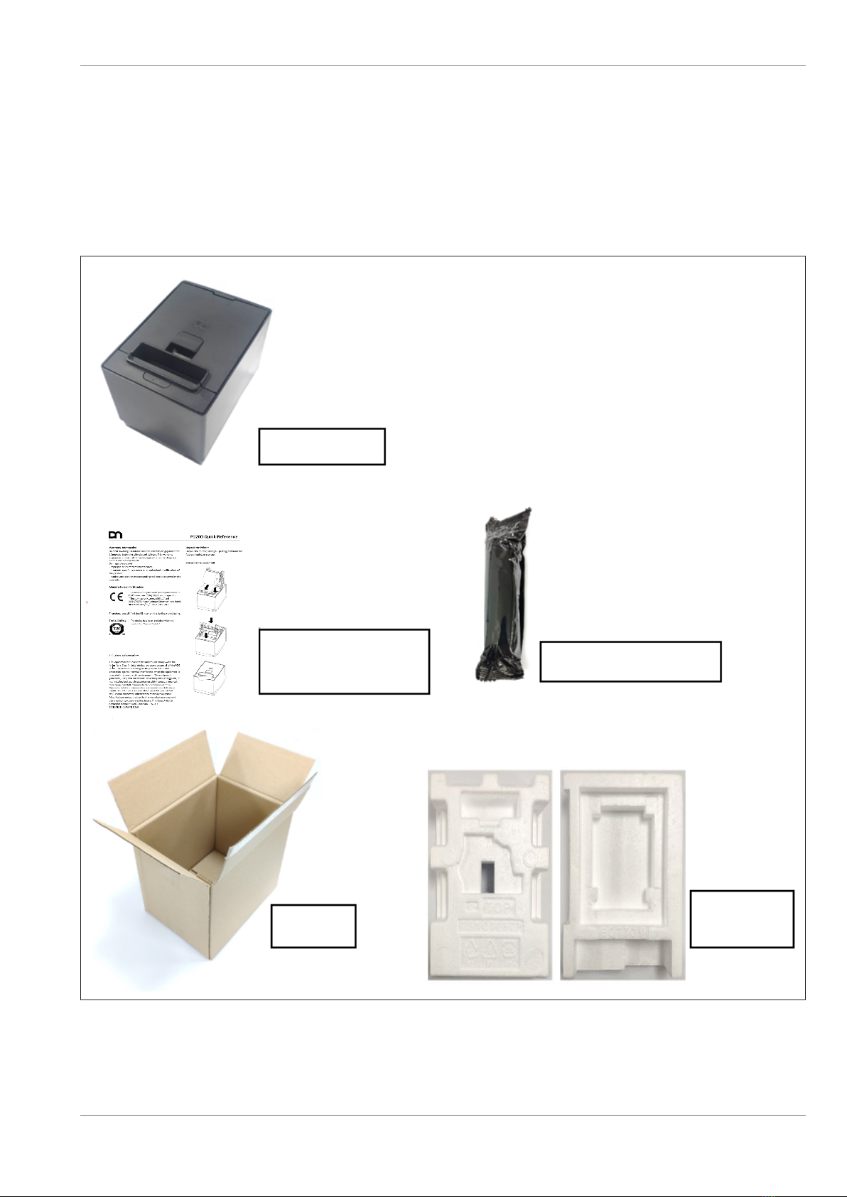
5 UNPACKING
1. Open the carton.
2. Remove the printer from the carton.
3. Check the content and make sure no missing parts.
4. Place the printer on a level surface and make sure no physical damage.
Printer
Quick Installation
Manual Starter Roll
Carton Protector
Pack
Copyright © 2021, Diebold Nixdorf
01750352498B
5-1

UNPACKING
NOTE
Keep the original carton and protector pack for future transportation of the printer.
Copyright © 2021, Diebold Nixdorf
01750352498B
5-2

6
6 PRODUCT OVERVIEW
6.1
6.1 Introduction
This product consists a thermal head for one side printing. Base model includes a 32bit CPU architecture
with Flash ROM, Cash Drawer Connector, Mini-DIN Power, USB Type B connector and expansion con-
nector. The expansion connector is compatible with Power USB I/F, and RS232 I/F or Ethernet I/F as op-
tion.
This manual contains general set-up and maintenance information and should be read carefully to help
gain the maximum performance and life from your printer. For most queries please refer to this manual
and keep it safe for future reference.
6.2
6.2 Features
Drop-in paper loading
Paper out sensor
Paper jam sensor (detecting initial jam of paper at platen roller)
Knife: Cut paper in full cut or partial cut (Partial cut knife leaves 2mm uncut at center).
It supports both detection at horizontal and vertical mount / wall mount orientation.
Copyright © 2021, Diebold Nixdorf
01750352498B
6-1

PRODUCT OVERVIEW
6.3
6.3 Applicable Model
Model name description
Blackmark Option
0001:
0002:
Non-Blackmark sensor
Blackmark sensor
Colour Option
01:
02:
03:
04:
05:
Black
Light Gray
Customer Specific Colour 1
Customer Specific Colour 2
Customer Specific Colour 3
Interface
0001:
0002:
0003:
0004:
USB interface option
RS232 interface option
Ethernet interface option
Power USB interface option
POS Printer (Single/Dual Station)
1200:
1300:
DN Standard POS Printer
DN Hybrid POS Printer
6.4
6.4 Accessories
The following accessories are packed in the shipping carton box as shown below:
1 unit of Printer enclosed in a plastic bag and protector pack
Starter Roll (1pcs)
Quick reference (1 copy)
Copyright © 2021, Diebold Nixdorf
01750352498B
6-2
7
7 SPECIFICATIONS
7.1
7.1 General
Resolution 203 dpi model: 203 dpi x 203 dpi (8 dots/mm)
Interface (USB Type-B) USB 2.0 High Speed Printer Class
Emulation Mode TH230 and ESP/POS
Character set 437 (US), 720 (Arabic), 737 (Greek), 775 (Baltic),
850 (Multilingual), 852 (Latin II), 857 (Turkish),
858 (with Eurosymbol), 860 (Portuguese), 862
(Hebrew), 863 (French Canadian), 864 (Arabic),
865 (Nordic), 866 (Cyrillic), 874 (Thai), 1250
(Windows Central Europe), 1251 (Windows Cyril-
lic), 1252 (Windows Latin I), 1253 (Windows
Greek), 1254 (Windows Turkish), 1255 (Windows
Hebrew), 1256 (Windows Arabic), 1257 (Win-
dows Baltic), 28591 (Windows Latin 1), 28592
(Windows Latin 2), 28594 (Windows Baltic),
28596 (Windows Arabic), 28599 (Windows Turk-
ish), 28605 (Windows Latin 9), Katakana and
KZ_1048(Kazakh)
Asian character set:
932 (Kanji), 949 (Korean), 936 (Simplified Chi-
nese) and 950 (Traditional Chinese with HKSCS
extension) and GB18030
Receipt Printing Speed 203 dpi model: Max. 355 mm/Sec (14 IPS)
Printing speed is varied according to print den-
sity.
Character attribute Double width , Double high ,rotate , under line,
bold
Bar code UPC-A, UPC-E, EAN8, EAN13, Code 39, Code
93, Interleaved 2 of 5, Codabar, Code 128, EAN
128, GS1 Databar, Datamatrix, QR, and PDF-417
Gray scale printing Print Speed 4ips max (101.6 mm/sec), 16 level
gray scale
2 color printing Print Speed 5ips max (127 mm/sec)
Line Spacing 7.52 LPI (default)
Resident Font - (It support two font types.)
Character Cell Size
Copyright © 2021, Diebold Nixdorf
01750352498B
7-1
SPECIFICATIONS
- Font A
- Font B
- Kanji
13(H) X 24(V) dots
10(H) X 24(V) dots
24(H) X 24(V) dots
Column Width
- Font A
- Font B
- Kanji
80mm Paper mode
44 columns
57 columns
24 columns
58mm Paper mode
31 columns
40 columns
17 columns
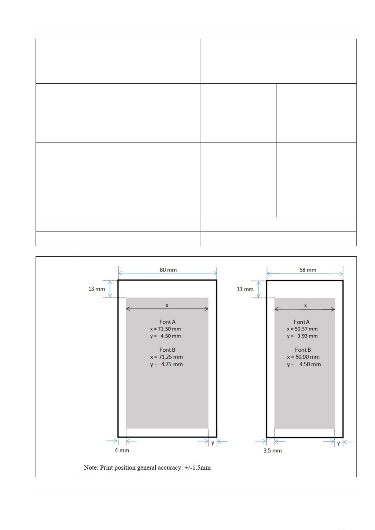
Printable Width 2
- Font A
- Font B
- Kanji
- Graphics
80mm Paper mode
572 dots (71.50 mm)
570 dots (71.25 mm)
576 dots (72.00 mm)
576 dots (72.00 mm)
58mm Paper mode
403 dots (50.37 mm)
400 dots (50.00 mm)
408 dots (51.00 mm)
408 dots (51.00 mm)
Dimension W 137 mm x H 138.5 mm x D 187 mm
Weight Approx. 1.3 Kg
Printable
Area
Copyright © 2021, Diebold Nixdorf
01750352498B
7-2

SPECIFICATIONS
7.2
7.2 Environmental usage conditions
1) During normal operation
Temperature range : 0 - 50°C
Temperature change : Max. 10°C /hour
Humidity range (no condensation) : 5% - 90%
Temperature at dew point : Max. 26°C
Humidity change : Max.10% /hour (at 26°C)
2) In idle mode
Temperature range : 0 - 55°C
Temperature change : Max. 10°C /hour
Humidity range (no condensation) : 5 - 95%
Temperature at dew point : Max. 26°C
3) Extreme operating range
Temperature range : 0 - 55°C
Temperature change : Max. 10°C /hour
Humidity range (no condensation) : 10 - 90%
Temperature at dew point : Max. 45°C
4) Storage
Temperature range (Dry Bulb) : -10 - 55°C
Max. Temperature Change : 15°C/hour
Humidity range (no condensation) : 5% - 90%
5) Transit
Temperature range (Dry Bulb) : -40 - 60°C
Max. Temperature Change : 20°C/hour
Humidity range (no condensation) : 5% - 95%
Copyright © 2021, Diebold Nixdorf
01750352498B
7-3

SPECIFICATIONS
7.3
7.3 Internal buffers
RAM (Total Size: IRAM 1.25MB, DRAM 8MB)
Interface Receive Data buffer 64 KB
Interface Send Data buffer 1 KB
User-defined Logo buffer 256 KB
Macro buffer 2 KB
Flash Memory (Total Size: 8MB)
User-defined Logo area 256 KB
User-defined Character area 64 KB
User-defined Data area 64 KB
Macro area 2 KB
7.4
7.4 Thermal head basic performance
1) Type : Line thermal
2) Number of heating elements : 640 dots
3) Dot density : 8 dots/mm
4) Effective recording width : 80.00 mm
5) Data transmission method : 2 serial I/O inputs.
6) Number of strobes : 2
7.5
7.5 Main Card
1) CPU : SH7267 (SH2A)
2) Operation Clock (CPU Internal) : 144 MHz
3) Program ROM : 64M bits Serial Flash ROM
(W25Q64JVSSIQ/TRAY or equivalent)
4) RAM : 64M bits SDRAM
(W9864G6KH-6 or equivalent)
5) I/F circuit : USB I/F (Type B)
6) Other I/F Connector : Cash Drawer Connector
7) Input : DC 24V Input
8) Indicator and SW : LED (Green, Red and Amber), Feed Button &
Power Button
Copyright © 2021, Diebold Nixdorf
01750352498B
7-4

SPECIFICATIONS
7.6
7.6 Option Interface Card
1) Option Interface board 1 : Serial RS232 I/F
2) Option Interface board 2 : Ethernet 10Base-t, 100Base-TX I/F
3) Option Interface board 3 : Power USB
* Only one optional interface card is available to integrate into the printer.
7.7
7.7 Reliability
2.7.1 Life
Thermal print head : 200 km (based on specified paper NPI TF50KS-EY)
Cutter : 3 million cuts (based on specified paper NPI TF50KS-EY)
2.7.2 Life MTBF (MCBF)
Printer : 70,000,000 Lines at 7.52lines/inch(MCBF)
MAIN PCB : 1,650,000 hours (Telcordia RPP, formerly Bellcore)
Interface PCB, RS232 I/F : 43,450,000 hours (Telcordia RPP, formerly Bellcore)
Interface PCB, Ethernet I/F : 26,300,000 hours (Telcordia RPP, formerly Bellcore)
Interface PCB, Power USB : XXXXXX hours (Telcordia RPP, formerly Bellcore)
Condition:
Above MTBF and MCBF has been confirmed under Normal environment (at 25ºC)
The default line spacing is 7.52LPI.
Copyright © 2021, Diebold Nixdorf
01750352498B
7-5
Other manuals for P1200
3
Table of contents
Other DIEBOLD NIXDORF Printer manuals

DIEBOLD NIXDORF
DIEBOLD NIXDORF P1200 User manual

DIEBOLD NIXDORF
DIEBOLD NIXDORF P1300 User manual

DIEBOLD NIXDORF
DIEBOLD NIXDORF P1300 Operating instructions

DIEBOLD NIXDORF
DIEBOLD NIXDORF P1200 User manual

DIEBOLD NIXDORF
DIEBOLD NIXDORF P1200 Owner's manual

DIEBOLD NIXDORF
DIEBOLD NIXDORF TH250 User manual

DIEBOLD NIXDORF
DIEBOLD NIXDORF TH210-VI User manual


