DIEBOLD HS 1100-P User manual

Bedienungsanleitung
User Manual
BA_79-329_0_D+E.docx
Copyright © Diebold 2017-04 Ersteller: kh
Seite 1 von 60
Horizontal-Schrumpfgerät
Horizontal Shrinking Device
HS 1100-P
Helmut Diebold GmbH & Co.
An der Sägmühle 4
D-72417 Jungingen (Germany)
Tel.: + 49 (0)7477-871-0 Fax: + 49 (0)7477-871-30

Horizontal-Schrumpfgerät
Horizontal Shrinking Device
HS 1100-P
BA_79-329_0_D+E.docx
Copyright © Diebold 2017-04 Ersteller: kh
Seite 2 von 60
Information zum Hersteller / Manufacturer
Helmut Diebold GmbH & Co.
Goldring Werkzeugfabrik
An der Sägmühle 4
D-72417 Jungingen (Germany)
Tel.: + 49 (0) 74 77-871-0
Fax: + 49 (0) 74 77-871-30
Web: www.diebold-hsk.de
Mail: [email protected]
Copyright
Copyright © 2017 Helmut Diebold GmbH & Co. Goldring Werkzeugfabrik.
Alle Rechte vorbehalten.
Weitergabe sowie Vervielfältigung und Nutzung dieser Unterlage ist nur mit
Genehmigung der Helmut Diebold GmbH & Co. Goldring Werkzeugfabrik gestattet.
Änderung
Die Firma Helmut Diebold GmbH & Co. behält sich inhaltliche und technische
Änderungen vor.
Gewährleistung
Für Schäden, die durch Nichtbeachtung dieser Anleitung entstehen, wird keine Haftung
übernommen.
Copyright
Copyright © 2017 Helmut Diebold GmbH & Co. Goldring Werkzeugfabrik.
All Rights reserved.
This manual is property of Helmut Diebold GmbH & Co. Goldring Werkzeugfabrik and
may not be copied without the approval of Diebold.
Changes
Helmut Diebold GmbH & Co. reserves the right to modify the specifications of this
device to reflect technical advances.
Warranty
All Diebold devices are warranted to be free from manufacturing and / or material
defect. Misuse of the devices will void warranty.

Horizontal-Schrumpfgerät
Horizontal Shrinking Device
HS 1100-P
BA_79-329_0_D+E.docx
Copyright © Diebold 2017-04 Ersteller: kh
Seite 5 von 60
English..................................................................................................................... 33
14. Foreword........................................................................................................... 33
14.1. Outline ........................................................................................................ 33
14.2. Note............................................................................................................ 33
15. Symbols and pictograms ................................................................................... 34
16. General Safety instructions ............................................................................... 35
16.1. Operating location ...................................................................................... 35
16.2. Hazards from electric components ............................................................. 36
16.3. Hazards from hot parts ............................................................................... 36
16.4. Avoid overheating “ThermoGrip” Chucks.................................................... 37
16.5. Hazards from electromagnetic radiation..................................................... 37
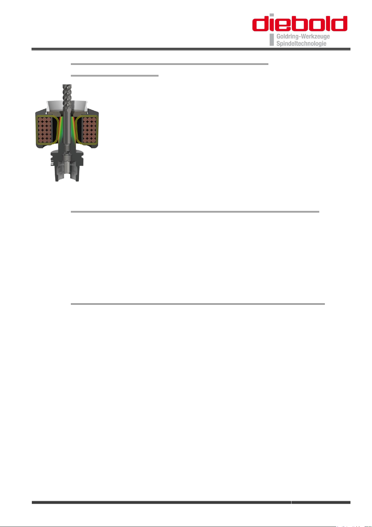
17. General information about ThermoGrip ® Shrink technology............................. 38
17.1. Micro processor controlled Induction generator HS 1100-P........................ 38
17.2. Advantages of ThermoGrip ® Shrink technology at a glance:...................... 38
17.3. Quality of the tools and chucks ................................................................... 39
17.3.1. Tool shanks .......................................................................................... 39
17.3.2. Shrink fit chuck holes ........................................................................... 39
18. Initial Set-Up of the HS 1100-P........................................................................... 40
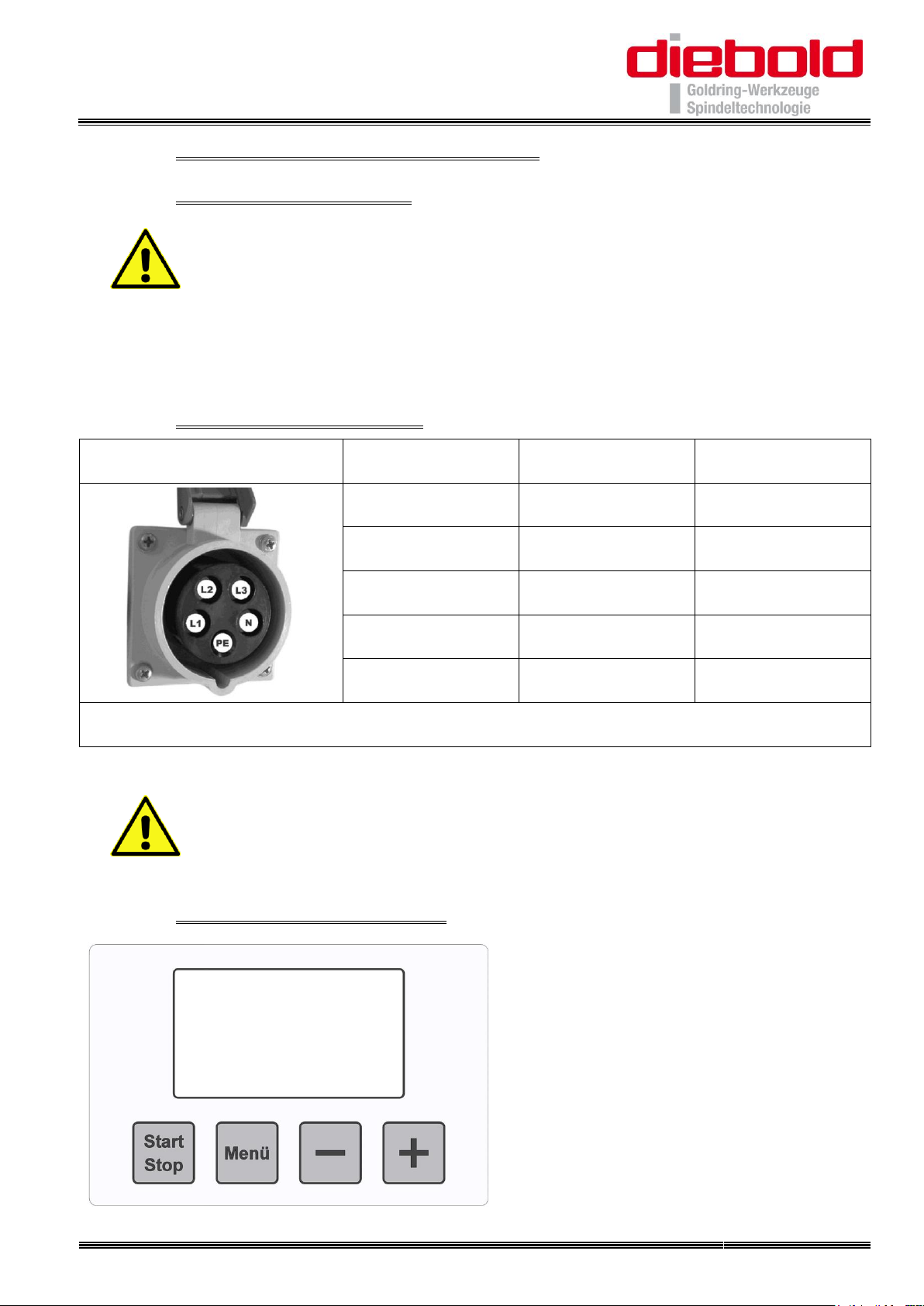
18.1. Connecting the device ................................................................................ 40
18.2. On-site socket and fuse............................................................................... 40
18.3. Controls of the HS 1100-P ........................................................................... 40
19. Operating the HS 1100-P ................................................................................... 41
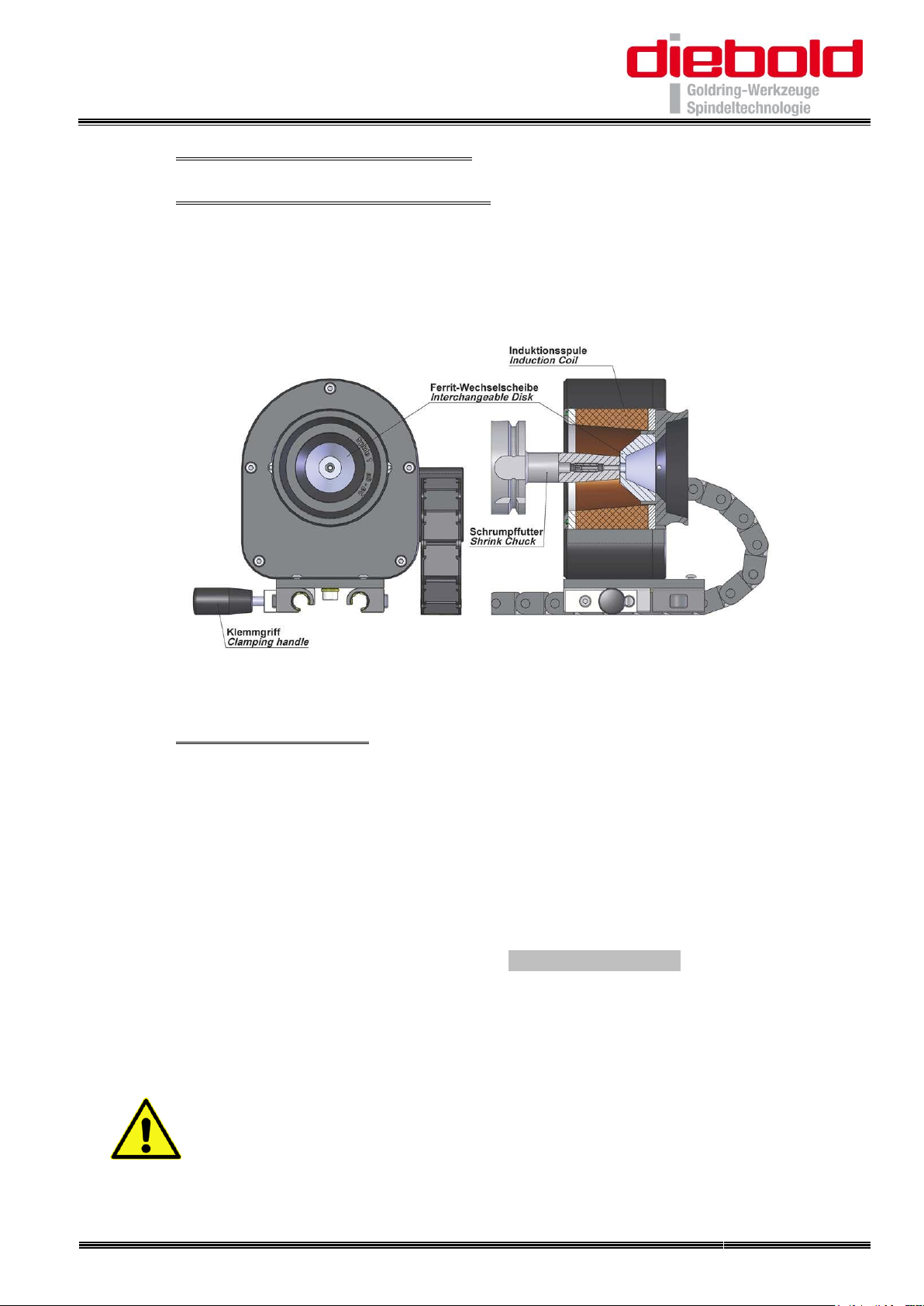
19.1. Ferrite Interchangeable Discs..................................................................... 41
19.2. Shrinking Process....................................................................................... 41
19.3. LCD-Messages............................................................................................ 42
19.4. Shrinking with Parameters.......................................................................... 43
19.5. Shrinking without Parameters with indicating the power level .................... 44
19.6. Changing Standard Parameters.................................................................. 45
19.7. Reset to Factory Settings............................................................................ 46
20. Handling tool holders ........................................................................................ 47
20.1. Tool holder HSK-40 to HSK-100 .................................................................. 47
20.2. Tool holder SK / BT 30 to SK / BT 50 ............................................................ 48
20.3. Universal Adaptor for Clamping range Ø12 to Ø100 ................................... 48
21. Operation of the Length Setting Unit (Optional) ................................................. 49
21.1. Assembly .................................................................................................... 49
21.2. Measuring................................................................................................... 49
21.3. Shrink on length.......................................................................................... 49

Horizontal-Schrumpfgerät
Horizontal Shrinking Device
HS 1100-P
BA_79-329_0_D+E.docx
Copyright © Diebold 2017-04 Ersteller: kh
Seite 6 von 60
22. Appendix ........................................................................................................... 50
22.1. Technical data ............................................................................................ 50
22.2. Block diagram............................................................................................. 50
22.3. Wiring diagram ........................................................................................... 51
22.4. Scope of delivery and accessories.............................................................. 52
22.5. Expansion options and optional accessories............................................... 52
22.5.1. Tool Adaptor......................................................................................... 52
22.5.2. Length Setting Unit............................................................................... 53
22.5.3. Chiller Unit ........................................................................................... 53
23. Cleaning and maintenance ................................................................................ 54
24. Service and repair / Contact the Manufacturer .................................................. 54
24.1. Repair process ........................................................................................... 54
25. EC Declaration of Conformity ............................................................................ 55
26. 5 Finger-Safety-Glove........................................................................................ 56
26.1. Instructions for use ..................................................................................... 56
26.2. EC Declaration of Product Conformity ........................................................ 57

Horizontal-Schrumpfgerät
Horizontal Shrinking Device
HS 1100-P
BA_79-329_0_D+E.docx
Copyright © Diebold 2017-04 Ersteller: kh
Seite 33 von 60
English
14. Foreword
This user manual is part of the technical documentation for the Horizontal Shrinking
Device HS 1100-P manufactured by Helmut Diebold GmbH & Co..
This user manual contains all information necessary for proper use of the unit.
The contents correspond to the stage of construction of the Horizontal Shrinking
Device HS 1100-P at the time of preparation of this manual. Due to continuous
development and customization, design and specifications are subject to change.
Data, diagrams, drawings, descriptions, and etc. included in this manual are for
informational purposes only, and are not to be used for manufacture.
The intent of this operation is to familiarize you with the Horizontal Shrinking DeviceHS
1100-P and facilitate its proper use.
Please inform us if you should find any errors in this manual.
All Diebold products are manufactured according to the current standards for quality
products. We recommend to service the units periodically as recommended in this
manual. The manual contains all data to enable the user to use the units according to
the manufacturers recommendations.
14.1. Outline
This user manual contains important instructions for the safe operation of the
Horizontal Shrinking DeviceHS 1100-P, for reducing repair costs and downtime, and for
increasing the reliability and service life of the induction unit.
The foot line shows the name of the unit on the left, the date of compilation in the middle
and the page number on the right.
14.2. Note
Please store the original packaging of the Horizontal Shrinking Device HS 1100-P in
case the unit needs to be returned to Diebold for service or maintenance.

Horizontal-Schrumpfgerät
Horizontal Shrinking Device
HS 1100-P
BA_79-329_0_D+E.docx
Copyright © Diebold 2017-04 Ersteller: kh
Seite 34 von 60
15. Symbols and pictograms
Warnings: Are marked by warning triangles with a hazard symbol, and warn of
dangers resulting in personal injury or damage to property.
General warning
Hazard posed by electric current or voltage
Commands: Are marked by circles with hazard symbol or square with instructions,
and describe an activity or the use of certain items or objects.
Wear goggles
Wear safety gloves
Notes: Are marked by the information pictogram and contain recommendations
or other additional information.
Example:
Detailed instructions for the chemical test method are available from
your supplier.
Lists: Are marked by the symbol
Example:
Can be used for high speeds
Highest clamping forces
Slim body chuck
Activities: Are marked by the symbol and provide instructions for the stated
activity. The result of the activity can be stated as explanation.
Example:
Change coil
Set shrinking time
Remove tool

Horizontal-Schrumpfgerät
Horizontal Shrinking Device
HS 1100-P
BA_79-329_0_D+E.docx
Copyright © Diebold 2017-04 Ersteller: kh
Seite 35 von 60
16. General Safety instructions
For shrink fit chucks a new technique is used, which allows the tool change with the
matching shrink chuck in a convenient, efficient and energy saving method. The
induction generator is built using state of the art technology at the time of delivery and
is reliable. Nevertheless, the equipment may pose a hazard if it is not used by trained or
at least instructed personnel and / or for the intended use. Therefore, please note:
Read the operating manual carefully before initial set-up and operation
of the unit, and become well acquainted with the control elements.
The operating manual is an integral part of the unit, and must be
accessible and understood by all persons working with the unit.
Only trained individuals should be allowed to operate this unit.
The unit may only be operated as specified for and under good working
conditions.
This unit is designed and programmed for the use of Diebold “ThermoGrip” chucks.
When other shrink chuck forms and designs are used, problems may occur, because
shrink parameters are set for Diebold shrink chuck contours.
Only use Diebold shrink fit chucks! For other shrink fit chucks no
warranty can be given.
Unauthorized modifications or repairs to the unit will void warranty. Such modifications
lead to damage of the unit.
16.1. Operating location
The Horizontal Shrinking Device HS 1100-P is a table-top unit.
Place the unit on a clean, dry workbench, in a dust and vibration-free
environment.
Avoid direct sunlight on LCD display.

Horizontal-Schrumpfgerät
Horizontal Shrinking Device
HS 1100-P
BA_79-329_0_D+E.docx
Copyright © Diebold 2017-04 Ersteller: kh
Seite 36 von 60
16.2. Hazards from electric components
The unit contains components with dangerous voltages. Please observe the following
for your own safety:
This unit is to be serviced ONLY by trained personal authorized by the
manufacturer.
Do not allow metal chips or liquids to enter the unit.
Unit should be cleaned regularly.
Only ThermoGrip chucks and quality cutting tools should be used.
16.3. Hazards from hot parts
The very effective form of heating only heats the relevant boundary zones of the shrink
fit chuck with low heat input.
The surface of the shrink fit chuck can heat up to approx. 400°C.
Caution! Risk of burns!
For your own safety, comply with the following safety rules when working with the unit:
Ensure that hot parts cannot be touched by mistake.
Never leave hot “ThermoGrip” chucks uncovered. Remove hot tools
from the coil and place them in their respective cooling positions or in
the Chiller Unit.
Do not place hot tools on flammable surfaces.
When shrinking tools in and out, always wear the supplied gloves for
protection from burns and cuts.
Remove all metallic objects from the environment of the inductive coil!.
During operation, remove all jewelry and keep hands clear of coil.

Horizontal-Schrumpfgerät
Horizontal Shrinking Device
HS 1100-P
BA_79-329_0_D+E.docx
Copyright © Diebold 2017-04 Ersteller: kh
Seite 37 von 60
16.4. Avoid overheating “ThermoGrip”Chucks
The chuck and tool can overheat as a result of incorrectly entered shrink parameters
and repeated heating of a “ThermoGrip” chuck in a short period of time. This is why the
shrink parameters must be entered with particular care. Use a lower setting if in doubt.
Repeated heating the chuck is to be avoided. Before heating chucks again, make sure
to cool it down to room temperature first.
Avoid the use of excessive shrinking energy and long shrink times.
Do not keep flammable substances in the vicinity of the unit.
Do not use flammable cleaning agents.
16.5. Hazards from electromagnetic radiation
When the unit is used properly, there is no magnetic radiation to the immediate
surroundings. The radiation safety of the unit has been tested and verified by
EN 55011:2007+A2:2007 category A group 2. If the Inductive heating is started up
without a tool holder in the coil, the magnetic field affects only the immediate vicinity of
the coil.
For your own safety, please comply with the following rules:
Do not run any other units into the vicinity of the unit to avoid electrical
interference.
If you have a cardiac pacemaker, please consult the manufacturer or
your doctor. In certain cases, interference is possible.

Horizontal-Schrumpfgerät
Horizontal Shrinking Device
HS 1100-P
BA_79-329_0_D+E.docx
Copyright © Diebold 2017-04 Ersteller: kh
Seite 38 von 60
17. General information about ThermoGrip ®
Shrink technology
Shrinking has been known as a technique for achieving non-
detachable connections, and offers remarkable advantages for
chucking tools. By the inductive heating with high energy density,
tools can be changed in a matter of seconds.
A cylindrical tool is pushed into a heated and expanded bore of the
chuck; after the chuck has cooled, a high radial clamping force is
applied. When handled properly, the clamping operation is
reversible and can be repeated as often as required. The possible
clamping forces are higher than any conventional clamping
techniques.
Only shrink using clean tools in cleaned chucks!
17.1. Micro processor controlled Induction generator HS 1100-P
With the help of special coils, only the specific clamping area of the chuck is heated.
This means it is possible to shrink out carbide tools as well as tools with the same
temperature expansion behavior as the tool holder (e.g. HSS tools).
A special housing / shield surrounding the coil prevents magnetic flux to a large extent.
The control components and the high frequency generator are integrated in the
housing.
17.2. Advantages of ThermoGrip ® Shrink technology at a glance:
Quick shrinking times in and out
High clamping forces
Higher tool and spindle life due to small run-out (< 3 µm)
Good surface finish due to high rigidity of the tool clamping system
High flexural yield strength and radial clamping strength and stability also with
long body lengths
Slim body of the chucks for high speeds
Only localized yet homogeneous heating of the chuck
Clamping of carbide and HSS tools (see 4.3.1 Werkzeugschäfte)
Fastest possible cooling time of the tool and chuck
Specific heat-resistant steel give the chucks a high tool life and makes them
dimensionally stable

Horizontal-Schrumpfgerät
Horizontal Shrinking Device
HS 1100-P
BA_79-329_0_D+E.docx
Copyright © Diebold 2017-04 Ersteller: kh
Seite 39 von 60
17.3. Quality of the tools and chucks
Tool shafts and shrink fit chucks must have the following characteristics to guarantee a
easy on- or unshrinking process.
17.3.1. Tool shanks
must be smooth
must be free of oil and grease
preferably should not have a clamping face
must not have any marking with raised areas
must have the necessary tolerance quality
The following shank tolerances are required for the various shank diameters:
Shank-Ø
Shank tolerance
Tool type
3 mm
h4
Carbide
4 mm
h4
Carbide
5 mm
h5
Carbide
≥ 6 mm
h6
Carbide or HSS
17.3.2. Shrink fit chuck holes
must be smooth
must be free of oil and grease
must have the necessary quality of tolerance

Horizontal-Schrumpfgerät
Horizontal Shrinking Device
HS 1100-P
BA_79-329_0_D+E.docx
Copyright © Diebold 2017-04 Ersteller: kh
Seite 40 von 60
18. Initial Set-Up of the HS 1100-P
18.1. Connecting the device
To ensure that the unit is not damaged during the unpacking process,
unload the unit with the top facing up. Do not hold the unit housing by
the coil.
Connect the power cord to the power supply. Make sure that the main power switch
while the unit is off. Through the operation of the main switch, the device is now ready
for operation. The LC display will show "Diebold".
18.2. On-site socket and fuse
Picture
Pin designation
Pin name
Wire colour
L1
Phase L1
brown
L2
Phase L2
black
L3
Phase L3
black / grey
N
Neutral wire
blue
PE
Protective earth
green-yellow
The rated voltage between the phases is 3x400V (-10/+10%)
Always connect the neutral wire N and protective earth PE !
If a ground fault circuit-breaker is used to secure the CEE socket, it
must be a 4-pin model and according to DIN VDE 0100 (part 530) for
frequency converters of type B (all-current-sensitive).
18.3. Controls of the HS 1100-P

Horizontal-Schrumpfgerät
Horizontal Shrinking Device
HS 1100-P
BA_79-329_0_D+E.docx
Copyright © Diebold 2017-04 Ersteller: kh
Seite 41 von 60
19. Operating the HS 1100-P
19.1. Ferrite Interchangeable Discs
Ferrite interchangeable discs are used for the effective heat shrinking process and are
necessary for shrinking of Carbide and HSS tools. The discs will concentrate the
magnetic field in a way so the tool holder will open up faster. The interchangeable discs
are inserted in the RH side of the coil and locked in place with a clockwise turning
motion. They will serve as a limiter for the toolholder.
A complete set of interchangeable discs comes with the unit.
19.2. Shrinking Process
The shrinking and un-shrinking of a tool works as:
Clamp the shrink chuck in the tool adaptor
Move the induction coil to the required shrink position and lock it by turning the
lock handle
Select shrinking parameters (see 19.4)
Start the heating process by pressing the “Start/Stop” button. When the heating
cycle is completed, push the tool in or pull out the tool.
The induction coil may now be pushed back and the (hot) shrink fit chuck may be
removed for cool down.
Always use the gloves supplied with the unit.
ATTENTION! To prevent damage to the device, the induction coil
should never be moved relative to the chuck during the shrinking
process.

Horizontal-Schrumpfgerät
Horizontal Shrinking Device
HS 1100-P
BA_79-329_0_D+E.docx
Copyright © Diebold 2017-04 Ersteller: kh
Seite 42 von 60
19.3. LCD-Messages
After switching on the device the
Software version (in picture "v02.1")
and the
Number of shrink cycles (in picture "82")
will be displayed for approx. 3 seconds.
The following messages may appear in the LC display:
ATTENTION! Heating time too long !!
the maximum permissible heating time has been exceeded. Heating of the shrink
chuck will automatically be stopped
•Max. temp. coil, please wait -
the maximum permissible coil temperature has been exceeded. Please wait a few
minutes until the inductor has cooled down
•Max. temp. IGBT, please wait -
the maximum permissible IGBT temperature (transistors in the generator) has
been exceeded. Please wait a few minutes until the IGBTs have cooled down
Fault !! -
a fault has occurred
Overload -
the generator is overloaded
IGBT Error -
an IGBT error has occurred
If error messages continue even after switching the unit off and back on, please contact
the manufacturer.
(Observe the cool down of the generator!)

Horizontal-Schrumpfgerät
Horizontal Shrinking Device
HS 1100-P
BA_79-329_0_D+E.docx
Copyright © Diebold 2017-04 Ersteller: kh
Seite 43 von 60
19.4. Shrinking with Parameters
21. Turn on the unit with the main switch
22. Select the shrink chuck type using the ”Menü“ button
Menu and the shrink chuck types will appear:
Manual: Shrinking without parameters
Standard: DIN holder contour (without grooves)
II TSF: Slim holders (2 grooves)
(To shrink Carbide tools only, not HSS shanks!)
IIII Pyroquart: Holders with Pyroquart contour (4 grooves)
TER 11 to 32: Shrink Collet TER / ER 11 to ER 32
23. Select the tool shank-Ø with the „+“ or „–“ button
24. Insert the correct ferrite interchangeable disc in the coil
Disc selection:
Ø3-5
Ø6-12
Ø14-22
Ø25-32
25. Set the induction coil in the position over the heat shrink tool so that the shrink
chuck is in contact with the ferrite interchangeable disc
26. Start the shrinking process with the “Start/Stop“ button
27. At the end of the shrink cycle, shrink or un-shrink the tool

Horizontal-Schrumpfgerät
Horizontal Shrinking Device
HS 1100-P
BA_79-329_0_D+E.docx
Copyright © Diebold 2017-04 Ersteller: kh
Seite 44 von 60
19.5. Shrinking without Parameters with indicating the power level
28. Turn on the unit with the main switch
29. Press the “Menü“ button until “Manuell“ is shown in the display
30. Select the Power level with the “+“ or “–“ button
Power level:
30%
40%
50%
75%
100%
Full power (100%):
When shrinking HSS tools, full power must be applied, otherwise
releasing of the tool will not work. Most carbide tools may also be
heated at full power.
Reduced power (30% - 75%):
When shrinking carbide tools in holders with thin nose type or slim
chucks (especially shrink extensions), it is recommended to heat
with reduced power to avoid overheating of the shrink chuck
Shrink chucks with D1<17 mm should always be heated with
reduced power
If it is not possible to shrink a carbide tool using reduced power,
then the shrink process with full power may be used
31. Insert the correct ferrite interchangeable disc
Disc selection:
Ø3-5
Ø6-12
Ø14-22
Ø25-32
32. Set the induction coil in the position over the heat shrink tool so that the shrink
chuck is in contact with the ferrite interchangeable disc
33. Press and hold the “Start/Stop“ button until shrink or un-shrinking the tool

Horizontal-Schrumpfgerät
Horizontal Shrinking Device
HS 1100-P
BA_79-329_0_D+E.docx
Copyright © Diebold 2017-04 Ersteller: kh
Seite 45 von 60
19.6. Changing Standard Parameters
34. Turn on the unit with the main switch
35. Select the shrink chuck type with the ”Menü“ button
Menu and the shrink chuck type will appear:
Manual: Shrinking without parameters
Standard: DIN holder contour (without grooves)
II TSF: Slim holders (2 grooves)
IIII Pyroquart: Holders with Pyroquart contour (4 grooves)
TER 11 to 32: Shrink Collet TER / ER 11 to ER 32
36. Select the tool shank-Ø with the ”+“ or ”–“ button
37. Press the ”+“ and ”–“ button simultaneously
38. The power level flashes in the display when you release the buttons:
Select the required power level with the ”+“ and ”–“ button and confirm by pressing
the ”Menü“ button
39. The time flashes in the display:
Select the required time with the ”+“ and ”–“ button and confirm by pressing the
”Menü“ button
40. Parameter is successfully stored
ATTENTION!
The shrink fit chucks can be damaged by overheating through
changing the default parameters.

Horizontal-Schrumpfgerät
Horizontal Shrinking Device
HS 1100-P
BA_79-329_0_D+E.docx
Copyright © Diebold 2017-04 Ersteller: kh
Seite 46 von 60
19.7. Reset to Factory Settings
41. Turn on the unit with the main switch
42. Hold down the ”+“ and ”–“ button simultaneously and press the ”Menü“ button
43. When releasing the ”+“ and ”–“ button the display shows:
44. Confirm by pressing the “Start/Stop“ button
when released, the display shows:
45. Confirm by pressing the ”Menü“ button
when released, the display shows:
46. Turning off and turning back on the unit with the main switch
47. The factory settings are being restored

Horizontal-Schrumpfgerät
Horizontal Shrinking Device
HS 1100-P
BA_79-329_0_D+E.docx
Copyright © Diebold 2017-04 Ersteller: kh
Seite 47 von 60
20. Handling tool holders
The different tool holders are inserted up to the stop on the receiving rail and secured
with the clamping screw against displacement.
The tool holders for HSK and SK / BT have a Ejector pin to push the cutting tools during
unshrinking from the clamping bore.
Clamping the Ejector pin with the clamping bolt for Ejector pin you will get a length stop
of the tools while shrinking.
20.1. Tool holder HSK-40 to HSK-100
Shrink fit chucks with HSK taper are inserted into the tool holder and the clamp handle
is swung down. By this means the shrink fit chuck is clamped by an internal cam.

Horizontal-Schrumpfgerät
Horizontal Shrinking Device
HS 1100-P
BA_79-329_0_D+E.docx
Copyright © Diebold 2017-04 Ersteller: kh
Seite 48 von 60
20.2. Tool holder SK / BT 30 to SK / BT 50
The shrink fit chuck is inserted into the tool holder and the lock nut is turned clockwise
while the shrink fit chuck is clamped in the gripper groove or flange. By adjusting the
clamping nut SK or BT shrink fit chucks can be tightened.
20.3. Universal Adaptor for Clamping range Ø12 to Ø100
The shrink fit chucks are clamped in the universal Adaptor by adjusting the jaws with
the control handle. In the jaws there are different entry and contact surfaces available
to clamp diameters of Ø12 to Ø100.
Table of contents
Other DIEBOLD Industrial Equipment manuals
Popular Industrial Equipment manuals by other brands

DuctSox
DuctSox SkeleCore Pull-Tight Cable installation manual

Entes
Entes GEMO Quick start manual

Littelfuse
Littelfuse Industrial Shock Block SB5000 Series manual

Siemens
Siemens SIRIUS 3RA243-8X.32-1 Series Original operating instructions

Morgana
Morgana AutoCreaser Pro 33 Service manual

Desoutter
Desoutter Industrial Tools SD Series Servicing and operating instructions

VS
VS DATAGONE LG-PLUS operating manual

Abicor Binzel
Abicor Binzel CAT3 PRO Operating instruction

TE Connectivity
TE Connectivity Raychem EPP-0001-INT-1/12 Installation instruction

PCB
PCB M1631-04C Installation and operating manual

schmersal
schmersal AZM 415-33 operating instructions

Promac
Promac JMDT-804516-DRO manual