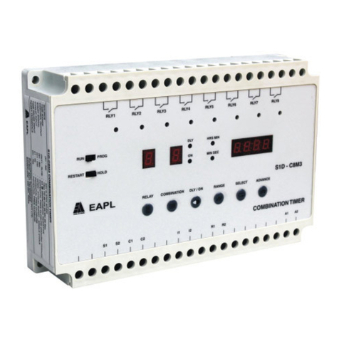
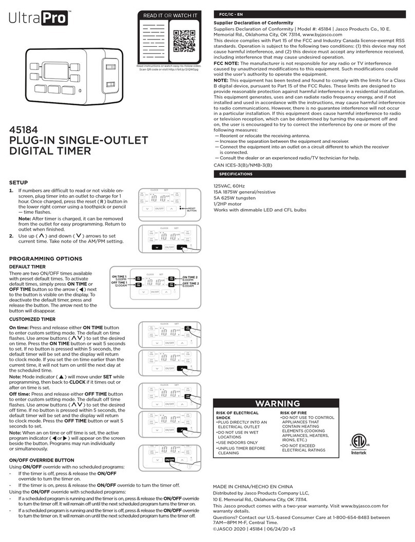
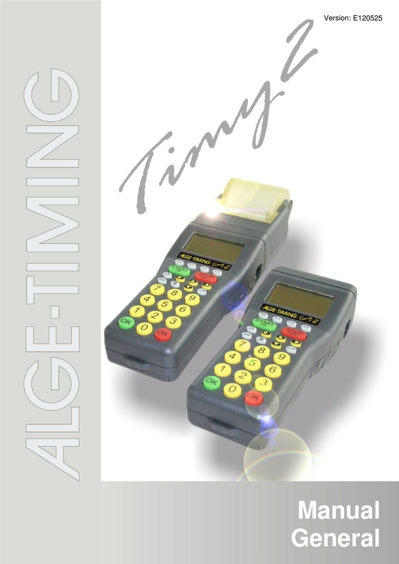
Diehl Program Timers User manual

Operating Manual Program Timers Variotime Single and Variotime Twin
Diehl AKO Stiftung & Co.KG Appliance Europe Pfannerstraße 75-83 DE – 88239 Wangen
Tel. +49 (7522) 73-0 • Fax +49 (7522) 73-250 • info@diehl-controls.com • www.diehl.com/controls/appliance
Subject to change without notice – issued 04-2015 – page 1/20
Operating Manual
Program Timers
Variotime Single
Variotime Twin
Fig. 1: Variotime Single first from left with optional accessories mounted
Variotime Twin first from right
Please note:
This operating manual is designated for use by our OEM customers and as
supporting material for their own appliance manuals.

Operating Manual Program Timers Variotime Single and Variotime Twin
Diehl AKO Stiftung & Co.KG Appliance Europe Pfannerstraße 75-83 DE – 88239 Wangen
Tel. +49 (7522) 73-0 • Fax +49 (7522) 73-250 • info@diehl-controls.com • www.diehl.com/controls/appliance
Subject to change without notice – issued 04-2015 – page 2/20
Table of contents
1 General ......................................................................................................... 3
1.1 Safety instructions ........................................................................................... 3
1.2 Your timer ...................................................................................................... 3
1.3 Functions of the program timer Variotime .......................................................... 4
2 Description of t e functional elements ........................................................ 5
2.1 Connections .................................................................................................... 5
2.1.1 Variotime Single with build-in housing ............................................................... 5
2.1.2 Variotime Twin with build-in housing ................................................................. 5
2.1.3 Variotime with panel-mount housing ................................................................. 5
2.2 Functional elements......................................................................................... 6
2.2.1 Variotime Single with 7 day program ................................................................. 6
2.2.2 Variotime Single with 24 hour program ............................................................. 7
2.2.3 Variotime Twin ................................................................................................ 8
2.3 Display symbols .............................................................................................. 9
2.4 Installation and connection .............................................................................. 9
2.4.1 Variotime with build-in housing......................................................................... 9
2.4.2 Variotime with panel-mount housing ................................................................ 10
3 Operating Variotime ................................................................................... 11
3.1 Initial power up .............................................................................................. 11
3.1.1 Setting the day of the week and ...................................................................... 11
the time of day .............................................................................................. 11
3.1.2 Channel indication .......................................................................................... 12
3.1.3 Power failure ................................................................................................. 12
3.2 Setting the operating modes ........................................................................... 13
3.2.1 Continuous operation mode ............................................................................ 13
3.2.2 Deactivation mode ......................................................................................... 14
3.2.3 Automatic mode ............................................................................................. 15
3.3 Setting the switching points ............................................................................ 15
3.4 Reset function ................................................................................................ 17
3.5 Skip function .................................................................................................. 17
4 Tec nical Data ............................................................................................ 19

Operating Manual Program Timers Variotime Single and Variotime Twin
Diehl AKO Stiftung & Co.KG Appliance Europe Pfannerstraße 75-83 DE – 88239 Wangen
Tel. +49 (7522) 73-0 • Fax +49 (7522) 73-250 • info@diehl-controls.com • www.diehl.com/controls/appliance
Subject to change without notice – issued 04-2015 – page 3/20
1General
Please read this manual carefully before installing connecting and operating Variotime.
1.1 Safety instructions
•T is timer must be installed by a qualified electrician only.
•Danger to life! T is timer is powered by t e mains supply printed on t e label. First
install t e timer into an appliance before connecting it to t e mains. Never touc t e
live contacts and/or t e components at t e open back of t e timer, and install it in
suc a way t at touc ing t e live parts at t e open back of t e timer is made
impossible during due application of t e appliance in w ic it is installed.
•T e outputs of t e 12 V and 24 V variants do not correspond to t e conditions of
SELV (safety extra-low voltage). T e supply voltage of t e appliance in w ic suc a
timer is installed must only be SELV, if t e outputs also switc SELV.
•Protection against accidental contact must be ensured by proper installation of t e
timer.
Install t e timer in suc a way t at t e end user of t e appliance in w ic it is
installed will be unable - during due application of t e appliance - to pull t e timer
out of t e appliance front, as in t is case t e live contacts at t e back of t e timer
would be exposed.
•T e timer must not come into contact wit water.
•Do not use t e timer to operate appliances w ic require supervision during
operation.
1.2 Your timer
Variotime is an electronic program timer designed for installation into electrical appliances or
devices. T e timer must not be operated wit out prior installation into a protective
ousing.
Variotime Single
Variotime Twin
Diehl AKO Stiftung & Co. KG Appliance Europe Pfannerstraße 75-83 DE-88239 Wangen

Operating Manual Program Timers Variotime Single and Variotime Twin
Diehl AKO Stiftung & Co.KG Appliance Europe Pfannerstraße 75-83 DE – 88239 Wangen
Tel. +49 (7522) 73-0 • Fax +49 (7522) 73-250 • info@diehl-controls.com • www.diehl.com/controls/appliance
Subject to change without notice – issued 04-2015 – page 4/20
1.3 Functions of t e program timer Variotime
Variotime is an electronic timer with 24 hour and/or 7 day program switching an electric appliance
on and off at programmed times.
Variotime switches an electric appliance via a relay. During a programmable period the relay
contacts are closed closing the electrical circuit and activating the appliance in which the timer is
installed. At the end of this period the relay contacts open again breaking the electrical circuit
and deactivating the appliance.
Variotime Single has one relay for switching one load (1 “channel”).
Variotime Twin has two relays for switching two loads (2 “channels”) independently however with
the full scope of functions for each channel.
Scope of functions:
•Time of day in 24 hour or 12 hour format (am/pm)
•7 day program optional 24 hour program only
•16 switching points (8 x ON 8 x OFF)
•Up to 112 switchings per week by forming program blocks
•Reset function
•Skip function

Operating Manual Program Timers Variotime Single and Variotime Twin
Diehl AKO Stiftung & Co.KG Appliance Europe Pfannerstraße 75-83 DE – 88239 Wangen
Tel. +49 (7522) 73-0 • Fax +49 (7522) 73-250 • info@diehl-controls.com • www.diehl.com/controls/appliance
Subject to change without notice – issued 04-2015 – page 5/20
2Description of t e functional elements
2.1 Connections
2.1.1 Variotime Single wit build-in ousing
①
②
Mains supply contacts
③
⑤
Relay contacts
2.1.2 Variotime Twin wit build-in ousing
①
②
Mains supply contacts
③④⑤
Relay contacts
2.1.3 Variotime wit panel-mount ousing
①
②
Mains supply contacts
③
⑤
Relay contacts
Fig. 2: Connections of Variotime Single
with build
-
in housing
(shown as ON/OFF version: changeover contact no. 4 not
placed)
Fig. 3: Connections of Variotime Twin with panel
-
mount housing
(shown as Version with 1 changeover relay)
Fig.
4
: Connections of Variotime Single
with panel
-
mount housing
(shown as ON/OFF version: changeover contact no. 4 not
placed)
1
2
5
3

Operating Manual Program Timers Variotime Single and Variotime Twin
Diehl AKO Stiftung & Co.KG Appliance Europe Pfannerstraße 75-83 DE – 88239 Wangen
Tel. +49 (7522) 73-0 • Fax +49 (7522) 73-250 • info@diehl-controls.com • www.diehl.com/controls/appliance
Subject to change without notice – issued 04-2015 – page 6/20
2.2 Functional elements
2.2.1 Variotime Single wit 7 day program
⑥
LC display
⑦
Slide switch for setting the operating
mode:
I = continuous ON
AUTO = automatic program
0 = continuous OFF
⑧
Slide switch for setting times:
position for setting the time of day
and the day of the week
RUN position: clock and automatic
program activated
position: programming mode
activated
⑨
button to select the switching points
when in programming mode
⑩
Day button
f
or setting the days of the
week
Hour button h for setting the hours
R button (reset) for deleting all settings
Minute button m for setting the minutes
⑭
Skip button to immediately reverse
the present operating mode
Instead of the language neutral numbering 1-2-3-….7 the days of the week may also be printed
as English abbreviations (M-T-W-Th-F-S-Su) on the housing rim above the display.
The day button may alternatively be denominated DAY.
The hour and minute buttons h and m may alternatively be denominated HR and MIN.
Fig. 5: Functional elements of Variotime Single
with 7 day program
⑦
⑧
⑩
⑪
⑫
⑥
⑬
⑭
⑨
1

Operating Manual Program Timers Variotime Single and Variotime Twin
Diehl AKO Stiftung & Co.KG Appliance Europe Pfannerstraße 75-83 DE – 88239 Wangen
Tel. +49 (7522) 73-0 • Fax +49 (7522) 73-250 • info@diehl-controls.com • www.diehl.com/controls/appliance
Subject to change without notice – issued 04-2015 – page 7/20
2.2.2 Variotime Single wit 24 our program
⑥
LC display
⑦
Slide switch for setting the operating
mode:
I = continuous ON
AUTO = automatic program
0 = continuous OFF
⑧
Slide switch for setting times:
position for setting the time of day and
the day of the week
AUTO position: clock and automatic
program activated
position: programming mode activated
⑨
button to select the switching points
when in programming mode
⑩
Plus button for setting times
Minus button for setting times
R button (reset) for deleting all settings
Skip button to immediately reverse the
present operating mode (printed as OVER
RIDE in this version only)
Fig. 6: Functional elements of Variotime Single
with 24 hour program
⑦
⑧
⑨
⑩
⑪
⑫
⑥
⑬
1

Operating Manual Program Timers Variotime Single and Variotime Twin
Diehl AKO Stiftung & Co.KG Appliance Europe Pfannerstraße 75-83 DE – 88239 Wangen
Tel. +49 (7522) 73-0 • Fax +49 (7522) 73-250 • info@diehl-controls.com • www.diehl.com/controls/appliance
Subject to change without notice – issued 04-2015 – page 8/20
2.2.3 Variotime Twin
⑥
LC display
⑦
Slide switch for setting the operating
mode:
I = continuous ON
AUTO = automatic program
0 = continuous OFF
⑧
Slide switch for setting the times:
RUN position: clock and automatic
program activated
P1 position: programming mode for
channel 1 activated
P2 position: programming mode for
channel 2 activated
⑨
button to select the switching points
when in programming mode
⑩
Day button for setting the days of the
week
Hour button h for setting the hours
R button (reset) for deleting all settings
Minute button m for setting the minutes
⑭
Skip button
to immediately reverse
the present operating mode
Fig. 7: Functional elements of Variotime Twin
⑥
⑨
⑩
⑪
⑫
⑬
⑭
⑦
⑧

Operating Manual Program Timers Variotime Single and Variotime Twin
Diehl AKO Stiftung & Co.KG Appliance Europe Pfannerstraße 75-83 DE – 88239 Wangen
Tel. +49 (7522) 73-0 • Fax +49 (7522) 73-250 • info@diehl-controls.com • www.diehl.com/controls/appliance
Subject to change without notice – issued 04-2015 – page 9/20
2.3 Display symbols
Additionally to the four-digit indication of the time of day the Variotime display features the
following symbols:
Day indicator
(
shown: Tuesday
)
in
7 day program
versions only
1
And/or
2
Indication of the active channel (shown: channel 1)
Variotime Single: always indicates channel 1
Variotime Twin: indicates channel 1 and/or 2
Light bulb symbol to distinguish the switching points
In programming mode:
ON: ON switching point is being programmed
OFF: OFF switching point is being programmed
In automatic mode:
ON: indicated channel is currently ON
OFF: indicated channel is currently OFF
I
S
witching point
number
(shown:
switching point 1 ON)
ON: when programming switching point 1
OFF: in automatic mode
Skip function activated
PM
or
AM
Only in versions with 12 hour time format
2.4 Installation and connection
When installing the program timer please observe the respective detailed drawing regarding
dimensions and electrical connections.
2.4.1 Variotime wit build-in ousing
1. Connect the relay or both relays (loads) via contacts ③ to ⑤. The on/off versions have
only the contacts ③ and ⑤ placed a changeover version has the contacts ③ ④ and ⑤
placed. Please observe the product label on your timer.
Fig
.
8
:
Variotime display with
24 hour time format
Fig
.
9
:
Variotime display with 12 hour
time format (am/pm)
PM
AM

Operating Manual Program Timers Variotime Single and Variotime Twin
Diehl AKO Stiftung & Co.KG Appliance Europe Pfannerstraße 75-83 DE – 88239 Wangen
Tel. +49 (7522) 73-0 • Fax +49 (7522) 73-250 • info@diehl-controls.com • www.diehl.com/controls/appliance
Subject to change without notice – issued 04-2015 – page 10/20
2. Connect the program timer to the mains supply via the contacts ① and ②.
3. Push the timer from behind into its allocated panel cutout and fasten it with four screws.
2.4.2 Variotime wit panel-mount ousing
Two each fixing brackets Diehl Controls material no. 413271110 (see Fig. 1) serve to easily mount
the timer at the back of a panel. The notched dovetail-guides engaging into the sides of the timer
housing allow secure mounting notwithstanding the panel thickness.
A transparent cover Diehl Controls material no. 413271185 is available as optional accessory. It
can be snapped onto the Variotime housing (see Fig. 1).
1. Push the timer into the panel cutout (66 x 66
mm) of your appliance from the front.
2. Fasten the timer from behind using the two fixing
brackets. Push them into the dovetail guides at
the housing sides so that their arms point
towards the panel. Push them forward until their
arms wedge the timer to the panel.
3. Connect the relay or both relays (loads) via contacts ③ to ⑤. The on/off versions have
only the contacts ③ and ⑤ placed a changeover version has the contacts ③ ④ and ⑤
placed. Please observe the label on your timer.
4. Connect the timer to the mains supply via the contacts ① and ②.
Fig. 12: Installation with fixing brackets
Fig
.
11
:
Installation of Variotime
with panel-
mount housing
Schalttafelgehäuse
Fig
.
10
:
Installation of Variotime with
build-in housing

Operating Manual Program Timers Variotime Single and Variotime Twin
Diehl AKO Stiftung & Co.KG Appliance Europe Pfannerstraße 75-83 DE – 88239 Wangen
Tel. +49 (7522) 73-0 • Fax +49 (7522) 73-250 • info@diehl-controls.com • www.diehl.com/controls/appliance
Subject to change without notice – issued 04-2015 – page 11/20
3 Operating Variotime
As the operation of the timer versions
•Variotime Single standard version with 24 hour and/or 7 day program
•Variotime Single special version with 24 hour program only
•Variotime Twin standard version with 24 hour and 7 day program
is widely identical notwithstanding the housing type or the time format these versions will
explicitly be mentioned only if necessary.
The timer is fully operable only after connection to the mains supply completion of the
connections mentioned in section 2.3 and setting of the time of day and the day of the week.
3.1 Initial power up
When connecting Variotime to the mains all display segments appear for approx. 2 seconds.
Subsequently the display flashes “0:00” and the day indicator at day 1 (= Monday). This
indication remains as long as the program timer stays connected to the mains waiting for the
input of time of day and day of the week.
3.1.1 Setting t e day of t e week and
t e time of day
Proceed as follows:
1. Variotime Single: set the right-hand slide switch to position.
Variotime Twin: set the right-hand slide switch to position RUN and press the buttons h and
m simultaneously for approximately 2 to 3 seconds.
The display stops flashing.
2. Press the day button and set the day of the week as follows:
1 = Monday 3 = Wednesday 5 = Friday 7 = Sunday
2 = Tuesday 4 = Thursday 6 = Saturday
With every pressing action the day indicator advances one day. If the day button is
pressed continuously the day indicator keeps advancing until button is released again.
24 hour version: not applicable.
3. Set the present time of day via the buttons h and m (24 hour version: buttons plus or
minus).

Operating Manual Program Timers Variotime Single and Variotime Twin
Diehl AKO Stiftung & Co.KG Appliance Europe Pfannerstraße 75-83 DE – 88239 Wangen
Tel. +49 (7522) 73-0 • Fax +49 (7522) 73-250 • info@diehl-controls.com • www.diehl.com/controls/appliance
Subject to change without notice – issued 04-2015 – page 12/20
Keeping the buttons pressed for longer than 2 seconds activates the fast setting mode
which stops when they are released again.
4. Set the right-hand slide switch to RUN position (24 hour program: AUTO position).
The program timer accepts the time setting. The colon in the time display starts to flash.
From now on the time of day will run on accurately to the second.
Variotime Twin: approximately 15 seconds after the setting has been completed the
program timer accepts the time setting. The colon in the time display starts to flash. From
now on the time of day will run on accurately to the second.
Repeat steps 1 to 4 to change the day of the week and/or the time of day.
3.1.2 C annel indication
Variotime Single features one channel that is one relay for controlling a single load. Therefore
the timer display shows “1” by default on the upper right next to the digits indicating the time of
day (see 2.3).
Variotime Twin features a two channels (two relays). Therefore it can control two loads
independently at the same time. The channel which is actively executing an automatic program is
displayed as “1” or “2” on the upper right next to the digits indicating the time of day (see 2.3). If
both channels are active they are being displayed side by side as “12”.
3.1.3 Power failure
In case of a power failure Variotime will retain the time of day and the day of the week for a
minimum of 5 minutes. The longer the program timer has been connected to the mains and has
been able to charge prior to the failure the longer is its buffer time. The automatic program
remains stored in the memory but cannot be executed.
If the power returns within the buffer time Variotime will keep on running normally and will
resume the automatic switching program.
If the power failure exceeds the buffer time the last stored automatic program remains in the
memory however Variotime loses the time of day and the day of the week. When the power
returns these have to be set first before the program timer can resume the automatic switching
program.

Operating Manual Program Timers Variotime Single and Variotime Twin
Diehl AKO Stiftung & Co.KG Appliance Europe Pfannerstraße 75-83 DE – 88239 Wangen
Tel. +49 (7522) 73-0 • Fax +49 (7522) 73-250 • info@diehl-controls.com • www.diehl.com/controls/appliance
Subject to change without notice – issued 04-2015 – page 13/20
3.2 Setting t e operating modes
The three principal operating modes of Variotime are
•continuous operation mode
•deactivation mode
•automatic operation mode
The operating mode is set with the left-hand slide switch.
3.2.1 Continuous operation mode
In this mode the appliance in which Variotime is installed is switched on continuously. Any
automatic program is deactivated.
Variotime Single
Proceed as follows:
1. Set the left- hand slide switch to position I.
The relay switches on if it was off before. On the right side of the time digits 1 (= channel
1) and the light bulb symbol appear.
If the relay was on before the indication does not change and will stay the same as long as
this mode continues.
2. Terminate the continuous operation by setting the slide switch to position AUTO.
The timer resumes the automatic program and displays the present status accordingly.
Variotime Twin
In this version both channels can be set to continuous operation independently. Possible
combinations are:
•channel 1 in continuous operation mode and channel 2 unchanged
•channel 2 in continuous operation mode and cannel unchanged
•Both channels in continuous operation mode
Proceed as follows:
1. Set the left-hand slide switch to position I.
2. Press the skip button to select the desired channel:

Operating Manual Program Timers Variotime Single and Variotime Twin
Diehl AKO Stiftung & Co.KG Appliance Europe Pfannerstraße 75-83 DE – 88239 Wangen
Tel. +49 (7522) 73-0 • Fax +49 (7522) 73-250 • info@diehl-controls.com • www.diehl.com/controls/appliance
Subject to change without notice – issued 04-2015 – page 14/20
pressing the skip button once selects channel 1. The channel indicator 1 flashes. After
approximately 3 seconds 1 stops flashing and the light bulb symbol appears.
pressing the skip button twice selects channel 2. The channel indicator 2 flashes. After
approximately 3 seconds 2 stops flashing and the light bulb symbol appears.
The order of setting the channels is not important. If both channels are in continuous
operation mode the display will show “12” and the light bulb symbol steadily.
3. Terminate the continuous operation mode of both channels by setting the slide switch to
the position AUTO.
The timer resumes the automatic program and displays the present status accordingly.
Change a current setting by terminating first and resetting again.
3.2.2 Deactivation mode
In this mode the appliance in which Variotime is installed is switched off continuously. Any
automatic program is deactivated.
Variotime Single
Proceed as follows:
1. Set the left-hand slide switch to position 0.
The relay switches off if it was on before. On the right side of the time digits 1 (= channel
1) flashes as long as this mode continues.
2. Reactivate the automatic program by setting the left-hand slide switch back to position
AUTO.
The timer resumes the automatic program and displays the present status accordingly.
Variotime Twin
In this version both channels can be deactivated independently. Possible combinations are:
•channel 1 deactivated and channel 2 unchanged
•channel 2 deactivated and cannel 1 unchanged
•Both channels deactivated
Proceed as follows:
1. Set the left-hand slide switch to position 0.

Operating Manual Program Timers Variotime Single and Variotime Twin
Diehl AKO Stiftung & Co.KG Appliance Europe Pfannerstraße 75-83 DE – 88239 Wangen
Tel. +49 (7522) 73-0 • Fax +49 (7522) 73-250 • info@diehl-controls.com • www.diehl.com/controls/appliance
Subject to change without notice – issued 04-2015 – page 15/20
2. Press the skip button to select the desired channel:
pressing the skip button once selects channel 1. The channel indicator 1 flashes.
pressing the skip button twice selects channel 2. The channel indicator 2 flashes.
The order of setting the channels is not important. If both channels are in deactivation
mode 1 and 2 flash simultaneously and will continue to do so until this mode is terminated.
3. Reactivate both channels by setting the left-hand slide switch to position AUTO.
The timer resumes the automatic program and displays the present status accordingly.
Change a current setting by terminating first and resetting again.
3.2.3 Automatic mode
In the automatic mode the appliance in which Variotime is installed is being controlled according
to the inputted program. The display shows the present status. During normal program execution
the left-hand slide switch is in position AUTO and the right-hand slide switch is in position RUN (24
hour program: AUTO).
3.3 Setting t e switc ing points
Generally Variotime can be programmed with 16 switching points per channel (8 ON and 8 OFF)
spread over 24 hours. The switching points are numbered as follows:
•switching points with uneven numbers (1 3 5 7 9 11 13 and 15) are ON points. They
are indicated by the light bulb symbol in the display.
•switching points with even numbers (2 4 6 8 10 12 14 and 16) are OFF points. The
light bulb symbol is off.
In order to avoid errors in the program logic the switching points should always be programmed
in pairs that is always an ON point and subsequently the corresponding OFF point.
The 112 switchings per week result from the possibility to assign identical switching points to
several days of the week. Diehl Controls advises to set up a time schedule first as a basis to input
a complex block program for several days. For setting use the day button with the following
combinations:
•single days of the week
1 = Monday 2 = Tuesday 3 = Wednesday 4 = Thursday 5 = Friday
6 = Saturday 7 = Sunday
•day block 12345 = daily from Mondays through to Fridays
•day block 67 = daily on Saturdays and Sundays

Operating Manual Program Timers Variotime Single and Variotime Twin
Diehl AKO Stiftung & Co.KG Appliance Europe Pfannerstraße 75-83 DE – 88239 Wangen
Tel. +49 (7522) 73-0 • Fax +49 (7522) 73-250 • info@diehl-controls.com • www.diehl.com/controls/appliance
Subject to change without notice – issued 04-2015 – page 16/20
•day block 123456 = daily from Mondays through to Saturdays
•day block 1234567 = daily from Mondays through to Sundays (7 days a week)
Each pressing of the day button advances the day indicator by one day until day 7 is reached.
Then the day blocks are called up one after the other resuming again with the single days at day
1.
In the 24 hour version the 16 switching points are spread over 24 hours only.
In Variotime Twin the full 16 switching points are available for both channels independently.
The shortest interval between the switching points is 1 minute.
Proceed as follows:
1. Variotime Single: set the right-hand slide switch to position .
Variotime Twin: set the right-hand slide switch to position P1 (channel 1) or P2 (channel
2). Both channels have to be programmed individually.
The display flashes “0:00” on the top right the (selected) channel is indicated on the
bottom right “I” is indicated (switching point 1 ON). The light bulb symbol appears.
2. Set the time for the switch on point using the buttons h and m then assign it to the days
of the week by pressing the day button. The order of the settings is not important.
3. Pressing the button advances Variotime to the next switching point 2 (OFF).
The display flashes “0:00” on the top right the (selected) channel is indicated on the
bottom right “2” is indicated (switching point 2 OFF).
4. Set the time for the switch poff point using the buttons h and m then assign it to the days
of the week by pressing the day button. The order of the settings is not important.
5. Pressing the button advances Variotime to the next switching point 3 (ON).
Repeat steps 1 to 4 until all times for switching on and off have been programmed (16
maximum) in the same manner.
6. Reset the right-hand slide switch to the position RUN (24 hour version: AUTO).
The display reverts to the present time of day and day of the week. Supposing that the left-hand
slide switch is in position AUTO Variotime immediately executes the program set for the present
time and indicates the status as described above. From now on Variotime will follow the inputted
automatic program day for day and week for week until the settings are changed.
To check or change switching points proceed as follows:
7. Set the right-hand slide switch to position (Variotime Twin: P1 or P2).
8. Select the individual switching points by pressing the button repeatedly.

Operating Manual Program Timers Variotime Single and Variotime Twin
Diehl AKO Stiftung & Co.KG Appliance Europe Pfannerstraße 75-83 DE – 88239 Wangen
Tel. +49 (7522) 73-0 • Fax +49 (7522) 73-250 • info@diehl-controls.com • www.diehl.com/controls/appliance
Subject to change without notice – issued 04-2015 – page 17/20
Follow this procedure to check of change switching points any time.
9. Having finished set the right-hand slide switch back to position RUN (24 hour program:
AUTO).
To cancel individual switching points proceed as follows:
10. Set the right-hand slide switch to position (Variotime Twin: P1 orr P2).
11. Press button repeatedly until the relevant switch on point is selected.
12. Now press the skip button and the button simultaneously for approximately 2 or 3
seconds. The display flashes „0:00“ showing the switching point has been canceled.
13. Proceed likewise to cancel the linked switch off point to avoid logic errors.
14. Set the right-hand slide switch back to position RUN (24 hour program: AUTO).
To cancel the entire automatic program use the reset function (see 3.4).
3.4 Reset function
The reset function is recommended for extensive changes in the automatic program. It cancels the
previous input entirely and resets the timer into initial power up status. So a new program can be
created without having to access the individual switching points.
In order to avoid resetting the timer inadvertendly the button R is recessed and has to be pressed
using a ball pen or similar instrument.
Proceed as follows:
1. Press the button R. All indications in the display disappear it flashes “0:00” and the day
indicator at day 1. The automatic program is canceled completely.
2. Now set the present time of day and the day of the week again as described in 3.1.
Variotime is ready for a new program.
3.5 Skip function
The skip function reverses the current operating mode of the appliance in which Variotime is
installed with immediate effect and is canceled automatically on reaching the next switching point.
It serves to override individual switching points without having to change the automatic program.

Operating Manual Program Timers Variotime Single and Variotime Twin
Diehl AKO Stiftung & Co.KG Appliance Europe Pfannerstraße 75-83 DE – 88239 Wangen
Tel. +49 (7522) 73-0 • Fax +49 (7522) 73-250 • info@diehl-controls.com • www.diehl.com/controls/appliance
Subject to change without notice – issued 04-2015 – page 18/20
Example:
Variotime is in ON mode that is according to the automatic program the appliance in which the
timer is installed is presently switched on. Pressing the skip button immediately switches the
appliance off remaining so until the skip button is either pressed again or the next switching
point is reached. This switching point is being executed again according to the automatic program.
Staying with the example the appliance remains switched off until the next switch on point is
reached.
Vice versa a switched off appliance is switched on by pressing the skip button . When
reaching the next switching point the skip function is canceled however the appliance remains on
as a switch off point is always followed by a switch on point.
Variotime Single
Proceed as follows:
1. Press the skip button once. The appliance changes into the opposite operation mode.
The skip symbol appears in the display so does the light bulb symbol if the
appliance was off before or it disappears if the appliance was on before.
Variotime Twin
Proceed as follows:
1. Press the skip button once. The channel indicator 1 flashes and the load connected to
channel 1 is switched.
Press the skip button twice. The channel indicator 2 flashes and the load connected to
channel 2 is switched.
After approximately 3 seconds the channel indication stops flashing and the skip symbol
appears in the display so does the light bulb symbol if the load was off before or it
disappears if the load was on before.
This operation mode continues until the next switching point is reached which will be executed
according to the program. The skip symbol disappears.
2. To cancel the skip function press the skip button again as described above. The skip
symbol disappears and Variotime reverts to the current operation mode according to its
programming.

Operating Manual Program Timers Variotime Single and Variotime Twin
Diehl AKO Stiftung & Co.KG Appliance Europe Pfannerstraße 75-83 DE – 88239 Wangen
Tel. +49 (7522) 73-0 • Fax +49 (7522) 73-250 • info@diehl-controls.com • www.diehl.com/controls/appliance
Subject to change without notice – issued 04-2015 – page 19/20
4 Tec nical Data
Functions
Time program 7 day program 24 hour program only optional
Time format 24 hours or 2x 12 hours (am/pm)
Reset function yes
Shortest switching interval 1 minute
Operating modes ON OFF Automatic
Product features
Programmable switching
points
16 (8x ON 8x OFF).
Forming program blocks for days with
the same switching schedule results in a max. of 112
switching points per week (56x ON 56x OFF)
Display 7 day indicators 4-digit time display 2-
digit indication of the
activated channel(s) 2-digit indication of the
switching point
indication of operation mode and skip function with symbols
AM/PM indication with 12 hour time format
Operation Via 6 buttons and 2 slide switches with 3 positions each
Quantity of relays 1 (Variotime Single) or 2 (Variotime Twin)
Tec nical Data
Rated voltage 220-240 V AC 110-120 V AC 12 V AC/DC 24 V AC/DC
Rated frequency 50/60 Hz
Stand by power consumption < 0.5 W
Buffer time
5 minutes
Switch rating Variotime Single with build-in housing: 1x 10 A/250 V AC
Variotime Single with panel-mount housing: 1x 16 A/250 VAC
Variotime Twin: 2x 5(2) A/250 V AC
Max. ambient temperature T55°C
Outer dimensions Variotime with build-in housing: 62 x 62 x 30.5 mm
Variotime with panel-mount housing: 72 x 72 mm
Details see relevant timer drawing

Operating Manual Program Timers Variotime Single and Variotime Twin
Diehl AKO Stiftung & Co.KG Appliance Europe Pfannerstraße 75-83 DE – 88239 Wangen
Tel. +49 (7522) 73-0 • Fax +49 (7522) 73-250 • info@diehl-controls.com • www.diehl.com/controls/appliance
Subject to change without notice – issued 04-2015 – page 20/20
Additional data for Variotime
with panel-mount housing
only
Purposes/construction Time control electronic incorporated
Mounting Fitting into a panel opening
Mode of action Type 1.B.S
Degree of contamination 3
Rated impulse voltage 2500 V (Input 110-120 V ac)
800 V (Input 24 V or 12 V)
4000 V (Output 250 V ac)
Connections
Mains and power relays Tab terminals 6.3 x 0.8 mm in compliance with EN 61210
Approvals VDE – ENEC and UL/CSA (technical conditions apply)
This manual suits for next models
2
Table of contents
