Europa components ET167DYD User manual
ET167DYD
Operating Instructions
Important notice to installers!
Before installation work starts the operating instructions should be read and understood.
If you need technical assistance please contact the manufacturer at the address shown on this leaflet.
Installation of this unit should only be undertaken by a skilled electrician working to the
standards set by the latest edition of the IEE wiring regulations.
The unit is designed to withstand reasonable levels of interference from external sources
such as voltage peaks in the electricity supply. If however the supply is known to be subject to
unusual level of interference then measures to protect the device from this need to be taken by
the installer. Similarly the output relay is designed to switch a resistive load. If inductive or
capacitive loads need to be switched it is suggested that a suitably specified slave device
such as a contactor or relay be used to carry out the switch duty.
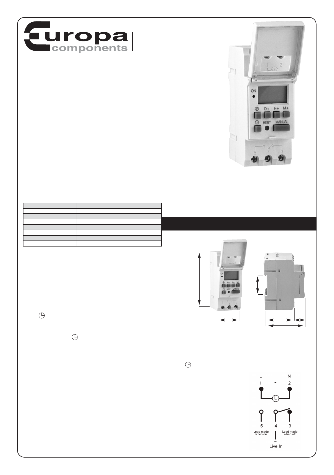
Electrical connections
240V mains supply to terminals 1 & 2
Switched, volt free, output is across terminals 3, 4 & 5 where terminal 4 is common.
The switch across terminal 4 & 5 is made when the timer is ON
The switch across terminal 4 & 3 is made when the timer is OFF
Mounting the Unit
The device is rated at IP 20 and as such provides finger protection but no immunity to fluids. It is designed to be fitted on a Din rail within a
suitably IP rated enclosure. Visit www.europacomponents.com to select an enclosure from the broad range on offer.
Efforts should be made to ensure that the device is not subjected to undue vibration. Methods such as resilient mounting of the enclosure
should be employed to keep levels to a minimum.
Technical Data
Initial setup
In order to programme the unit the internal battery will need to be charged.
To do this you will need to connect a live feed to the unit for about ten minutes.
The set up procedure can then be done with the power disconnected.
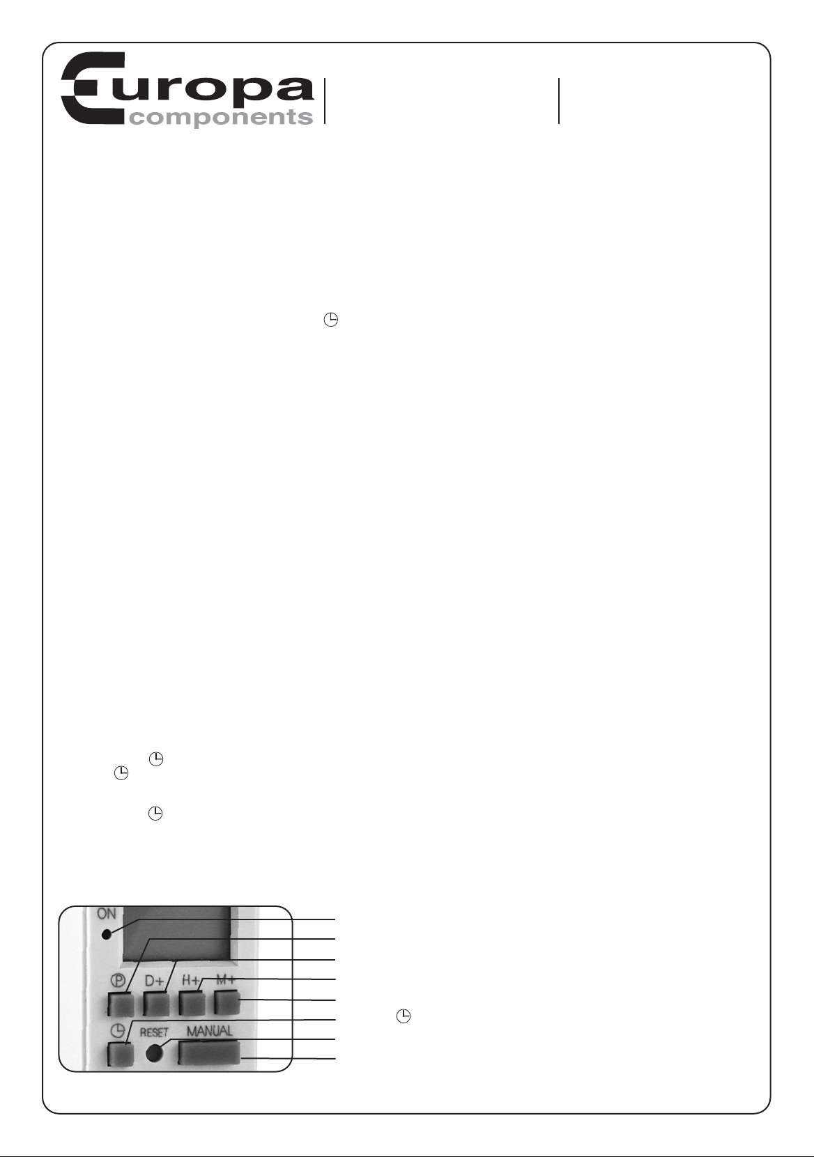
Guide to the Programming Keys
Button ‘D’ Sets the Day
Button ’H’ Sets the Hour
Button ‘Min’ Set the number of minutes
Button ‘P’ Enables Programming
Button ‘R’ Resets the device
Button ‘Manual’ Sets the device to ON-AUTO-OFF. Also cancels out functions.
Button ‘ ’ Master clock
Red LED Illuminated when relay is in ON state
Setting the master clock
Press the clock button ‘ ’ and hold down whilst also pressing the following buttons.
Press the ‘D’ button until the triangle on the top of the screen moves to the correct day as shown at the top of the picture frame.
Press the ‘H’ button until the correct hour is shown on the 24 hour clock
Press the ‘Min’ button until the correct number is displayed
To change the display from 24 hour (Default setting) to 12 hour clock press the ‘ ’ button for 3 seconds. AM or PM appear in the screen
showing that 12 hour format has been set.
What the timer can do
Up to 16 ON/OFF periods can be set for each day of the week.
Any one period can be set between 1 Minute and 168 Hours
To simplify the setting of the day or days that are required there are a number
of preset combinations of days within the programme. They are as follows:
Every day of the week
Monday to Saturday inclusive
Monday to Friday inclusive
Saturday and Sunday only
Monday, Tuesday & Wednesday
Thursday, Friday & Saturday
Monday, Wednesday & Friday
Tuesday, Thursday & Saturday
Individual days of the week such as Monday etc
Supply Voltage 230Volts 50/60Hz AC
Output relay rating 16Amps AC1 resistive
Output relay type Single pole changeover (volt free)
Power consumption <2VA
Set Period of relay 1 min to 168 Hours
Time Error <±0.5 Seconds per Day
Ambient temp range -25°C to +60°C
Operating Humidity <95%
ET167DYD Din Rail Mounting
Width 35mm
Height 86mm
Depth 47mm
Standard Din Rail Clip
17mm
Depth 64mm
ET167DYD_Instructions:Layout 1 7/11/12 15:30 Page 1
To Programme the Timer
Press the ‘P’ button & release it.
Set the day of days that you require the timer to operate from the list already described. The triangles at the top of the screen will show which
days have been selected.
Press the ‘H’ button to set the hour that you want the timer to operate at.
Press the ‘Min’ button to set the minute that you want the timer to operate at.
Press the ‘P’ button again and the OFF time can be set using the same method as setting the ON function just described above.
The timer will return to the master clock screen if no buttons are pressed for 30 seconds.
You have now set one ON/OFF period (#1).
To set additional periods press the ‘P’ button and then again to scroll to period#2 On , then again to #2 OFF and so to #16 if required.
To exit the programme function press the clock button this will return you to the master clock screen.
Enabling the programme to run
Press the ‘Manual’ button and the display will change from ON to ON-AUTO.
Pressing again will move to OFF and subsequent pressing will move to OFF AUTO and then again to ON.
To run the programme the timer needs to be set to either ON-AUTO or AUTO-OFF.
If you are setting the timer to run during a period when the timer is programmed to be off then the AUTO-OFF sheeting needs to be displayed.
If you are setting the timer to run during a period when the timer is programmed to be on the ON-AUTO setting needs to be displayed. IF ON
or OFF are displayed the timer will not operate to the programme set (see manual operation).
Cancelling programme periods
To cancel any programmed ON/OFF period. Press the ‘P’ button repeatedly until the Period number is shown that you wish to cancel or
change. Press the ‘C’ button and the screen will clear.
You will then be able to re-programme this period or leave it blank. Remember to clear both the ON and OFF instructions for any one period.
Resetting the timer clock
Pressing the button marked ’R’ will completely clear the master clock and all programmed periods in the memory of the device.
Manual Operation
Press the manual button to set the device to ON or OFF. This will override any programs that are set and force the timer into the set state ie
ON =on and OFF =off
Calibrating the clock
If the clock is found to be running fast, or slow it is possible to speed it up or slow it down.
Press the ‘Manual’ and ‘P’ buttons at the same time. Then press the ‘D’ button until a number between 0-30 shows this is the number of
seconds to be added in the week. Pressing the ‘D ‘ button again you can scroll until negative numbers are displayed. The negative number
displayed represents the number of seconds by which the clock will be slowed each week.
Countdown Function
It is possible to set the timer so that it counts down from a preset value.
Press the ’P’ and ‘ ’ buttons together for 3 seconds
Press the ‘ ‘ button and hold down whilst the ‘H’ and ‘M’ buttons are used to set the overall countdown period.
Press the ‘Manual’ button to start
Press the ‘P’ button to stop
Press the ’P’ and ‘ ’ buttons together for 3 seconds to exit the countdown function.
Switching the timer off and clearing the menu
Pressing the ‘H’ & ‘Min’ buttons at the same time for ten seconds will switch the timer off. The clock settings and all programmed events will
be cleared. To switch back on press the small ‘R’ button.
ET167DYD
Operating Instructions
Europa House
Airport Way
Luton, Beds, LU2 9NH
Tel: 01582 692 440 / Fax: 01582 692 450
e-mail: [email protected]
website: http://www.europacomponents.com
Red LED Illuminated when relay is in ON state
Button ‘P’ Enables Programming
Button ‘D’ Sets the Day
Button ’H’ Sets the Hour
Button ‘Min’ Set the number of minutes
Button ‘ ’ Master clock
Button ‘R’ Resets the device
Button ‘Manual’ Sets the device to ON-AUTO-OFF. Also cancels out functions.
Guide to Programming Keys
ET167DYD_Instructions:Layout 1 7/11/12 15:30 Page 2
Table of contents


