Digga MINI BIGFOOT User manual

1
SERVICE MANUAL
TRENCHERS
PM-000111-A

2PM-000111-A Trencher: Service and Repair Manual - November 2014

3
All BIGFOOT AND HIGHDRIVE TRENCHERS
This manual is intended to be used by persons with reasonably mechanical skills and understanding of mechanical components.
This manual will assist in the disassembly and assembly of the above model Trenchers. Item numbers, indicated in pa-rentheses throughout
this manual, refer to the exploded parts breakdown drawing. Individual customer specications may vary from exploded drawing and standard
part numbers shown. Contact Digga Australia for enquiries.
For any spare or replacement parts, contact Digga Service and Spares or a local Digga representative. For identication purposes always try
to have available the trencher type and serial number. This information may be necessary for verication of any component part numbers.
Component part numbers and/or manufacturing gear set numbers may be stamped on individual parts. This information may also be helpful in
identifying replacement components.
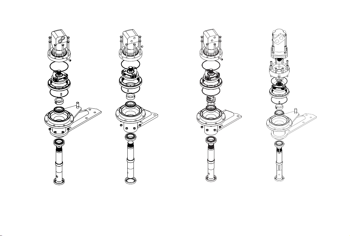
MODELS COVERED IN THIS MANUAL
MINI BIGFOOT BIGFOOT BIGFOOT XD HYDRIVE HYDRIVE XD

4PM-000111-A Trencher: Service and Repair Manual - November 2014
PLANETARY GEAR OIL
The Trencher Planetary Unit is a sealed Unit. If there is any sign of oil leaks please contact your nearest DIGGA dealer before carrying out
any repairs, as there can be other causes for seal leaks.
OPERATING IN ASIA PACIFIC AND EUROPE
The Planetary Drive Unit in the Trencher when operating in Asia Pacic and Europe uses the Gear Oil VALVOLINE EPG ISO 320
(mineral oil) for lubrication of gears and bearings. Minimum and maximum gear oil operating temperatures for these regions is
-5°C (23°F) to 120°C (248°F). Please contact your Digga specialist for the recommended Gear Oil if operating outside this range.
OPERATING IN NORTH AMERICA
The Planetary Drive Unit in the Trencher when operating in North America uses the Gear Oil CHEVRON MEROPA ISO 320
(mineral oil) for lubrication of gears and bearings. Minimum and maximum gear oil operating temperatures for this region is
-18°C (-0.4°F) to 107°C (225°F). Please contact your Digga specialist for the recommended Gear Oil if operating outside this range.
● Continuous operating temperature must not exceed 80°c.
● During extended stationary periods (one month or more), the unit should be run monthly to immerse all internals in oil, thereby
preventing corrosion.
● Oil should be changed when hot, to prevent a build up of sludge deposits. Flush interior of unit with uid recommended by oil
companies.
● Check for leaks regularly and if an oil leak is detected contact your nearest DIGGA Dealer for remedy instructions.
● Use only the prescribed oil when relling. Valvoline EPG ISO 320 Gear Oil.
● DO NOT mix oil of different viscosity, NOT even those of the same brand.
● NEVER mix mineral and synthetic oils.
● Cleanliness is necessary when changing oil.
IMPORTANT
• First oil change MUST be carried out within the rst 50 hours of use under MODERATE OPERATING CONDITIONS. Thereafter,
every 500 hours.
• Change the gear oil after the rst 30 hours of SEVERE OPERATING CONDITIONS*. (i.e. severe ambient temperature conditions of
+40°C or below 0°C, trenching in hard ground.) Thereafter, every 300 hours.
• Contact your nearest DIGGA Dealer for Gear Oil change procedure.
OIL CHANGED SCHEDULE
THE GEARBOX OIL CAPACITY IS ENGRAVED ONTO THE SERIAL TAG LOCATED ON THE TRENCHER

5
TABLE OF CONTENTS
OIL CHANGE SCHEDULE.............................................................................................................................. 4
TABLE OF CONTENTS................................................................................................................................... 5
DRIVE ASSEMBLY: DISASSEMBLY PROCEDURE..................................................................................... 6
DRIVE ASSEMBLY: MINI BIGFOOT - BIGFOOT - BIGFOOT XD - BIGFOOT XD HIGH FLOW............... 7
DRIVE ASSEMBLY: HYDRIVE - HYDRIVE XD............................................................................................. 8
PLANETARY SUBASSEMBLY........................................................................................................................ 9
UNIT REASSEMBLY....................................................................................................................................... 10
MAINTENANCE.............................................................................................................................................. 11
BEARING PRELOAD CHART........................................................................................................................ 18
MINI BIGFOOT SPARE PARTS..................................................................................................................... 19
BIGFOOT 900 DIG SPARE PARTS............................................................................................................... 22
BIGFOOT 700 DIG SPARE PARTS............................................................................................................... 25
BIGFOOT XD 900 DIG SPARE PARTS......................................................................................................... 28
BIGFOOT XD 1200 DIG SPARE PARTS....................................................................................................... 31
BIGFOOT XD 1500 DIG SPARE PARTS....................................................................................................... 34
HYDRIVE 900 DIG SPARE PARTS............................................................................................................... 37
HYDRIVE 1200 DIG SPARE PARTS.............................................................................................................. 40
HYDRIVE XD 1200 DIG SPARE PARTS........................................................................................................ 43
HEAD START CRUMBER SPARE PARTS..................................................................................................... 46
CHAIN SPARE PARTS.................................................................................................................................... 50
GEARBOX SPARE PARTS............................................................................................................................. 58
CONTACT INFORMATION............................................................................................................................. 70

6PM-000111-A Trencher: Service and Repair Manual - November 2014
DRIVE ASSEMBLY: DISASSEMBLY PROCEDURE
All parts should be inspected as they are removed from unit. Scribe or mark a line across the assembly mounting case, ring gear, and cover
joints on outside of gearbox to assure proper orientation of assembly, oil ll/ drain plug, motor mounting, etc., as the unit is reassembled.
1. Remove chain, boom, sprockets and seal protector.
2. Remove outer ring of bolts (refer to diagram below) from gearbox assembly. Lift gearbox assembly clear of frame. Remove drain plug and
drain oil.
3. Remove inner ring of bolts and nyloc nuts (Refer to pages 6 and 7). Remove hydraulic motor from gearbox assembly.
4. The primary planetary assembly is now ready for removal. Lift outer ring gear, sun gear and gear set from the output housing.
5. Remove key steel from keyway. Loosen lock nut using the required tool and remove locknut.
6. With output shaft down through a centre hole in hydraulic press table and unit supported by case, press shaft out by applying load to top
end of shaft (internal end) until it passes through inner shaft bearing. Outer shaft bearing will come out of unit attached to shaft.
The unit is now disassembled into groups of parts and/or subassemblies. The area requiring repair or service should be identied by thorough
inspection of the parts after they have been washed in solvent.
CAUTION: RETAINING RING IS NO LONGER RETAINING OUTPUT SHAFT. TAKE PRECAUTIONS IF THE UNIT IS MOVED
BECAUSE THE SHAFT MAY FALL OUT.
CAUTION: CARE SHOULD BE TAKEN NOT TO INJURE FEET OR DAMAGE OUTPUT SHAFT DURING THIS PROCEDURE.
7
DRIVE ASSEMBLY: BIGFOOT - BIGFOOT XD - BIGFOOT XD HIGH FLOW
REFER TO APPROPIATE EXPLODED VIEW DRAWING (Page 58-65)
1. Inspect inner and outer bearing cups and cones. If either is damaged, the complete bearing assembly will need replacing.
2. Remove inner and outer bearing races from output housing with the appropriate tool.
3. Clean all foreign material from oil plug located on bottom of output housing. Add a small amount of pipe thread compound to thread on plug
before installing it back into case.
BIGFOOTMINI BIGFOOT BIGFOOT XD BIGFOOT XD HIGHFLOW

8PM-000111-A Trencher: Service and Repair Manual - November 2014
DRIVE ASSEMBLY: HYDRIVE - HYDRIVE XD
REFER TO APPROPIATE EXPLODED VIEW DRAWING (Page 66-69)
1. Inspect inner and outer bearing cups and cones. If either is damaged, the complete bearing assembly will need replacing.
2. Remove inner and outer bearing races from output housing with the appropriate tool.
3. Clean all foreign material from oil plug located on bottom of output housing. Add a small amount of pipe thread compound to thread on plug
before installing it back into case.
HYDRIVE HYDRIVE XD
9
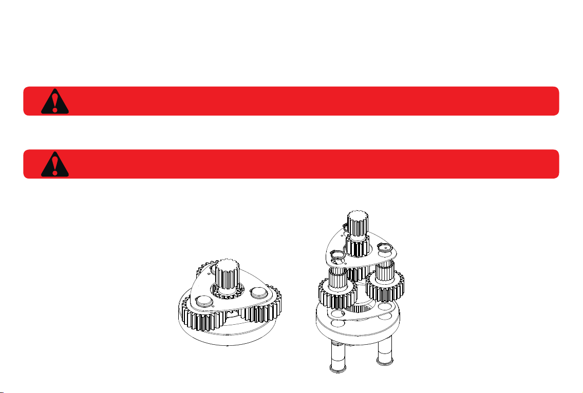
Rotate planet gear to check for any abnormal noises or roughness in the primary planet bearings. At the same time, inspect planet gears for any
damage or worn teeth. If replacement or further inspection is required, proceed as follows.
1. Remove circlips from top plate and remove plate.
2. Slide planet gears from carrier.
3. Remove bottom plate.
4. Check primary planet shafts, top and bottom plates, centre thrust washer, needle rollers and gears for any abnormal wear.
5. Replace any worn items.
6. Assembly: Fit centre thrust washer, t bottom plate, t gears, insert needle rollers into gears using lubricating oil, t top washer and install
circlips to posts place gear set into ring gear and place sun gear into gear set, ensure all turns freely.
CAUTION: THE NEEDLE ROLLER BEARINGS ARE NOT CAGED THEREFORE CAN FALL FREE.
NOTE: IF THE PLANET SHAFTS ARE WORN, THE COMPLETE CARRIER ASSEMBLY MUST BE REPLACED. THE POSTS
SHOULD NOT BE REPLACED IN AN EXISTING CARRIER.
PLANETARY SUBASSEMBLY

10 PM-000111-A Trencher: Service and Repair Manual - November 2014
UNIT REASSEMBLY
1. Start with output housing assembly. Turn case upside down and position on table. Bottom seal end should be facing upward and install
bearing cup with appropriate tooling.
2. Install bottom seal applying a smear of Loctite 243 thread locker to outside of seal and t using appropriate tooling. Ensure seal is ush
with the housing. Wipe off excess Loctite. Grease inner face of seal with EP grease.
3. Invert outer housing to upright position and place over securely positioned output shaft with splines facing upward. Using the appropriate
tooling, assemble the output housing onto the output shaft.
4. Install bearing race to output housing with appropriate tooling. Install bearing ensuring correct installation technique. Only drive the
bearing home via the inner cone of bearing. Hitting outer roller cage will damage the bearing.
5. While holding output shaft with one hand, rotate case to be certain it turns freely and smoothly. The slight resistance felt, if any, is due to
shaft seal load (drag) on output shaft. Nut tension – 125ft/lbs (approx) (“Bearing Preload Chart P.18” for correct lock nut tension.)
6. Insert key after tensioning locking nut.
7. Clean and ensure inner section of housing and bearings are free from foreign matter.
8. Lightly grease a new o-ring and install it into o-ring groove in case.
9. Fit gear set and sun gear to the output housing. Line up bolt holes and t ring gear. Make sure the ring gear sits at on the
housing. Top up gear oil level to top of gear set.
10. Grease a new o-ring and install it into the groove of hydraulic motor. Refer back to scribe marks made across external joints prior to
Disassembly Procedure. Line up scribe marks so that orientation of motor mount holes and oil plug are back to their original positions and
ret motor.
11. Re t gearbox assembly making sure original scribe marks are aligned and t all outer bolts.
12. Attach hydraulic hoses and test operation.
13. Ret seal protector, sprocket, boom and chain.
NOTE: IF THE BEARINGS HAVE BEEN REPLACED, IT IS LIKELY THAT A NEW KEYWAY WILL HAVE TO BE CUT IN THE LOCKNUT.
NOTE: BE CERTAIN THAT THE O-RING STAYS SEATED IN GROOVE DURING STEP DURING ALL ASSEMBLY STAGES.
11
MAINTENANCE
ALWAYS ENSURE THAT THE HYDRAULIC MOTOR IS PRIMED WITH HYDRAULIC FLUID PRIOR TO USE FOLLOWING
ANY REPAIRS TO THE TRENCHER, OR THE PARENT MACHINE IF A LEAK IS DETECTED WHILE CONNECTED TO THE
TRENCHER. DO NOT ALLOW THE TRENCHER TO RUN WITHOUT OIL AT ANY TIME.
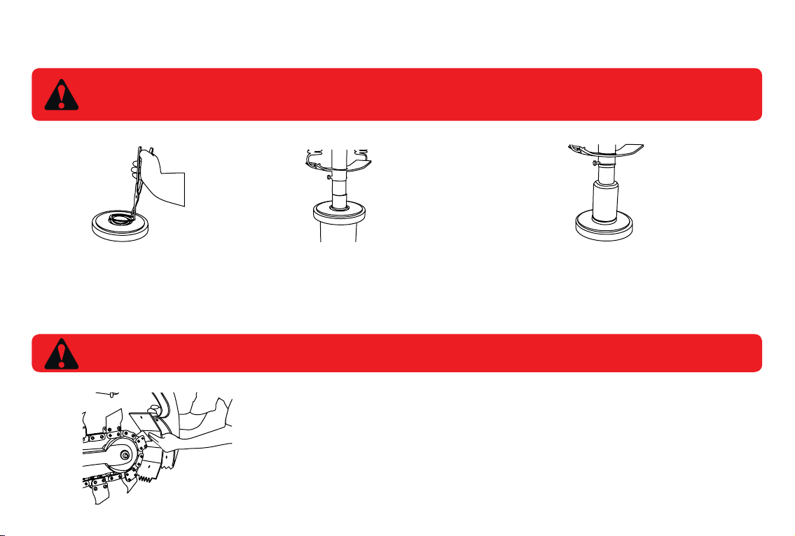
NOSE ROLLER BEARING REPLACEMENT
1. To replace the nose roller
bearing, rstly remove circlip
using a pair of straight circlip
pliers Fig 1.
2. Use a press to push the
bearing out ensuring the
pipe underneath is larger
than the bearing Fig 2.
FIG 1 FIG 2 FIG 3
SCRAPER SHOE REPLACEMENT
3. When pressing the new bearing in ensure the drift used is
the correct size. ie; The drift must sit against the outside shell of
the bearing being careful not to damage the ring that holds the
bearing together, make sure the bearing is sitting against the lip
on the opposite side of the nose roller and replace circlip.
NOTE: A HAMMER IS NOT RECOMMENDED FOR THIS PROCEDURE AS IT CAN DAMAGE THE
NEW BEARING.
SCRAPER SHOE
The Scraper shoe is designed to be interchangable should it get damaged or a different chain is tted
to the trencher. To replace simply remove the 3 nut and bolts holding it in place. Replace the shoe and
tighen the bolts using hand tools.
12 PM-000111-A Trencher: Service and Repair Manual - November 2014
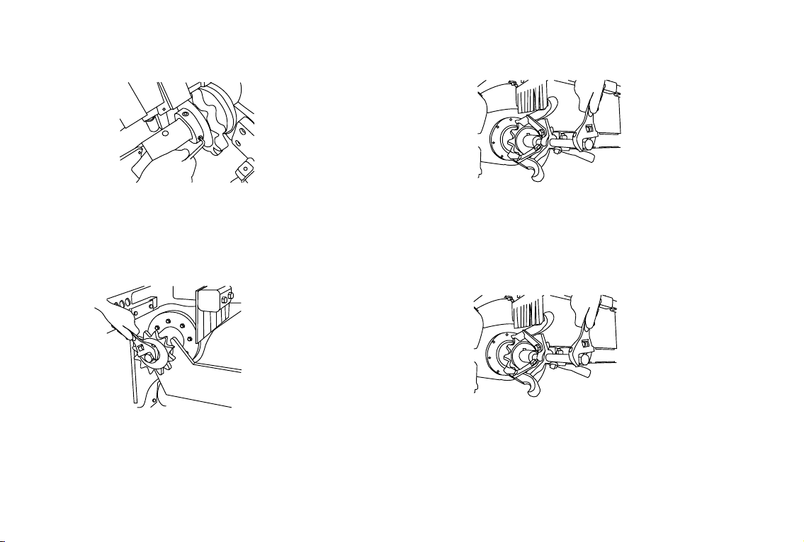
SPROCKET REPLACEMENT FOR BIGFOOT
SPROCKET REPLACEMENT FOR HYDRIVE
Firstly remove ½” bolt holding the auger, then remove auger.
Using a 3/16” Allen key loosen the 2 grub screws in the
retaining collar and slide collar off the shaft. (shown in Fig 1).
Firstly remove ½” bolt using a spanner, remove the
spocket washer and then slide sprocket off the shaft.
(shown in Fig 3).
Slide the sprocket off the shaft and replace with new sprocket. It is
recommended Anti-seize be applied to shaft before replacement of
sprocket (Shown in Fig 2)
Slide the sprocket off the shaft and replace with new sprocket. It is
recommended Anti-seize be applied to shaft before replacement of
sprocket (Shown in Fig 4)
FIG 1
FIG 3
FIG 2
FIG 4
MAINTENANCE

13
MAINTENANCE
BOOM ADJUSTMENT
IMPORTANT: SHUT DOWN TRENCHER & MACHINE BEFORE ANY ADJUSTMENTS ARE MADE
1. Use spanner supplied to
wind adjuster nut clockwise
for loosening, anti-clockwise
for tightening
1. The Trencher chain must rotate
in an anti-clockwise direction (when
viewed from the Motor side of the
Trencher). The Supply Line from the
Parent machine must be connected
to the ‘A’ port on the Trencher Motor
HYDRAULIC HOSE CONNECTION
NOTE: IF THE SPROCKET CANNOT BE REMOVED BY TAPPING WITH A HAMMER THEN A PULLER MAY HAVE TO BE USED.
SUPPLY FROM MACHINE
14 PM-000111-A Trencher: Service and Repair Manual - November 2014
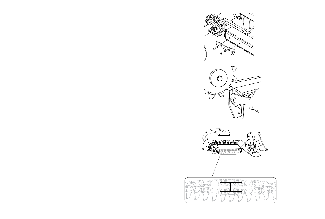
CHAIN ADJUSTMENT
1. To either adjust chain or remove chain – remove the ½" Bolts
holding spanner to outer boom. (FIG 1)
2. Use spanner supplied to wind adjuster nut clockwise for
loosening, anti clockwise for tightening. (FIG 2)
3. To achieve the correct chain tension: Adjust the tension on the lower
chain section at the midway point between the sprockets to allow 20mm
to 30mm of vertical movement. (FIG 3)
MAINTENANCE
Chain
midway point
between sprockets
20mm to 30mm
FIG 1
FIG 2
FIG 3

15
MAINTENANCE
SEAL REPLACEMENT
Before the seal can be replaced remove
retaining collar and sprocket as shown in
sprocket replacement. Then remove the
key and seal protector. Place a screwdriver
between outside of seal and inside of
housing. Tap gently with a hammer until
the seal can be levered out Fig 1. Inspect
the inside of the housing for damage and
if damaged or burred, clean up with emery
cloth.
Proceed to t the seal by using a large punch
and gently tap the seal into place ensuring
the seal is punched in evenly (see Fig 3).
This is very important as any misalignment
could cause damage to the seal and promote
a leak. The seal must be ush with the end
of the housing. Replace seal protector,
key, sprocket and retaining collar. Rell the
planetary with gear oil (See lubrication for
correct amount, grade of gear oil, and oil
lling procedures).
Before the seal can be replaced run
some grease around the inside lip of the
seal for lubrication to the shaft. Ensure
there are no burrs on the shaft between
the end of the shaft and the end of the
housing. File if necessary. Using loctite
243 (or equivalent) run a small bead
around the outside of the seal see
Fig 2.
FIG 2 FIG 3FIG 1
NOTE: MAKE SURE ALL GEAR OIL IS DRAINED AT THIS POINT.
AUGER ADJUSTMENT
1. The spoil removal auger has 2
settings. When a 150mm or 200mm
chain is being used the auger must
set closer to the chain. Use the bolt
hole which is closer to the auger
ights. The auger ights should be
atleast 100mm from the chain.
IMPORTANT
When a 250mm or 300mm chain is
being used it is important that the
Augers is set further away from the
chain. Use the bolt hole which is
further away from the auger ights.
The auger ights should be atleast
100mm from the chain.

16 PM-000111-A Trencher: Service and Repair Manual - November 2014
FITTING A TRENCHER CHAIN - MINI TRENCHER / BIGFOOT / BIGFOOT XD
MAINTENANCE
1. Start with the Trencher securely attached to a lifting device or
machine, ensure the adjustable boom is fully retracted.
2. Place Trencher on the ground, position chain in front of the
nose roller with cutting edge of the tooth facing away from the
Trencher. (Figure 1)
3. Lift chain onto Nose Roller (Figure 2) - A suitable lifting device
may need to be used for the larger heavier chains
4. Slide the chain along the boom and over the drive sprocket.
(Figure 3)
5. Raise the Trencher - Ensuring the Trencher is supported and
cannot fall whilst raised from the ground - Bring both ends of
the chain under the boom. (Figure 4)
6. Bring both ends of the chain together and insert the joining pin.
The joining pin must be inserted from the correct side which is
identied by looking at the head of the other link pins and
matching it to the same side. (Figure 5)
7. Tap the joining pin fully home using a soft head mallet. (Figure 6)
8. Insert the keeper pin and bend to secure. (Figure 7)
9. Adjust the chain tension and replace spanner to side of boom.
(Figure 8)
CAUTION: ALL WORK SAFE PRACTICES AND PROCEDURES MUST BE ADHERED TO AND APPROPRIATE PPE MUST BE WORN.
FIGURE 1
FIGURE 5
FIGURE 2 FIGURE 6
FIGURE 3
FIGURE 8
FIGURE 7

17
FITTING A TRENCHER CHAIN - HYDRIVE / HYDRIVE XD
MAINTENANCE
1. Start with the Trencher securely attached to a lifting device or
machine, ensure the adjustable boom is fully retracted.
2. Place Trencher on the ground, position chain in front of the
nose roller with cutting edge of the tooth facing away from the
Trencher. (Figure 1)
3. Lift chain onto Nose Roller (Figure 2) - A suitable lifting device
may need to be used for the larger heavier chains
4. Slide the chain along the boom and over the drive sprocket and
down past the idle sprocket. (Figure 3)
5. Raise the Trencher - Ensuring the Trencher is supported and
cannot fall whilst raised from the ground - Bring both ends of
the chain under the boom. (Figure 4)
6. Bring both ends of the chain together and insert the joining pin
The joining pin must be inserted from the correct side which is
identied by looking at the head of the other link pins and
matching it to the same side. (Figure 5)
7. Tap the joining pin fully home using a soft head mallet. (Figure 6)
8. Insert the keeper pin and bend to secure. (Figure 7)
9. Adjust the chain tension and replace spanner to side of boom.
(Figure 8)
CAUTION: ALL WORK SAFE PRACTICES AND PROCEDURES MUST BE ADHERED TO AND APPROPRIATE PPE MUST BE WORN.
FIGURE 1
FIGURE 2
FIGURE 3
FIGURE 4
FIGURE 5
FIGURE 6
FIGURE 8
FIGURE 7
18 PM-000111-A Trencher: Service and Repair Manual - November 2014
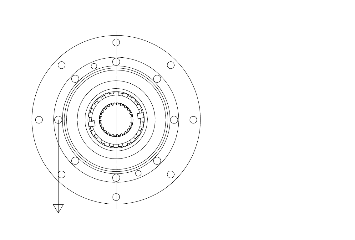
BEARING PRELOAD CHART
FORCE (in Kg)
This is the force to keep the housing spinning slowly
at a constant speed. The force required to start the
spinning initially will be greater. This is not the correct
reading. To ensure an accurate reading the force
direction must be held at 90 degrees. (As shown).
Reading is to be taken from the inner bolt pattern.
4 Kg
FORCE (in Kg)
This is the force to keep the housing spinning slowly at a constant speed.
The force required to start the spinning initially will be greater. This is not the correct reading.
To ensure an accurate reading the force direction must be held at 90 degrees. (As shown)
Reading is to be taken from the inner bolt pattern.
BEARING PRELOAD FORCE CHART
PD UNIT Housing Shaft DIA (mm) Force (Kg)
PDD,PDX,PDX2,PDX3
,PD3 - PD5 S2 50.8 4
PD6 - PD12 S4 70 7
S4 (RME) 70/75 10
S4 75 15
PD15 - PD22 S5 100 30
S6 100 30
PD25 - PD50 S8 120 35
S9.5 120 35
S10 150 45
S12 180 55
19
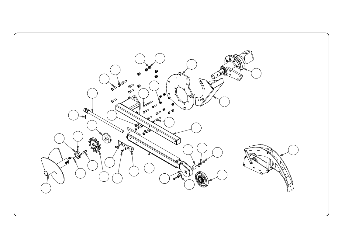
MINI BIGFOOT TRENCHER
SPARE PARTS
12
6
23
32
22
5
9
2
18
16
19
14
8
31
7
3
11
4
10
1
30
15
13
17
20
21
29
24
27
25
26
28

20 PM-000111-A Trencher: Service and Repair Manual - November 2014
REF NO. DESCRIPTION QTY ORDER CODE
1 BOLT HEX 1/2 X 1 G8 UNC ZINC PLATED 2 FA-000026
2 BOLT HEX 1/2 X 2.1/2 G8 UNC ZINC PLATED 3 FA-000027
3 BOLT HEX 1/2 X 2 G8 UNC ZINC PLATED 5 FA-000029
4 BOLT HEX 1/2 X 3.1/2 G8 UNC ZINC PLATED 1 FA-000030
5 BOLT HEX 3/8 X 3/4 G8 UNC ZINC PLATED 2 FA-000052
6 BOLT HEX 5/8 X 2 G8 UNC ZINC PLATED 5 FA-000073
7 NUT NYLOC 1/2" ZINC PLATED 9 FA-000090
8 NUT NYLOC 5/8 UNC GR5 ZP 8 FA-000095
9 SCREW SOCKET HEAD CAP 5/8 X 1 3/4" UNC ZINC PLATED 4 FA-000123
10 BOLT HEX 5/8 X 2.1/4 G8 UNC ZINC PLATED 1 FA-000186
11 SCREW SOCKET SET 3/8 IN X 3/8 IN UNC 2 FA-000400
12 GEARBOX ASSEMBLY - BIGFOOT OED TRENCHER - 21 GF 1 GB-002297
13 SPRING PIN 1/4" X 1.1/2" 1 SP-000007
14 SEAL PROTECTOR - BIGFOOT TRENCHER 1 TR-000025
15 NOSE ROLLER PIN WASHER - TRENCHER COMMON PARTS 2 TR-000026
16 KEY STEEL 1/2" SQ X 60 LG 1 TR-000027
17 NOSE ROLLER SQUARE PIN - TRENCHER COMMON PARTS 1 TR-000029
18 DRIVE SPROCKET COLLAR - TRENCHER COMMON PARTS 1 TR-000031
19 DRIVE SPROCKET 1.5/8" PITCH 12 TOOTH - TRENCHER COMMON PARTS 1 TR-000035
20 BOOM ADJUSTER ROD 1" UNC 1 TR-000062
MINI BIGFOOT TRENCHER - PARTS LIST
SPARE PARTS
This manual suits for next models
4
Table of contents
Other Digga Farm Equipment manuals


