TMG TMG-TRC48 User manual

PRODUCT MANUAL
v.2023.4.19
3-POINT HITCH
ROTARY CUTTER
TMG- TRC 48 / 60
tttttTFM60/TFM68/
TFM72TFM60/TFM68/
TFM72

www.tmgindustrial.com 2 / 22 TOLL FREE: 1-877-761-2819
CONTENTS
IMPORTANT SAFETY INFORMATION ............................................................................................................... 3
Safety always .............................................................................................................................................................................................3
Transport machinery safely.......................................................................................................................................................................4
Safety Labels..............................................................................................................................................................................................4
INTRODUCTION.................................................................................................................................................. 5
Using This Manual......................................................................................................................................................................................5
Terminology................................................................................................................................................................................................5
Owner Assistance ......................................................................................................................................................................................5
SECTION 1: ASSEMBLY AND SET-UP ............................................................................................................... 6
Tractor Requirements ................................................................................................................................................................................6
Packing Description...................................................................................................................................................................................6
Packing List ................................................................................................................................................................................................7
Installation Wizard .....................................................................................................................................................................................9
Tractor Hook-Up.......................................................................................................................................................................................12
Driveline Installation.................................................................................................................................................................................12
SECTION 2: OPERATING INSTRUCTIONS.......................................................................................................13
Transporting .............................................................................................................................................................................................13
Mowing Instructions ................................................................................................................................................................................13
Operating Instructions .............................................................................................................................................................................13
SECTION 3: ADJUSTMENTS............................................................................................................................14
Leveling the Rotary cutter........................................................................................................................................................................14
Cutting Height Adjustment......................................................................................................................................................................14
3-Point Hitch Adjustments ......................................................................................................................................................................14
Belt Tension..............................................................................................................................................................................................14
SECTION 4: MAINTENANCE AND LUBRICATION...........................................................................................14
Maintenance.............................................................................................................................................................................................14
Knife Replacement...................................................................................................................................................................................14
Storage......................................................................................................................................................................................................15
Lubrication................................................................................................................................................................................................15
SECTION 5: SPECIFICATIONS & CAPACITIES ................................................................................................15
SECTION 6: TROUBLESHOOTING....................................................................................................................16
SECTION 7: APPENDIX.....................................................................................................................................17
Warranty....................................................................................................................................................................................................17
Bolt Torque ...............................................................................................................................................................................................17
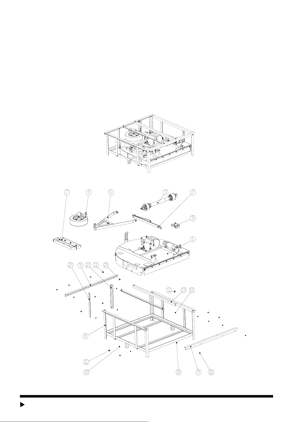
PART BREAKDOWN LIST .................................................................................................................................19

www.tmgindustrial.com 3 / 22 TOLL FREE: 1-877-761-2819
IMPORTANT SAFETY INFORMATION
Safety always
Thoroughly read and understand the instructions given in this manual before operation. Refer to the “Safety Decal”, read all
instructions noted on them.
Do not allow anyone to operate this equipment who has not fully read and comprehended this manual and who has not been
properly trained in the safe operation of the equipment.
1. Operator should be familiar with all functions of the unit. Operate implement from the driver’s seat only.
2. Make sure all guards and shields are in place and secured before operating the implement.
3. Do not leave tractor or implement unattended with engine running.
4. Dismounting from a moving tractor could cause serious injury or death.
5. Do not stand between tractor and implement during hitching.
6. Keep hands, feet, and clothing away from power-driven parts.
7. Wear snug fitting clothing to avoid entanglement with moving parts.
8. Watch out for wires, trees, etc., when raising implement. Make sure all persons are clear of working area.
9. Turning tractor too tight may cause implement to ride up on wheels. This could result in injury or equipment damage.
Look For the Safety Alert Symbol
The SAFETY ALERT SYMBOL indicates there is a potential hazard to personal safety involved and extra safety precaution
must be taken. When you see this symbol, be alert and carefully readthe message that follows it. In addition to design and
configuration of equipment, hazard controland accident prevention are dependent upon the awareness, concern,
prudence, and proper training of personnel involved in the operation, transport, maintenance and storage of equipment.
Be aware of signal words
A signal word designates a degree or level of hazard seriousness. The signal words are:
DANGER
Indicates an imminently hazardous situation which, if not avoids, will result in death or serious injury. This signal word is limited to
the most extreme situations, typically for machine components that, for functional purpose, cannot be guarded.
WARNING
Indicates a potentially hazardous situation which, if not avoided, could result in death or serious injury, and includes hazards that
are exposed when guards are removed. It may also be used to alert against unsafe practices.
CAUTION
Indicates a potentially hazardous situation which, if not avoided, may result in minor or moderate injury. It may also be used to
alert against unsafe practices.
For you protection
Thoroughly read and understand the “safety label” section, read all instructions noted on them.
Shut down and storage
Lower machine to ground, put tractor in park, turn off engine, and remove the ignition key.
Detach and store implements in a area where children normally do not play. Secure implement by using blocks and supports.
Use safety lights and devices
Slow moving tractors, self-propelled equipment, and towed implements can create a hazard when driven on public roads. They
are difficult to see, especially at night.
Flashing warning lights and turn signals are recommended whenever driving on public roads. Use lights and devices provided
with implement.

www.tmgindustrial.com 4 / 22 TOLL FREE: 1-877-761-2819
Transport machinery safely
1. Comply with state and local laws.
2. Maximum transport speed for implement is 20 mph. Do not exceed. Never travel at a speed which does not allow adequate
control of steering and stopping. Some rough terrain require a slower speed.
3. Sudden braking can cause a towed load to swerve and upset. Reduce speed if towed load is not equipped with brakes.
4. Use the following maximum speed - tow load weight ratios as a guideline:
5. 20 mph when weight is less than or equal to the weight of tractor.
6. 10 mph when weight is double the weight of tractor.
7. IMPORTANT: Do not tow a load that is more than double the weight of tractor.
Keep riders off machinery
1. Riders obstruct of operator’s view, they could be struck by foreign objects or thrown from the machine.
2. Never allow children to operate equipment.
Practice safe maintenance
1. Understand procedure before doing work. Use proper tools and equipment. refer to Operator’s Manual for additional
information.
2. Work in a clean dry area.
3. Lower the implement to the ground, put tractor in park, turn off engine, and remove key before performing maintenance.
4. Allow implement to cool completely.
5. Do not grease or oil implement while it is operation.
6. Inspect all parts. Make sure parts are in good condition and installed properly.
7. Remove buildup of grease, oil or debris.
8. Remove all tools and unused parts from implement before operation.
Prepare for emergencies
1. Be prepared if a fire starts.
2. Keep a fist aid kit and fire extinguisher handy.
3. Keep emergency numbers for doctor, ambulance, hospital and fire department near phone.
Wear protective equipment
1. Protective clothing and equipment should be worn.
2. Wear clothing and equipment appropriate for the job. Avoid loose fitting clothing.
3. Prolonged exposure to loud noise can cause hearing impairment or hearing loss. Wear suitable hearing protection such as
earmuffs or earplugs.
4. Operating equipment safely requires the full attention of the operator. Avoid wearing radio headphones while operating
machinery.
Avoid high pressure fluids hazard
1. Escaping fluid under pressure can penetrate the skin causing serious injury.
2. Avoid the hazard by relieving pressure before disconnecting hydraulic lines.
3. Use a piece of paper or cardboard, not body parts, to check for suspected leaks. Wear protective gloves and safety
glasses or goggles when working with hydraulic systems.
4. If an accident occurs, see a doctor immediately. Any fluid injected into the skin must be treated within a few hours or
gangrene may result.
Safety Labels
Your Rotary Cutter comes equipped with all safety labels in place. They were designed to help you safely operate your
implement. Read and follow their directions.
1. Keep all safety labels clean and legible.
2. Replace all damaged or missing labels. To order new labels go to your nearest TMG dealer or visit our dealer locator at
TMG.com.

www.tmgindustrial.com 5 / 22 TOLL FREE: 1-877-761-2819
3. Some new equipment installed during repair requires safety labels to be affixed to the replaced component as specified
by TMG. When ordering new components make sure the correct safety labels are included in the request.
4. Refer to this section for proper label placement. To install new labels:
a. Clean the area the label is to be placed.
b. Spray soapy water on the surface where the label is to be placed.
c. Peel backing from label. Press firmly onto the surface.
d. Squeeze out air bubbles with the edge of a credit card.
Safety labels
Introduction
TMG welcomes you to the growing family of new product owners. This implement has been designed with care and built by
skilled workers using quality materials. Proper assembly, maintenance, and safe operating practices will help you get years of
satisfactory use from the machine.
The Rotary cutters are designed for Category 1 - three point hitch or Quick-Hitch System mounting. These Fixed Bar Rotary
Cutters are ideal for ripping, leveling, finish grading, and backfilling applications at feedlots, outdoor arenas, building sites, and
maintenance operations on farm and ranch lanes or roadways.
Using This Manual
1. This Operator’s Manual is designed to help familiarize you with safety, assembly, operation, adjustments, troubleshooting,
and maintenance. Read this manual and follow the recommendations to help ensure safe and efficient operation.
2. The information contained within this manual was current at the time of printing. Some parts may change slightly to
assure you of the best performance.
3. To order a new Operator’s or Parts Manual contact your authorized dealer. Manuals can also be printed from the TMG
Service & Support Center by your dealer.
Terminology
“Right” or “Left” as used in this manual is determined by facing the direction the machine will operate while in use unless
otherwise stated.
Note: A special point of information that the operator must be aware of before continuing.
Important: A special point of information related to its preceding topic. The intention is that this information should be read and
noted before continuing.
Owner Assistance
The Warranty Registration card should be filled out by the dealer at the time of purchase. This information is necessary to
provide you with quality customer service. If customer service or repair parts are required contact a dealer. A dealer has trained
personnel, repair parts and equipment needed to service the machine.
The parts on your machine have been specially designed and should only be replaced with genuine parts.
Serial Number Plate
For prompt service always use the serial number and model number when ordering parts from your dealer. Be sure to include
your serial and model numbers in correspondence also.

www.tmgindustrial.com 6 / 22 TOLL FREE: 1-877-761-2819
Section 1: Assembly and Set-up
Tractor Requirements
Tractor horsepower should be within the range noted below. Tractors outside the horsepower range must not be used. Must be
using a minimum of 40 hp when operating at maximum capability. The lower 3-Point arms must be stabilized to prevent side to
side movement. Most tractors have sway blocks or adjustable chains for this purpose.
Required Horsepower Range . . . . . . . . . 20 to 60 hp (min 40 PTO hp for max. capacity)
Power Take-off Maximum . . . . . . . . . . . . . . . . . . . . . . . . . . . . . . . . . . . . . . . . . 540 rpm
Spline Shaft Requirement . . . . . . . . . . . . . . . . . . . . . . . . . . . . . . . . . . .1 3/8” – 6 Spline
Hitch Type . . . . . . . . . . . . . . . . . . . . . . . . . . . . . . . . . . . . . .3-Point Cat 1 or Quick-hitch
Packing Description
Remove any loose parts or packaging from the crate. Check goods without damage and omission.
FIGURE 1: Your New Standard Rotary Cutter as It Is Shipped to You
FIGURE 2: The Standard Rotary cutter and Accessory in Package

www.tmgindustrial.com 7 / 22 TOLL FREE: 1-877-761-2819
Packing List
The detailed packing list as the following table.
Item
Description
Qty.
Package Form
1
Main body of the Rotary Cutter
1
None
2
Front and rear braces
1
Bubble film
3
Driveline shaft with clutch
1
Bubble film
4
Wheel tire assembly and fittings
1
Bubble film
5
Pivoting upper hitch-black and
fittings
1
Bubble film
6
Tailwheel adjusting bracket and
fittings
1
Bubble film
7
R&L Skid weldment and fittings
1
Bubble film
8
Iron crate
1
None
9
Removable angle steel
2
Crate attachment
10
Locknut M10
16
Crate attachment
11
Bolt M10x25
16
Crate attachment
12
Removable angle steel support
2
Crate attachment
13
Top bracing
2
Crate attachment
The detailed description of front and rear braces
FIGURE 3: Front and Rear Braces
Item
Description
Qty.
1
Rear brace
2
2
Front brace
2
The detailed description of wheel tire assembly and fittings
FIGURE 4: Wheel Tire Assembly and Fittings
Item
Description
Qty.
1
Rubber tire assembly
1
2
Spacer H=6
1
3
Cap shaft mount
1
4
Safety lock pin φ8x45
1
The detailed description of pivoting upper hitch-black and fittings

www.tmgindustrial.com 8 / 22 TOLL FREE: 1-877-761-2819
FIGURE 5: Pivoting Upper Hitch-Black and Fittings
Item
Description
Qty.
1
Safety lock pin φ11x50
1
2
Hitch pin - upper
1
3
Pivoting upper hitch-black
1
4
Plain washer 16
2
5
Bolt M16x110
1
6
Spacer
2
7
Locknut M16
1
The detailed description of tailwheel adjusting bracket and fittings
FIGURE 6: Tailwheel Adjusting Bracket and Fittings
Item
Description
Qty.
1
Locknut M16
2
2
Plain washer 16
4
3
Bolt M16x55
2
4
Gauge wheel mainframe weldment
1
5
Plain washer 12
4
6
Bolt M12x40
2
7
Locknut M12
2
The detailed description of R&L skid weldment and fittings

www.tmgindustrial.com 9 / 22 TOLL FREE: 1-877-761-2819
FIGURE 7: R&L skid weldment and fittings
Item
Description
Qty.
1
Skid weldment - R
1
2
RHSNB M10x25 GR10.9
8
3
Plain washer 10
8
4
Locknut M10
8
5
Skid weldment - L
1
Installation Wizard
The installation wizard will guide you to finish the final assembly of your new rotary cutter easily.
1. Tool Required
1/2” Ratchet Wrench with 13mm,16mm,24mm sleeves
17-19,22-24Spanner
Safety Goggles and Gloves Installation
2. Installation
Cut all zip ties and disassemble shipping crate.
Step1: Installing front & rear braces, pivoting upper hitch-black, tailwheel adjusting bracket and fittings
Remove the packaging of front & Rear braces, pivoting upper hitch-black, tailwheel adjusting bracket and fittings.
Installing front & rear braces, pivoting upper hitch-black, tailwheel adjusting bracket and fittings onto main body of the rotary
cutter according to the figure 8.
Tighten item 7, item 17 completely. Tighten item10 but make sure item6 & item13 can rotate freely.

www.tmgindustrial.com 10 / 22 TOLL FREE: 1-877-761-2819
FIGURE 8: Installing Braces, Pivoting Upper Hitch-Black, Tailwheel Adjusting Bracket and Fittings
Item1 – Main body of the rotary cutter Item2 – Front brace (2pcs)
Item3 – Rear brace (2pcs) Item4 – Plain washer16 (6pcs) Item5 – Bolt M16x55 (2pcs)
Item6 – Gauge wheel mainframe weldment (1 set) Item7 – Locknut M12 (2pcs)
Item8 – Plain washer 12 (4pcs) Item9 – Bolt M12x40 (2pcs) Item10 – Locknut M16 (3pcs)
Item11 – Bolt M16x110 (1pcs) Item12 – Spacer (2pcs)
Item13 – Pivoting upper hitch-black (1pcs) Item14 – Hitch pin lower (2pcs)
Item15 – Plain washer 22 (2pcs) Item16 – Spring washer 22 (2pcs)
Item17 – Hex. Nut M16 (2pcs)
Step2: Installing R&L skid weldment and fittings
Remove the packaging of R&L skid weldment and fittings.
Align lower link arms of tractor to hitch lower hitch pins into lower ball swivels. Attach with safety lock pin.
Raise rotary cutter from the ground. Install R&L skid weldment onto the rotary cutter.
Tighten locknuts completely.

www.tmgindustrial.com 11 / 22 TOLL FREE: 1-877-761-2819
FIGURE 9: Installing R&L Skid Weldment and Fittings
Item1 – RHSNB M10x25 GR10.9 (8pcs) Item2 – Skid weldment – L (1pcs)
Item3 – Plain washer 10 (8pcs) Item4 – Locknut M10 (8pcs)
Item5 – Main body of the rotary cutter Item6 – Skid weldment – R (1pcs)
Step3: Installing wheel tire assembly and fittings
Remove the packaging of wheel tire assembly and fittings.
Remove item4, item5 and one piece of item3 from wheel tire assembly. Insert the pivot shaft of wheel tire assembly into the
bushing of the gauge wheel mainframe weldment and reinstall item4 to item5. Secure with item3.
FIGURE 10: Installing Wheel Tire Assembly and Fittings
Item1 –Main body of the rotary cutter Item2 – Wheel tire assembly – (1 set)
Item3 – Spacer H=6 (1pcs) Item4 – Cap shaft mount (1pcs)
Item5 –Safety lock pin φ8x45 (1 pcs)

www.tmgindustrial.com 12 / 22 TOLL FREE: 1-877-761-2819
WARNING
SAE EP 90W Gear oil must be filled before you finish final assembly and start your first use.
Overfilling or under filling gear oil may cause gearbox seizing or damage.
Step4: Gear oil filling
Check oil level in gearbox by removing the cap located on the side of the gearbox. Oil should be level with middle side of plug
hole. Add oil necessary by removing top cap and side plug. Add oil until it flows from middle side plug hole.
FIGURE 11: Gearbox construction
Item1 – Cap for inlet gearbox oil
Item2 – gearbox
Item3 – Plug for gearbox oil level
Tractor Hook-Up
1. Be certain that tractor draw bar will not interfere. Move draw bar ahead or remove if required. Draw bar should also be
checked for clearance when unit is being raised for the first time.
2. Align lower link arms of tractor to hitch clevises on rotary cutter. Insert lower hitch pins into lower ball swivels and attach
link pins.
3. Attach tractor top link to upper floating hitch on rotary cutter with pin supplied. Secure with lock pin.
4. Adjust tractor top link in or out to place upper hitch pin vertically above or slightly behind lower hitch pins to allow rotary
cutter flotation. The rotary cutter should be run with the back 15 degrees lower than the front.
Driveline Installation
1. Slide driveline end with extended safety cone over spline shaft of gearbox and secure with attaching device.
2. Slide driveline over tractor’s spline PTO shaft and secure with locking device of driveline.
3. Driveline should now be moved back and forth to ensure that it is secure on the PTO shaft of the tractor and rotary cutter
gearbox.
4. Attach chain from the driveline shield to one of the upper hitch braces to ensure that the shield does not rotate.
5. Should driveline require shortening:
a. Hold the half-shafts next to each other in the shortest working position andmark them.
b. Shorten inner and outer guard tubes equally.
c. Shorten inner and outer sliding profiles by the same length as the guard tubes.
d. Proper overlap is a minimum of one-half the length of each tube, with both tubes being of equallength.
e. Round off all sharp edges and remove burrs. Grease sliding profiles.
CAUTION
Tractor PTO shield and all rotary cutter guards must be always in place during operation!

www.tmgindustrial.com 13 / 22 TOLL FREE: 1-877-761-2819
Section 2: Operating Instructions
Transporting
NOTE: Always disengage PTO before raising rotary cutter to transport position.
1. When raising the rotary cutter to transport position, be sure that driveline does not contact tractor or rotary cutter. Adjust
and set the tractor’s 3-point hitch lift height so that the driveline does not contact rotary cutter deck in the fully raised
position.
2. Be sure to reduce tractor ground speed when turning, leaving enough clearance so that the rotary cutter does not contact
obstacles such as buildings, trees or fences.
3. Select a safe ground travel speed when transporting from one area to another. When traveling on roadways, transport in
such a way that faster moving vehicles may pass safely.
4. When traveling over rough or hilly terrain, shift tractor to a lower gear.
CAUTION
When traveling on public roads, whether at night or during the day, use accessory lights and devices foradequate warning to
operators of other vehicles. Comply with all Federal, State, and local laws.
Mowing Instructions
1. Clear area to be mowed of objects and debris that might be picked up and thrown by the rotary cutter blades.
2. Grass is best cut when it is dry. Mowing wet grass can cause plugging resulting in grass clumps behind the rotary cutter.
3. Grass should be mowed frequently as shorter clippings deteriorate faster.
4. If mowing extremely tall grass, it is best to raise cutting height and mow the area, then lower cutting height and mow a
second time at the desired height.
Operating Instructions
Proper servicing and adjustments are the key to the long life of any machine. With careful and systematic inspection of the rotary
cutter, costly maintenance, time and repair can be avoided.
Before beginning to mow, the following inspection should be performed:
1. Check oil level in gearbox.
2. Check that all plugs in gearbox have been replaced and tightened properly.
3. Be sure all rotary cutter knives, bolts and nuts are tight.
4. Be certain all guards and shields are in place and secure.
5. Grease driveline shaft and all other grease fittings.
6. Clear area to be mowed of rocks, branches and other foreign objects.
7. Lower rotary cutter to ground. Set tractor throttle at approximately 1/4 open. Engage PTO to start blades rotating.
8. Operate with 540 rpm PTO tractor.
9. At first begin mowing at a slow forward speed and shift up until the desired speed is achieved - maintaining 540 PTO rpm.
10. Rotary cutter knives will cut better at a faster blade speed than at reduced throttle.
11. After mowing the first 50 feet, stop and check to see that the rotary cutter is adjusted properly.
12. Do not make sharp turns or attempt to back up while rotary cutter is on the ground.
13. Do not engage PTO with rotary cutter in the fully raised position. Do not engage PTO at full throttle.

www.tmgindustrial.com 14 / 22 TOLL FREE: 1-877-761-2819
Section 3: Adjustments
Leveling the Rotary cutter
NOTE: Tractor and rotary cutter should be on level ground.
Leveling can be adjusted at the tractor’s 3-point arms and center link.
Cutting Height Adjustment
The machines cutting height depends upon the position of the rear roller.
1. Remove the bolts that fix the roller on both sides.
2. Lift or lower both sides of roller in equal measurements.
3. Replace bolts and re-tighten.
3-Point Hitch Adjustments
The 3-point hitch system on this rotary cutter has been designed for front to back flotation when mowing on uneven terrain. Adjust
tractor’s top center link to place the upper hitch pin vertically above or slightly behind the lower hitch pins. The rotary cutter should be
run with the back 15 degrees lower than the front.
The hitch can also be adjusted from side to side by turning the adjustment handle. Turn handle until you have achieved your desired
location.
CAUTION
Engage parking brake, shut off tractor, remove key and disengage PTO before making any heightadjustments!
Belt Tension
CAUTION
Belt drive system under spring tension; use care to avoid bodily harm!
The Belt tension should be checked after the first 20 hours of use. And then every 40 hours of use.
1. Tension on the belt can be adjusted with the belt tension bolt. Turn the bolt until desired tension is achieved. When the
belt has the correct tension the gearbox should be adjusted so that the gearbox extension is running straight (parallel)
with the Rotary Cutter. Loosen bolts at the bottom of the gearbox and move gearbox until gearbox extension is running
straight.
2. Excessive tension on the belt may lead to premature failure of belt and drive components.
CAUTION
Excessive tension on the belt may lead to premature failure of belt and drive components. Excessivetension on the belt
may also lead to a safety hazard to the operator or bystanders.
Section 4: Maintenance and Lubrication
Maintenance
Proper servicing and adjustment is the key to the long life of any farm implement. With careful and systematic inspection, you can
avoid costly maintenance, time and repair.
CAUTION
For safety reasons, each maintenance operation must be performed with tractor PTO disengaged,rotary cutter lowered
completely to ground and tractor engine shut off with ignition key removed.
1. After using the rotary cutter for several hours, check all bolts to be sure they are tight and check drive belt tension.
2. Replace any worn, damaged or illegible safety decals by obtaining new decals from dealer.
Knife Replacement

www.tmgindustrial.com 15 / 22 TOLL FREE: 1-877-761-2819
IMPORTANT:Make sure that the knife is the same length as the others on the rotary cutter. This will keep the rotor rotation
balanced.
1. Remove bolt and nut.
2. Remove old knife.
3. Install new knife and existing bolt.
4. Secure with nut.
Storage
At the end of the working season or when the rotary cutter will not be used for a long period, it is good practice to clean off any dirt or
grease that may have accumulated on the rotary cutter and any of moving parts.
1. Clean as necessary.
2. Check knives for wear and replace if necessary.
3. Inspect rotary cutter for loose, damaged or worn parts and adjust or replace as needed.
4. Store unit inside if possible for longer life.
5. Repaint parts where paint is worn or scratched to prevent rust.
6. Replace all damaged or missing decals.
Lubrication
Driveline Shaft U-Joints
Type of Lubrication: Multi-purpose Grease
Roller Bearing (Both Ends)
Type of Lubrication: Multi-purpose Grease
Cutter Rotor Bearing (Both Ends)
Type of Lubrication: Multi-purpose Grease
Gearbox
Type of Lubrication: SAE 90W Gear Lube
Check oil level in gearbox by removing the plug located on the right-hand side. Oil should be level with bottom of plug hole. Add oil if
necessary, by removing top fill plug and side plug. Add oil until it flows from side plug hole.
Do not overfill!
IMPORTANT: Rotary cutter should be level when checking oil in gearbox!
Driveline Profiles
Type of Lubrication: Multi-purpose Grease
Section 5: Specifications & Capacities
Model
TMG-TRC48
TMG-TRC60
Working Width
48” / 1219
60” / 1524
Overall With
53” / 1347
65” / 1652
Overall Length
79.2” / 2012.5
91.2” / 2317.5
Cutting Height
1.5”-11”
1.5”-11”
Net Weight
440lb / 200kg
518lb / 235kg
Cutting Capacity
1” Diameter
1” Diameter

www.tmgindustrial.com 16 / 22 TOLL FREE: 1-877-761-2819
Section 6: Troubleshooting
Problem
Cause
Solution
Oil seal leaking
Gearbox overfilled
Drain to side plug hole
Seals damaged
Replace seals
Grass or wire wrapped on shaft in seal area
Check seal areas daily
Driveline yoke or cross failing
Shock load
Avoid hitting solid objects
Needs lubrication
Lubricate every 8 hours
Driveline clutch is slipping
Scalping the ground
Raise cutting height
Cutting too fast
Reduce travel speed
Power take-off being engaged too fast at
high engine rpm
Slowly engage power take-off at low engine
rpm
Cutting over solid objects
Avoid solid objects
Clutch spring not set correctly
Check dimension for spring setting on clutch
Bent Driveline ( NOTE: driveline
should be repaired or replaced if
bent)
Contacting frame
Reduce lift height in transport position
Contacting drawbar
Reposition drawbar
Bottoming out
Shorten driveline
Driveline telescoping tube failing
Needs lubrication
Lubricate every 20 hours
Shock load
Avoid hitting solid objects
Driveline telescoping tube
wearing
Needs lubrication
Lubricate every 20 hours
Blades wearing excessively
Cutting on sandy ground
Raise cutting height
Contacting ground frequently
Raise cutting height
Blade breaking
Hitting solid objects
Avoid hitting solid objects
Blades coming loose
Blade not tighten property
Tighten blade hardware (refer to “Cutting
Blade Maintenance” .
Not using new locknut when replacing blades
Use new locknuts.
Blade carrier become loose
Running loose in the past
Replace gearbox output shaft and blade carrier
Blade carrier hardware not tight enough
Tighten to specified torque
Blade bolt holes worn
Blade hardware running loose
Replace blades, blade bolts, and locknut if
worn
Blade carrier bent
Hitting solid objects
Avoid hitting solid objects and replace blade
carrier
Excessive side skid wear
Cutting height not level
Adjust cutter height
Soil abrasive
Adjust cutter height
Cutting too low
Adjust cutter height
Tail wheel support failing
Lowering too fast
Adjust rate of drop

www.tmgindustrial.com 17 / 22 TOLL FREE: 1-877-761-2819
Hitting objects when turning
Reduce speed on turns
Excessive vibration
Driveline bent
Replace driveline
Blades loose
Tighten blade bolts
Blade carrier bent
Replace blade carrier
Blade broken
Replace blade
Blade will not swing
Remove and inspect blade
Blades have unequal weight
Replace both blades
Dishpan bent
Replace dishpan
Section 7: Appendix
Warranty
TMG warrants to the original purchaser that this product will be free from defects in material and workmanship beginning on
the date of purchase by the end user according to the following schedule when used as intended and under normal service and
conditions for personal use.
Overall Unit and Driveline: One-year.
Blades and Belts: Considered wear items.
This warranty is limited to the replacement of any defective part by manufacturer and the installation by the dealer of any such
replacement part, and does not cover common wear items such as blades, belts, tines, etc. TMG reserves the right to inspect
any equipment or parts which are claimed to have been defective in material or workmanship.
This warranty does not apply to any part or product which in TMG’s judgment shall have been misused or damaged by accident
or lack of normal maintenance or care, or which has been repaired or altered in a way which adversely affects its performance
or reliability, or which has been used for a purpose for which the product not designed. Misuse also specifically includes failure
to properly maintain oil levels, grease points, and driveline shafts.
Claims under this warranty must be made to the dealer which originally sold the product and all warranty adjustments must be
made through such dealer. TMG reserves the right to make changes in materials or design of the product at any time without
notices.
This warranty shall not be interpreted to render TMG liable for damages of any kind, direct, consequential, or contingent to
property. Furthermore, TMG shall not be liable for damages resulting from any cause beyond its reasonable control. This
warranty does not extend to loss of crops, any expense or loss for labor, supplies, rental machinery or for any other reason.
No other warranty of any kind whatsoever, express or implied, is made with respect to this sale; and all implied warranties of
merchantability and fitness for a particular purpose which exceed the obligations set forth in this written warranty are hereby
disclaimed and excluded from this sale.
Bolt Torque
The tables shown below give correct torque values for various bolts and cap screws. Tighten all bolts to the torques specified
unless otherwise noted. Check tightness of bolts periodically, using bolt torque chart as a guide. Replace hardware with the
same strength bolt.
ENGLISH TORQUE SPECIFICATIONS

www.tmgindustrial.com 18 / 22 TOLL FREE: 1-877-761-2819
Bolt Diameter
Bolt Torque
SAE 2
N.m lb-ft
SAE 5
N.m lb-ft
SAE 8
N.m lb-ft
1/4”
8
6
12
9
17
12
5/16”
13
10
25
19
36
27
3/8”
27
20
45
33
63
45
7/16”
41
30
72
53
100
75
1/2”
61
45
110
80
155
115
9/16”
95
60
155
115
200
165
5/8”
128
95
215
160
305
220
3/4”
225
165
390
290
540
400
7/8”
230
170
570
420
880
650
METRIC TORQUE SPECIFICATIONS
Bolt Diameter
Bolt Torque
8.8
N.m lb-ft
10.9
N.m lb-ft
M3
0.5
0.4
1.8
1.3
M4
3
2.2
4.5
3.3
M5
6
4
9
7
M6
10
7
15
11
M8
25
18
35
26
M10
50
37
70
52
M12
90
66
125
92
M14
140
103
200
148
M16
225
166
310
229
M20
435
321
610
450
M24
750
553
1050
744
M30
1495
1103
2100
1550
M36
2600
1917
3675
2710
Torque figures indicated above are valid for non-greased or non-oiled threads and heads otherwise specified. Therefore, do not
grease or oil bolts or cap screws unless otherwise specified in this manual. When using locking elements, increase torque
values by 5%.

www.tmgindustrial.com 19 / 22 TOLL FREE: 1-877-761-2819
Part Breakdown List
TMG-TRC48/TMG-TRC60 Part Breakdown
PART NO.
REF. NO.
PART DESCRIPTION
QTY.
REMARK
1
4030100344
Cutter Deck
1
TMG-TRC48
4030100345
1
TMG-TRC60
2
4040100018
Gearbox 40HP
1
3
7040100008
Plain washer 16x30x3
14
4
7040400008
Spring washer
4
5
7030100008
Hex. Nut M16
4
6
7010100037
Bolt M16x55
6

www.tmgindustrial.com 20 / 22 TOLL FREE: 1-877-761-2819
7
4010000183
PTO guard mount
1
8
7040100004
Plain washer 8x16x1.6
12
9
7040400004
Spring washer 8
4
10
7010100006
Bolt M8x20
8
11
4010000165
PTO guard
1
12
7030500016
Locknut M8
4
13
4030100347
Skid weldment - R
1
TMG-TRC48
4030100351
1
TMG-TRC60
14
7010400004
RHSNB M10x25 GR10.9
8
15
7040100005
Plain washer 10x20x2
34
TMG-TRC48
36
TMG-TRC60
16
7030500017
Locknut M10
21
TMG-TRC48
22
TMG-TRC60
17
4030100346
Skid weldment - L
1
TMG-TRC48
4030100350
1
TMG-TRC60
18
BCL120.00.00.001
Front rubber guard
1
TMG-TRC48
BCL150.00.00.001
1
TMG-TRC60
19
7010100013
Bolt M10x25
13
TMG-TRC48
14
TMG-TRC60
20
4020000001
Hitch pin - Lower
2
21
7040200010
Plain washer 22x39x3
2
22
7040400010
Spring washer 22
2
23
7030100010
Hex. Nut M22
2
24
4300100004
Safety lock pin φ11x50
3
25
4010000184
Front brace
2
26
4010000185
Rear brace
2
TMG-TRC48
4010000188
2
TMG-TRC60
27
7030500020
Locknut M16
3
28
4020000193
Spacer
2
29
4010000144
Pivoting upper hitch - black
1
30
7010200010
Bolt M16x110
1
31
4020000017
Hitch pin - Upper
1
32
4100200027
Access rubber cover φ91.3
1
33
BCL120.00.00.008
Rear rubber guard
1
TMG-TRC48
BCL150.00.00.002
1
TMG-TRC60
34
4010000187
Tailwheel adjusting bracket
1
35
4030100349
Gauge wheel mainframe
weldment
1
36
BC180.00.00.001-1
Wheel tire assembly
1
37
7010100004
Bolt M12x30
2
38
4300400002
Pressure lubricator M8x1
1
39
7040100006
Plain washer 12x24x2.5
6
40
7030500018
Locknut M12
2
41
7010100008
Bolt M12x40
2
42
BCL120.00.00.000-1
Blade mount assembly
1
TMG-TRC48
BCL150.00.00.000-1
1
TMG-TRC60
43
4100200001
Manual holder
1
44
7040100003
Plain washer 6x12x1.6
3
45
7030500015
Locknut M6
3
46
7010100001
Bolt M6x20
3
47
4010000197
Front rubber mounting plate
1
TMG-TRC48
4010000199
1
TMG-TRC60
48
4010000198
Rear rubber mounting plate
2
TMG-TRC48
4010000200
2
TMG-TRC60
This manual suits for next models
1
Table of contents
Other TMG Farm Equipment manuals
Popular Farm Equipment manuals by other brands

Roto-Mix
Roto-Mix Roto-Spread 532-16B Operation and parts manual

Raven
Raven VSN installation manual

LS tractor
LS tractor LB1300 Operator's manual

GREAT PLAINS
GREAT PLAINS Terra Max HT1100-10 Operator's manual

Finn
Finn HydroSeeder T120 Operator Instructions And Parts Manual

Land Pride
Land Pride PR1048 Operator's manual